EP0198549A2 - Vorrichtung zur Begrenzung und Vergleichmässigung des Sichtfeldes von Mosaikanordnungen von Infrarotdetektoren - Google Patents
Vorrichtung zur Begrenzung und Vergleichmässigung des Sichtfeldes von Mosaikanordnungen von Infrarotdetektoren Download PDFInfo
- Publication number
- EP0198549A2 EP0198549A2 EP86200610A EP86200610A EP0198549A2 EP 0198549 A2 EP0198549 A2 EP 0198549A2 EP 86200610 A EP86200610 A EP 86200610A EP 86200610 A EP86200610 A EP 86200610A EP 0198549 A2 EP0198549 A2 EP 0198549A2
- Authority
- EP
- European Patent Office
- Prior art keywords
- detector
- wafer
- elements
- optical fibers
- sensitive
- Prior art date
- Legal status (The legal status is an assumption and is not a legal conclusion. Google has not performed a legal analysis and makes no representation as to the accuracy of the status listed.)
- Withdrawn
Links
Images
Classifications
-
- G—PHYSICS
- G01—MEASURING; TESTING
- G01J—MEASUREMENT OF INTENSITY, VELOCITY, SPECTRAL CONTENT, POLARISATION, PHASE OR PULSE CHARACTERISTICS OF INFRARED, VISIBLE OR ULTRAVIOLET LIGHT; COLORIMETRY; RADIATION PYROMETRY
- G01J5/00—Radiation pyrometry, e.g. infrared or optical thermometry
- G01J5/02—Constructional details
- G01J5/06—Arrangements for eliminating effects of disturbing radiation; Arrangements for compensating changes in sensitivity
- G01J5/061—Arrangements for eliminating effects of disturbing radiation; Arrangements for compensating changes in sensitivity by controlling the temperature of the apparatus or parts thereof, e.g. using cooling means or thermostats
-
- H—ELECTRICITY
- H10—SEMICONDUCTOR DEVICES; ELECTRIC SOLID-STATE DEVICES NOT OTHERWISE PROVIDED FOR
- H10F—INORGANIC SEMICONDUCTOR DEVICES SENSITIVE TO INFRARED RADIATION, LIGHT, ELECTROMAGNETIC RADIATION OF SHORTER WAVELENGTH OR CORPUSCULAR RADIATION
- H10F77/00—Constructional details of devices covered by this subclass
- H10F77/30—Coatings
- H10F77/306—Coatings for devices having potential barriers
- H10F77/331—Coatings for devices having potential barriers for filtering or shielding light, e.g. multicolour filters for photodetectors
- H10F77/334—Coatings for devices having potential barriers for filtering or shielding light, e.g. multicolour filters for photodetectors for shielding light, e.g. light blocking layers or cold shields for infrared detectors
-
- H—ELECTRICITY
- H10—SEMICONDUCTOR DEVICES; ELECTRIC SOLID-STATE DEVICES NOT OTHERWISE PROVIDED FOR
- H10F—INORGANIC SEMICONDUCTOR DEVICES SENSITIVE TO INFRARED RADIATION, LIGHT, ELECTROMAGNETIC RADIATION OF SHORTER WAVELENGTH OR CORPUSCULAR RADIATION
- H10F77/00—Constructional details of devices covered by this subclass
- H10F77/60—Arrangements for cooling, heating, ventilating or compensating for temperature fluctuations
Definitions
- the invention relates to a device for converting optical radiation into electronic signals, comprising a mosaic of p rows of q radiation-sensitive elements occupying a large area relative to the dimensions of a sensitive element and providing pxq signal outputs, and a beam of cooled optical fibers, transparent in the desired spectral sensitivity band and which transmit to said sensitive elements the useful radiation coming from an observed scene.
- a simple means of protection against this parasitic flux consists in placing a cold screen at the front of the detector limiting the solid angle under which the flux is received at the useful value corresponding to the radiation emitted by the scene.
- the cold screen limits the field of view of each detector in a different way.
- the angle delimited by this screen depends on the position of each sensitive element in relation to the cold screen.
- the correction can be carried out by receiving the streams considered above on one end of a bundle of optical fibers, the other end of which is coupled to the detector as indicated in the preamble.
- Each sensitive element of the detector thus receives the radiation from the scene to which it is directed in a solid angle equal to the acceptance angle of a fiber, while the stray radiation from the background and whose angles of attack are greater than this angle of acceptance is absorbed in the sheath of the fiber.
- Japanese patent n ° 58-43673 describes a device of this kind in which one end of a bundle of optical fibers is brought into contact with a detector element constituted by a photocaptor with a Schottky barrier.
- the configuration of this detector the face opposite to that exposed to the radiation comprises multiple electrodes, poses a cooling problem which is resolved by immersing the detector in liquid nitrogen.
- the role of the optical fiber is to transfer to the detector, through the coolant, the incident flux at the other end of the beam and to ensure uniform cooling of the detector by contact between the detector and the fiber of a ⁇ part and between the fiber and the coolant on the other hand.
- this device is therefore not to limit the field and it applies to the particular case of a Schottky barrier detector lit by the rear face, the operation of which requires immersion in a refrigerating medium.
- the crossing of this medium requires a great length of the bundle of fibers, one end of which is at outside ambient temperature and the other end of which is at the temperature of the refrigerant. This results in a significant consumption of coolant.
- the device of the invention aims to ensure the limitation and uniformity of the field of view of mosa'4ues of detectors. It applies to all kinds of detectors which can be suitably cooled without immersion being necessary.
- said device is characterized in that the bundle of optical fibers consists of a thin wafer secured to a cold support, the mosaic of sensitive elements being fixed by one of its faces to said support. cold inside an enclosure with low thermal conductivity, said wafer facing a transparent window in said spectral band, the uniform solid angle at which each sensitive element receives radiation being equal to the acceptance angle of a fiber.
- the wafer of fibers is preceded by a lens whose exit pupil is at infinity and whose opening is greater than or equal to that of the fibers, the only rays falling on the detectors come from the scene which we want measure radiation.
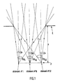
- FIG. 1 shows the shape of the real solid angles ⁇ I R of certain sensitive elements of a detector (for example elements n ° 1, 16 and 32), delimited by a cold screen E located at a distance z from the detector, this the latter being arranged in the focal plane F.
- ⁇ R1 , ⁇ R16 and ⁇ R32 be the solid angles corresponding respectively to these elements.
- the useful field ⁇ u of each of the elements has also been represented in this figure.
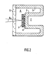
- the structure of the device of the invention shown in Figure 2 comprises a thin wafer of optical fibers 1 secured to a cold support 2 on which is fixed the detector 4 and arranged in contact or at very short distance from the latter.
- the cold support 2 is part of an envelope 3 closed at the front by a porthole 5.
- the wafer of fibers and the porthole are transparent in the desired spectral transmission band which can be chosen so as to adapt the spectral sensitivity of the assembly to the problem posed by the conditions of use.
- the fiber can play the role of a cold filter, which improves the sensitivity of the detector by reducing the bottom flux.
- the enclosed space 6 delimited by the casing 3 and the window 5 is empty of air or filled with a gas with low thermal conductivity.
- the part 2 of the envelope 3 serving as a support for the detector has the shape of a finger whose interior 7 is cooled by any method: intimate contact with a refrigerating medium such as liquid nitrogen, expansion of gas in the circuit open, use of a cold machine in closed circuit etc ...
- a refrigerating medium such as liquid nitrogen, expansion of gas in the circuit open, use of a cold machine in closed circuit etc ...
- the detector arranged in the closed space 6 is constituted by a mosaic of p rows of q elements. Thanks to the interposition of the optical fiber wafer between the incident beam and the detector, the rays received by each element are located within a solid angle ⁇ u corresponding to the acceptance angle of a fiber . These p rows of q elements provide pxq signal outputs constituting the detection function.
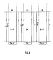
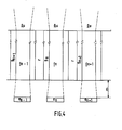
- FIGS. 3, 4 and 5 give possible applications for using cooled optical fibers defining the useful field of view ⁇ u of each detector element.
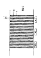
- the sketches are made for the characteristics of mosaics and optics mentioned above. We remind others. share that each fiber patch consists of the association of fibers (... f n-1 , f n , f n + 1 , ...) coated with a sheath (... g n-1 , g n , g n + 1 , ...) and linked by a resin-type coating r or welded together as shown in Figures 3 and 4, each fiber itself comprising a core glass and an outer glass being associated with a single detector element.
- the detector elements ... e n-1 , e " , e n + 1 ... are pressed opposite the corresponding fibers whereas in FIG. 4 they are separated by the distance d.
Landscapes
- Physics & Mathematics (AREA)
- General Physics & Mathematics (AREA)
- Spectroscopy & Molecular Physics (AREA)
- Radiation Pyrometers (AREA)
- Optical Couplings Of Light Guides (AREA)
- Light Receiving Elements (AREA)
Applications Claiming Priority (2)
| Application Number | Priority Date | Filing Date | Title |
|---|---|---|---|
| FR8505519A FR2580394B1 (fr) | 1985-04-12 | 1985-04-12 | Dispositif de limitation et d'uniformisation du champ de vue de mosaiques de detecteurs ir |
| FR8505519 | 1985-04-12 |
Publications (2)
| Publication Number | Publication Date |
|---|---|
| EP0198549A2 true EP0198549A2 (de) | 1986-10-22 |
| EP0198549A3 EP0198549A3 (de) | 1989-01-25 |
Family
ID=9318165
Family Applications (1)
| Application Number | Title | Priority Date | Filing Date |
|---|---|---|---|
| EP86200610A Withdrawn EP0198549A3 (de) | 1985-04-12 | 1986-04-10 | Vorrichtung zur Begrenzung und Vergleichmässigung des Sichtfeldes von Mosaikanordnungen von Infrarotdetektoren |
Country Status (3)
| Country | Link |
|---|---|
| EP (1) | EP0198549A3 (de) |
| JP (1) | JPS61239210A (de) |
| FR (1) | FR2580394B1 (de) |
Cited By (2)
| Publication number | Priority date | Publication date | Assignee | Title |
|---|---|---|---|---|
| DE3908627A1 (de) * | 1989-03-16 | 1990-09-20 | Bodenseewerk Geraetetech | Infrarotdetektor |
| EP3633323A4 (de) * | 2017-05-31 | 2021-03-03 | Hamamatsu Photonics K.K. | Lichtempfangsmodul für codierer und codierer |
Family Cites Families (9)
| Publication number | Priority date | Publication date | Assignee | Title |
|---|---|---|---|---|
| US3633031A (en) * | 1970-01-09 | 1972-01-04 | Continental Can Co | Can weld side-seam defect detector utilizing infrared detection means and collimator fiber optics |
| US3963926A (en) * | 1975-01-09 | 1976-06-15 | Texas Instruments Incorporated | Detector cold shield |
| JPS55121684A (en) * | 1979-03-13 | 1980-09-18 | Fujitsu Ltd | Light semiconductor device |
| US4323925A (en) * | 1980-07-07 | 1982-04-06 | Avco Everett Research Laboratory, Inc. | Method and apparatus for arraying image sensor modules |
| JPS57142526A (en) * | 1981-02-27 | 1982-09-03 | Fujitsu Ltd | Infrared detector |
| US4421985A (en) * | 1981-06-30 | 1983-12-20 | Vought Corporation | Dark field infrared telescope |
| JPS5843673A (ja) * | 1981-09-09 | 1983-03-14 | Fujitsu Ltd | 固体撮像装置 |
| JPS58167928A (ja) * | 1982-03-29 | 1983-10-04 | Mitsubishi Electric Corp | 赤外線検出器用コ−ルドシ−ルド構造体 |
| JPS608719A (ja) * | 1983-06-28 | 1985-01-17 | Fujitsu Ltd | 赤外線検知器 |
-
1985
- 1985-04-12 FR FR8505519A patent/FR2580394B1/fr not_active Expired
-
1986
- 1986-04-10 EP EP86200610A patent/EP0198549A3/de not_active Withdrawn
- 1986-04-11 JP JP61082406A patent/JPS61239210A/ja active Pending
Cited By (5)
| Publication number | Priority date | Publication date | Assignee | Title |
|---|---|---|---|---|
| DE3908627A1 (de) * | 1989-03-16 | 1990-09-20 | Bodenseewerk Geraetetech | Infrarotdetektor |
| US5015857A (en) * | 1989-03-16 | 1991-05-14 | Walter Bross | Infrared detector |
| EP0387556A3 (de) * | 1989-03-16 | 1991-06-05 | Bodenseewerk Gerätetechnik GmbH | Infrarotdetektor |
| EP3633323A4 (de) * | 2017-05-31 | 2021-03-03 | Hamamatsu Photonics K.K. | Lichtempfangsmodul für codierer und codierer |
| US11307060B2 (en) | 2017-05-31 | 2022-04-19 | Hamamatsu Photonics K.K. | Light-receiving module for encoder, and encoder |
Also Published As
| Publication number | Publication date |
|---|---|
| FR2580394B1 (fr) | 1987-10-09 |
| EP0198549A3 (de) | 1989-01-25 |
| FR2580394A1 (fr) | 1986-10-17 |
| JPS61239210A (ja) | 1986-10-24 |
Similar Documents
| Publication | Publication Date | Title |
|---|---|---|
| EP0124415A1 (de) | Optischer Sensor | |
| EP0015170B1 (de) | Spektrofotometrische Vorrichtung mit Fernmessung | |
| FR2581203A1 (fr) | Fibre de transmission d'image | |
| EP0559501A1 (de) | Unbeschichtetes Diamant-Laserfenster | |
| FR2748123A1 (fr) | Ensemble optique pour coupler un guide de lumiere et procede pour sa fabrication | |
| EP0216694B1 (de) | Vorrichtung zur Echtzeitkontrolle von Schweissungen, insbesondere für nicht direkt beobachtbare Schweissstellen | |
| FR2712706A1 (fr) | Sonde d'imagerie à infra-rouge portative. | |
| FR2718237A1 (fr) | Dispositif de mesure optique de température cryogénique. | |
| EP0419371B1 (de) | Vorrichtung zum Infrarotnachweis | |
| EP3973259B1 (de) | Infrarotlicht-ausstrahlende und -kontrollierende vorrichtung und gassensor mit einer solchen vorrichtung | |
| EP0018873B1 (de) | Kompakte optische Koppelungsvorrichtung und solch eine Vorrichtung enthaltender interferometrischer Gyrometer mit einer optischen Faser | |
| EP2715296A1 (de) | Spektroskopischer detektor und entsprechendes verfahren | |
| EP0198549A2 (de) | Vorrichtung zur Begrenzung und Vergleichmässigung des Sichtfeldes von Mosaikanordnungen von Infrarotdetektoren | |
| EP0069627B1 (de) | Vorrichtung zur evolutiven Ausleuchtung eines Objektes | |
| FR2634063A1 (fr) | Interface microsonde laser pour spectrometre de masse | |
| EP0463982B1 (de) | Vorrichtung zur kontinuierlichen Analyse und Impuls-Analyse der Energieverteilung eines Leistungslaserstrahls und Vorrichtung zum Ausrichten dieses Strahls | |
| EP0345121A1 (de) | Optisches Pyrometer mit mindestens einer optischen Faser | |
| EP2711686A1 (de) | Optischer Detektor eines Gases | |
| FR2687803A1 (fr) | Recepteur de rayonnement electromagnetique. | |
| FR2589254A1 (fr) | Appareil d'observation et de guidage, utilisable de jour et de nuit, pour systeme d'arme | |
| EP0528702B1 (de) | Abbildungssystem mit integrierter Abnutzungsmessung der in Transmission arbeitenden optischen Elemente und optronische Abbildungseinrichtung, bestehend aus solch einem Abbildungssystem | |
| EP0100124A1 (de) | Optisches Abbildungssystem für einen Zielsuchkopf | |
| EP0713119A1 (de) | Statisches weitwinkliges Infrarot-Überwachungsgerät mit Mehrfach-Detektorketten | |
| EP0061955B1 (de) | Vorrichtung und Verfahren zur Verbindung von Lichtleitfasern mit einer Kamera mit abgetastetem Schlitzverschluss | |
| EP0497649A1 (de) | Verfahren und Vorrichtung zur Ermittlung der Oberflächenbeschaffenheit eines lichtdurchlässigen optischen Elements |
Legal Events
| Date | Code | Title | Description |
|---|---|---|---|
| PUAI | Public reference made under article 153(3) epc to a published international application that has entered the european phase |
Free format text: ORIGINAL CODE: 0009012 |
|
| AK | Designated contracting states |
Kind code of ref document: A2 Designated state(s): BE DE FR GB IT NL SE |
|
| PUAL | Search report despatched |
Free format text: ORIGINAL CODE: 0009013 |
|
| AK | Designated contracting states |
Kind code of ref document: A3 Designated state(s): BE DE FR GB IT NL SE |
|
| STAA | Information on the status of an ep patent application or granted ep patent |
Free format text: STATUS: THE APPLICATION IS DEEMED TO BE WITHDRAWN |
|
| 18D | Application deemed to be withdrawn |
Effective date: 19890922 |
|
| RIN1 | Information on inventor provided before grant (corrected) |
Inventor name: FOUILLOY, JEAN-PIERRE Inventor name: MARCHE, PIERRE |