EP0198313A2 - Système de suspension avec essieu à construction flexible - Google Patents
Système de suspension avec essieu à construction flexible Download PDFInfo
- Publication number
- EP0198313A2 EP0198313A2 EP86104426A EP86104426A EP0198313A2 EP 0198313 A2 EP0198313 A2 EP 0198313A2 EP 86104426 A EP86104426 A EP 86104426A EP 86104426 A EP86104426 A EP 86104426A EP 0198313 A2 EP0198313 A2 EP 0198313A2
- Authority
- EP
- European Patent Office
- Prior art keywords
- spring steel
- suspension system
- flexible axle
- frame type
- type flexible
- Prior art date
- Legal status (The legal status is an assumption and is not a legal conclusion. Google has not performed a legal analysis and makes no representation as to the accuracy of the status listed.)
- Granted
Links
Images


Classifications
-
- B—PERFORMING OPERATIONS; TRANSPORTING
- B60—VEHICLES IN GENERAL
- B60G—VEHICLE SUSPENSION ARRANGEMENTS
- B60G3/00—Resilient suspensions for a single wheel
- B60G3/18—Resilient suspensions for a single wheel with two or more pivoted arms, e.g. parallelogram
- B60G3/28—Resilient suspensions for a single wheel with two or more pivoted arms, e.g. parallelogram at least one of the arms itself being resilient, e.g. leaf spring
-
- B—PERFORMING OPERATIONS; TRANSPORTING
- B60—VEHICLES IN GENERAL
- B60G—VEHICLE SUSPENSION ARRANGEMENTS
- B60G11/00—Resilient suspensions characterised by arrangement, location or kind of springs
-
- B—PERFORMING OPERATIONS; TRANSPORTING
- B60—VEHICLES IN GENERAL
- B60G—VEHICLE SUSPENSION ARRANGEMENTS
- B60G21/00—Interconnection systems for two or more resiliently-suspended wheels, e.g. for stabilising a vehicle body with respect to acceleration, deceleration or centrifugal forces
- B60G21/02—Interconnection systems for two or more resiliently-suspended wheels, e.g. for stabilising a vehicle body with respect to acceleration, deceleration or centrifugal forces permanently interconnected
- B60G21/04—Interconnection systems for two or more resiliently-suspended wheels, e.g. for stabilising a vehicle body with respect to acceleration, deceleration or centrifugal forces permanently interconnected mechanically
- B60G21/05—Interconnection systems for two or more resiliently-suspended wheels, e.g. for stabilising a vehicle body with respect to acceleration, deceleration or centrifugal forces permanently interconnected mechanically between wheels on the same axle but on different sides of the vehicle, i.e. the left and right wheel suspensions being interconnected
-
- B—PERFORMING OPERATIONS; TRANSPORTING
- B60—VEHICLES IN GENERAL
- B60G—VEHICLE SUSPENSION ARRANGEMENTS
- B60G7/00—Pivoted suspension arms; Accessories thereof
- B60G7/02—Attaching arms to sprung part of vehicle
Definitions
- the present invention relates to a frame type flexible axle suspension system used as an independent suspension system in a drive system of a motor vehicle, or an automobile in particular.
- suspension system is one of important subassemblies of a modern automobile. It consists of elastic elements, buffer, guiding mechanism and stabilizing rod. Suspension system greatly affects smoothness and stability of drive of an automobile, and also has influence on many performance features of an automobile, such as roadability, fuel economy etc. Therefore, improvements and patent applications on suspension system have been proposed and submitted again and again.
- guiding mechanism it can be classified into two groups: dependent and independent suspension system. Independent suspension system can be further calssified into a number of types. Up to now following types have been developed: dual cross arm type, single cross arm type, longitudinal arm type, single oblique arm type and sliding column with swinging arm type.
- the objective of present invention is to propose a totally new and unique independent suspension system, that is, a frame type flexible axle suspension system. It integrates guiding, stabilizing, buffering functions and hinges of a suspension system into a simplified frame construction. This suspension's coming out solves above mentioned problems which exist in presently used suspension systems.
- the frame type flexible axle suspension system of present invention includes two parallel shafts made of spring steel. Ends of these shafts pass through a pair of link stands which are perpendicular to spring steel shafts, thus form a frame construction.
- Link stands are connected with elevation shaft or driving shaft or wheel shaft.
- elastic sleeves are fixed on spring steel shafts by hoops.
- supporting stands are connected with hoops and fixed on chassis of automobile.
- the elastic sleeves can stand both the normal pressure in the tangent direction and the shearing force in the traverse direction, thus ensure a secure connection of suspension system with vehicle body.
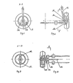
- Guiding function (see Fig. 4 and Fig. 5)
- wheel When a wheel accepts a vertical force from the ground (in direction F), due to the fact that the spring steel shaft has elasticity, wheel will swivel around the center A (or B) in direction N within a radius L (or I), thus guiding function is performed.
- Proper adjustment of the distance between A and B may change the distance from wheel to A (orB), thus may adjust the radius within which the wheel can swivel in direction N to achieve the objective of adjusting guiding radius.
- Link stands are rigidly connected with spring steel shafts through conic holes and nuts.
- Buffering function When a wheel accepts a ground impact, it transfers the impact to elastic metal frame which is fixed on supporting components connected with vehicle body through rubber elastic sleeves. Since elastic deformation of spring steel shaft absorbs impact energy, the spring steel shaft as an elastic element performs the buffering function.
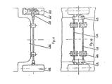
- Stabilizing function In order to improve smoothness of drive of an automobile, the rigidity of elastic elments in a suspension system should be properly reduced. However, when an automobile makes a turn, centrifugal force causes the automobile too large a slant that reduces its stability. Therefore, automobiles (mostly cars) with indepen- Tr suspension system are to have an additional spring steel shaft which, passing through vehicle body, is fixed on wheel shaft on both sides, thus in a certain degree enhances rigidity of outer suspension system during a turn, decreases the slant of vehicle body and improves stability.
- the frame type flexible axle suspension system of present invention does not need additional stabilizing shaft device, because when an automobile makes a turn, the outer spring steel shaft deforms, thus affects bending deformation of whole spring steel shaft, causes a spontaneous deformation of inner spring steel shaft. Therefore, outer and inner sides are lowering almost simultaneously during a turn, slant angle decreases one half at the least, thus stability is ensured.
- This unique suspension system is of a simple frame construction. It combines guiding, buffering, stabilizing functions of present complex suspension system into a simplified system. Moreover, it has following effects: manufacturing process of suspension elements is simplified, the amount of parts, especially connecting elements such as hinges, is decreased, assembly and maintenence becomes easier, break down rate is lowered.
- This independent suspension system makes it possible to use basically common construction for front and rear axle suspension. Therefore, it further simplifies manufacturing process, reduces the amount of assembly work, at the same time favours repair and maintenence work.
- this suspension system can be considered as a flexible suspension system which can be adjusted flexibly and conveniently to satisfy requirements of vehicles of various different types.
- spring steel shafts (12, 14) In a flexible axle suspension system the material of spring steel shafts (12, 14) is very important. Spring steel with good mechanical characteristics and high elasticity strength, such as manganese steel and silicon manganese steel, are to be selected. In particular, spring steel 65Mn and 60 (Si 2 Mn) are more commonly used materials.
- Shape, section size and length of spring steel shafts (12, 14) are to be selected based on differences in type, construction and loading capacity of automobile. In one and the same frame construction (10), two spring steel shafts (12, 14) must meet the requirement of parallelism. however, shapes, section sizes and lengths may be identical or not identical. Depending on concrete design specification, it can be adjusted in a certain range. Section of steel shaft may have various forms, such as round, oval, square, rectangle etc. If spring steel shafts (12, 14) have round sections, then for a mini- automobile their diameter should not be less than 8 mm., For a ordinary car or a passenger-cargo dual purpose truck their diameter should be more than 20 mm.
- Two ends of spring steel shafts (12, 14) are to pass through individually two conic holes of a pair of link stands (16 and 18) which are perpendicular to the steel shafts to form a frame construction - (10) (see Fig. 1).
- the steel shafts should be firmly connected with the link stands. There should not be any traverse displacement between them.
- at the end of spring steel shaft there may be a fine thread folowed by a conic thransition part, the conicity of which should match with the conicity of holes (48, 50) on the link stands. Then the steel shaft is fixed on link stands by nuts.
- the distance h (see Fig. 4) between two parallel spring steel shafts in the frame construction - (10), i.e. the distance h (see Fig. 14, 15, 16) between centers of two holes on link stands, through which steel shafts are to pass, should be selected according to vehicle body structure.
- the distance between two parallel steel shafts should not be less than one fifth of wheel diameter D, that is , h % 1/5D.
- Link stands (16, 18) play an important role in flexible axle suspension system of automobile. It not only connects spring steel shafts to form a frame construction (10), but also connects suspension system with drive shaft (32 or 44) or elevation shaft (30) or wheel shaft (62), thus comprises an important part of chassis of automobile.
- Link stands (16, 18) are perpendicular to spring steel shafts and disposed at both ends of this pair of steel shafts. They are integrated with steel shafts by fasteners, thus a rigid frame construction (10) is formed.
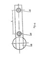
- Link stands are essentially plate stands - (see Fig. 12, 13). Mainly, on link stands there are two conic holes (48, 50) for spring steel shafts to pass through and a connecting part 57 for drive shaft (32 or 44) or elevation shaft (30) or wheel shaft (62) to be connected. Conic holes match with conic parts of spring steel shaft ends. At ends of steel shafts there are sections with fine thread, right next to above mentioned conic parts of steel shafts. Thus, it is possible to integrate steel shafts with link stands by fasteners such as nuts.
- Shape and size of link stands may be adjusted according to requirements. By making appropriate changes in shape and size of link stands according to concrete difference between front and rear axle constructions it is possible to apply the suspension system simultaneously to front and rear axles.
- Positions of two conic holes (48, 50) on fink stands are to be selected according to characteristics of automobiles of different types. As shown in Fig. 14, two holes are located above the connecting part of link stands. It is suitable for use in automobiles with good roadibility. In Fig. 15 two connection lines of each center of hole with center of respecitive connecting part of link stand are almost perpendicular. It is suitable for use in automobile construction where its disposition hinders engine or fuel tank. In Fig. 16 two holes are arranged at one and the same side of connecting part of link stand. It is suitable for use in automobile with special construction. It is also possible to use various constructions of link stands to arrange relative positions of two holes to avoid wheel interference. However, no matter how to arrange the disposition, two conditions are to be met 1.
- Positions of conic holes in each pair of link stands should ensure that two spring steel shafts are paralle. 2. Angle between the plane formed by two parallel steel shafts and the water level of chassis should not be larger than 60°, that is, should not be in a range nearly vertical to the ground.
- Connecting part of link stand (56) is to be designed and selected according to concrete construction and application case.
- its drive shaft (32) may be located below frame structue (10) (as shown in Fig. 2), may also be located above frame structure (10) (as shown in Fig. 4 and Fig. 6), wherein connecting part of link stand (56) has to have holes to connect elevation shaft (30) or drive shaft (32).
- Fig. 12 and Fig. 13 are simple schema of link stand of front axle where hole (64) is connected with elevation shaft (30).
- the connecting part of link stand has a hole for drive shaft (44) to pass through.
- rear axle passive suspension system (as shown in Fig. 10 and 11) the connecting part of link stand is a blind hole.
- Each supporting component consists of a supporting stand, a hoop, an elastic sleeve.
- Elastic sleeves (20, 21, 22, 23) have shock absorbing feature, at the same time functions as a hinge for guiding action. They are made of rubber or synthetic rubber product, e.g. rubber (BR), polyurethane (UR), and thermoplastic elastic material - (SBS) etc. Elastic sleeves are directly put on appropriate location of spring steel shafts (12, 14), stuck together by adhesives, or solidified on spring steel shaft by rubber vulcanizing process. Sleeves may have various forms, such as cylindrical form or form of bearing housing.
- supporting stand (26) and spring steel shafts (12, 14) may be integrated by filling rubber between them, a method normally called “vulcanization', to ensure that it is elastic and strong.
- Hoops (24) are used to band elastic sleeves firmly on spring steel shafts. Hoops may have various constructions. Ordinary clamping mechanism is capable to achieve this objective.
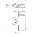
- Fig. 17, 18 and 19 show one of those ordinary hoop mechanisms, where hoop (24) consists of two halves of steel parts, the form of inner clamping surface suits the form of elastic sleeves (20, 21, 22, 23), the outer form suits supporting stand (26). On both halves of the hoop there are holes with threades (58). Two halves of the hoop are clamped together by bolts (52), thus elastic sleeves are tightly pressed on spring steel shafts (12, 14). By controlling tightening force of bolts it is possible to adjust the pressure of elastic sleeves on steel shafts.
- Supporting stand (26) is fixed on hoop (24). It can be made integral with hoop, or fixed on hoop by means of mechanical fastening method or welding process. Supporting stand has four holes. By means of bolts or rivets it can be securely fastened to chassis (40). Finally it serves as a support for chassis.
- Supporting stand may have a round, triangular, rectangular or square form according to construction of chassis, but normally rectangular form is prefered.
- distance between each pair of supporting components can be adjusted.
- the benefit is that guiding feature and stability of suspension can be adjusted. Since supporting components make suspension possess guiding feature, at the same time make steel shafts function like stabilizing rod, increase in the distance will improve the stability of suspension, decrease in the distance will improve guiding feature, but decrease stability. Therefore, by adjusting this distance it is possible to find an ideal combination of guiding and stabilizing features.
- by adjusting the distance it is possible to adjust natural frequency of virbration of the elastic element--spring steel shaft, thus to improve smoothness of automobile.
- the distance between supporting stands of two spring steel shafts may be different. The amount of difference may also be adjusted.
- the advantage is that in a certain degree it makes rigidity of suspension variable depending on vehicle's loading. In this way the natural frequency of vehicle body changes very little. Smoothness of drive of vehicle is improved which is most important for buses and cars.
- each steel shaft should be disposed at 1/6 H to 2/6 H and at 4/6 H to 5/6 H respectively. (H: distance between two wheels, see Fig. 4).
- each steel shaft should be symmetric to center line of distance between two wheels.
- spring steel shaft (12) there are two elastic sleeves (20) and - (21). If (20) is placed at 1/6 H (H: distance between two wheels), then (21) should be placed at 5/6H. Elastic sleeves (20) and (21) are symmetric to center line of distance between two wheels.
- elastic sleeves (20 and 21) and (22 and 23) on two respective spring steel shafts (12) and (14) of the same frame construction are not necessarily to be placed at the same distance, see Fig. 4.
- elastic sleeves (20) and (21) on spring steel shaft (12) are placed at 2/6 H and 4/6H (H: distance between two wheels) respectively, but elastic sleeves (22) and (23) on spring steel shaft (14) are placed at 1/6 H and 5/6H respectively.
- elastic sleeves (20) and - (21) or (22) and (23) may be placed at the same distance between two wheels.
- frame type flexible axle suspension system is basically characterized as two parallel spring steel shafts (12, 14), ends of which pass through a pair of link stands (16, 18) respectively, which are perpendicular to spring steel shafts. Combined together, they form a frame construction (10).
- Link stands are connected with elevation shaft or drive shaft or wheel shaft.
- Elastic sleeves (20, 21, 22, 23) are fastened on spring steel shafts (12 or 14) respectively by means of hoops.
- Supporting stand (26) is connected with hoops and fixed on chassis or main beam (40) of automobile.
- Spring steel 60si2Mn was selected for spring steel shafts of both front and rear axles. Diameter of all steel shafts is 20mm. The distance between two steel shafts of front axle is approximately one third of wheel diameter. The distance between two spring steel shafts of rear axle is 250 mm.
- Elastic sleeves are made of rubber (BR). They have cylindrical form with inner diameter of 18 mm, thickness of 20 mm and length of 40 mm. Sleeves are firmly stuck to steel shafts with 502 adhesive. Hoops are used to fasten elastic sleeves on to - steel shafts as shown in Fig. 17, 19. Hoops are welded on supporting stands and fixed on main frame of automobile by bolts which pass through four thread holes on supporting stands. Elastic sleeves of front and rear axles are placed at 2/9H and 7!9H (H: distance between two wheels) respectively.
- Using frame type flexible axle suspension system greatly simplifies the whole suspension mechanism, reduces the amount of parts and components, thus makes manufacturing easier and assembly simpler, reduces cost, facilitates mainten- sence and repair, decreases vehicle body's weight, saves energy consumption accordingly and reduces the noise level caused by friction between parts.
Landscapes
- Engineering & Computer Science (AREA)
- Mechanical Engineering (AREA)
- Vehicle Body Suspensions (AREA)
Applications Claiming Priority (2)
| Application Number | Priority Date | Filing Date | Title |
|---|---|---|---|
| CN85101438A CN85101438B (zh) | 1985-04-01 | 1985-04-01 | 框架式弹性桥机构 |
| CN85101438 | 1985-04-01 |
Publications (3)
| Publication Number | Publication Date |
|---|---|
| EP0198313A2 true EP0198313A2 (fr) | 1986-10-22 |
| EP0198313A3 EP0198313A3 (en) | 1986-12-17 |
| EP0198313B1 EP0198313B1 (fr) | 1990-03-21 |
Family
ID=4791845
Family Applications (1)
| Application Number | Title | Priority Date | Filing Date |
|---|---|---|---|
| EP86104426A Expired EP0198313B1 (fr) | 1985-04-01 | 1986-04-01 | Système de suspension avec essieu à construction flexible |
Country Status (5)
| Country | Link |
|---|---|
| US (1) | US4772042A (fr) |
| EP (1) | EP0198313B1 (fr) |
| JP (1) | JPH0643161B2 (fr) |
| CN (1) | CN85101438B (fr) |
| DE (1) | DE3543085A1 (fr) |
Families Citing this family (12)
| Publication number | Priority date | Publication date | Assignee | Title |
|---|---|---|---|---|
| JPS6341212A (ja) * | 1986-08-07 | 1988-02-22 | Mazda Motor Corp | 自動車のサスペンシヨン装置 |
| US5184842A (en) * | 1991-08-22 | 1993-02-09 | Stockton Jeffrey M | Vehicle suspension mechanism |
| US5409254A (en) * | 1992-05-11 | 1995-04-25 | A. O. Smith Corporation | Rear suspension with aligned coil springs and twist beam axle |
| KR950003412U (ko) * | 1993-07-21 | 1995-02-16 | 최윤식 | 자동차의 완충장치 |
| US5844397A (en) * | 1994-04-29 | 1998-12-01 | Reda Pump | Downhole pumping system with variable speed pulse width modulated inverter coupled to electrical motor via non-gap transformer |
| US6619527B1 (en) | 2000-10-10 | 2003-09-16 | Illinois Tool Works Inc. | Combustion powered tool suspension for iron core fan motor |
| US7040520B2 (en) * | 2002-09-12 | 2006-05-09 | Illinois Tool Works Inc. | Fan motor suspension mount for a combustion-powered tool |
| CH702282A1 (de) * | 2009-11-27 | 2011-05-31 | Alstom Technology Ltd | Fahrzeug zur selbständigen Inspektion von schwer zugänglichen Innenräumen. |
| CN104512211A (zh) * | 2013-09-27 | 2015-04-15 | 王玉 | 一种平衡轴 |
| CN104385868B (zh) * | 2014-11-19 | 2016-03-09 | 冯胜 | 汽车独立悬挂系统 |
| CN106696621B (zh) * | 2017-01-23 | 2023-07-04 | 浙江吉利新能源商用车有限公司 | 一种麦弗逊独立悬架总成 |
| IT201900005556A1 (it) * | 2019-04-10 | 2020-10-10 | Piaggio & C Spa | Motoveicolo rollante con dispositivo di blocco del rollio |
Citations (8)
| Publication number | Priority date | Publication date | Assignee | Title |
|---|---|---|---|---|
| US2553746A (en) * | 1947-06-12 | 1951-05-22 | Euclid Road Machinery Co | Front axle suspension assembly |
| FR1293498A (fr) * | 1960-07-07 | 1962-05-11 | Fiat Spa | Suspension à roues indépendantes pour véhicules automobiles |
| FR1559705A (fr) * | 1966-12-15 | 1969-03-14 | ||
| FR2005243A1 (fr) * | 1968-04-01 | 1969-12-12 | Kolbe Joachim | |
| US3975083A (en) * | 1974-07-24 | 1976-08-17 | Reflexite Corporation | Wide angle retroreflector assembly and method of making same |
| US3992036A (en) * | 1975-07-07 | 1976-11-16 | Ford Motor Company | Independent front suspension system for a motor vehicle |
| DE3131036A1 (de) * | 1981-08-05 | 1983-02-24 | WOCO Franz-Josef Wolf & Co, 6483 Bad Soden-Salmünster | Gummimetallager |
| DE3302627A1 (de) * | 1982-02-22 | 1983-09-01 | Volkswagenwerk Ag, 3180 Wolfsburg | Einzelradaufhaengung fuer die raeder einer kraftfahrzeug-hinterachse |
Family Cites Families (12)
| Publication number | Priority date | Publication date | Assignee | Title |
|---|---|---|---|---|
| GB355714A (en) * | 1930-05-27 | 1931-08-27 | Spencer Bernau Wilks | Driving axles for motor vehicles |
| US2075531A (en) * | 1933-08-07 | 1937-03-30 | Lundelius & Eccleston Motors C | Vehicle chassis-front end construction |
| US2025669A (en) * | 1933-08-07 | 1935-12-24 | Lundelius & Eccleston Motors C | Differential and spring mounting |
| US2757017A (en) * | 1953-06-18 | 1956-07-31 | Ford Motor Co | Independent wheel suspension for motor vehicles |
| US2824734A (en) | 1955-04-22 | 1958-02-25 | Frank F Linn | Vehicle axle and suspension therefor |
| DE1190810B (de) * | 1961-08-09 | 1965-04-08 | Daimler Benz Ag | Blattfederung, insbesondere fuer Kraftfahrzeuge |
| JPS5110524Y2 (fr) * | 1972-07-25 | 1976-03-22 | ||
| GB2010759A (en) * | 1977-12-23 | 1979-07-04 | Ford Motor Co | Torsion bar for a vehicle suspensions |
| US4313618A (en) * | 1980-01-28 | 1982-02-02 | Robinson Russell S | Resilient suspension means for light vehicles |
| FR2516455B1 (fr) * | 1981-11-18 | 1986-12-12 | Bertin & Cie | Suspension de vehicule automobile par lame elastique |
| US4458918A (en) | 1981-12-24 | 1984-07-10 | Ford Motor Company | Rear wheel suspension with a transverse leaf spring |
| JPS59156807U (ja) * | 1983-04-06 | 1984-10-22 | 日産自動車株式会社 | インデペンデント・サスペンシヨン装置 |
-
1985
- 1985-04-01 CN CN85101438A patent/CN85101438B/zh not_active Expired
- 1985-12-05 DE DE19853543085 patent/DE3543085A1/de active Granted
- 1985-12-09 JP JP60275230A patent/JPH0643161B2/ja not_active Expired - Lifetime
-
1986
- 1986-03-04 US US06/835,889 patent/US4772042A/en not_active Expired - Lifetime
- 1986-04-01 EP EP86104426A patent/EP0198313B1/fr not_active Expired
Patent Citations (8)
| Publication number | Priority date | Publication date | Assignee | Title |
|---|---|---|---|---|
| US2553746A (en) * | 1947-06-12 | 1951-05-22 | Euclid Road Machinery Co | Front axle suspension assembly |
| FR1293498A (fr) * | 1960-07-07 | 1962-05-11 | Fiat Spa | Suspension à roues indépendantes pour véhicules automobiles |
| FR1559705A (fr) * | 1966-12-15 | 1969-03-14 | ||
| FR2005243A1 (fr) * | 1968-04-01 | 1969-12-12 | Kolbe Joachim | |
| US3975083A (en) * | 1974-07-24 | 1976-08-17 | Reflexite Corporation | Wide angle retroreflector assembly and method of making same |
| US3992036A (en) * | 1975-07-07 | 1976-11-16 | Ford Motor Company | Independent front suspension system for a motor vehicle |
| DE3131036A1 (de) * | 1981-08-05 | 1983-02-24 | WOCO Franz-Josef Wolf & Co, 6483 Bad Soden-Salmünster | Gummimetallager |
| DE3302627A1 (de) * | 1982-02-22 | 1983-09-01 | Volkswagenwerk Ag, 3180 Wolfsburg | Einzelradaufhaengung fuer die raeder einer kraftfahrzeug-hinterachse |
Non-Patent Citations (1)
| Title |
|---|
| STAHLSCHL]SSEL, 1983, page 42, Verlag Stahlschl}ssel Wegst GmbH, Marbach, DE; * |
Also Published As
| Publication number | Publication date |
|---|---|
| JPH0643161B2 (ja) | 1994-06-08 |
| DE3543085C2 (fr) | 1992-04-09 |
| CN85101438A (zh) | 1986-08-20 |
| EP0198313A3 (en) | 1986-12-17 |
| CN85101438B (zh) | 1986-12-10 |
| US4772042A (en) | 1988-09-20 |
| JPS61229606A (ja) | 1986-10-13 |
| DE3543085A1 (de) | 1986-10-09 |
| EP0198313B1 (fr) | 1990-03-21 |
Similar Documents
| Publication | Publication Date | Title |
|---|---|---|
| US5996981A (en) | Reduced size bushing for beam-type axle suspension system | |
| US6357769B1 (en) | Independent rear suspension system | |
| US4779893A (en) | Strut type vehicle wheel suspension | |
| US7392997B2 (en) | Front suspension strut | |
| EP1171322B1 (fr) | Systeme de suspension pour roue de vehicule | |
| US4589677A (en) | Suspension for a rigid axle for vehicles | |
| US20050242541A1 (en) | Rigid axle for a vehicle, comprising integrated trailing arms and mounting brackets | |
| JPH01502420A (ja) | 車輌用懸架装置 | |
| EP0198313A2 (fr) | Système de suspension avec essieu à construction flexible | |
| US6042131A (en) | Vehicle rear suspension system | |
| US3952824A (en) | Rigid rear axle for motor vehicles | |
| US20070267259A1 (en) | Rear suspension eyelet mount shock assembly | |
| US5816606A (en) | Horizontally-mounted rear shock absorber for lightweight motor vehicle | |
| GB2410726A (en) | Integral spring-axle apparatus | |
| CN109070671A (zh) | 具有由纤维复合材料制成的车轮导向板簧元件的车辆独立悬架 | |
| CN100453379C (zh) | 车架梁扭矩衰减器 | |
| CA1192919A (fr) | Suspension pour roues de vehicule | |
| US4580809A (en) | Vehicle suspension system | |
| US3897844A (en) | Suspension modifying means for leaf spring suspensions | |
| US4451054A (en) | Vehicle suspension system | |
| US4813695A (en) | Multi-axle vehicle suspension | |
| WO1991004875A1 (fr) | Suspension pour roue arriere | |
| US5255936A (en) | Rear suspension assembly | |
| US20070267836A1 (en) | Non-symmetrical tapered mono-leaf spring | |
| EP0850148A2 (fr) | Ressort de suspension a torsion de caoutchouc pour vehicule lege a moteur |
Legal Events
| Date | Code | Title | Description |
|---|---|---|---|
| PUAI | Public reference made under article 153(3) epc to a published international application that has entered the european phase |
Free format text: ORIGINAL CODE: 0009012 |
|
| AK | Designated contracting states |
Kind code of ref document: A2 Designated state(s): FR GB IT |
|
| PUAL | Search report despatched |
Free format text: ORIGINAL CODE: 0009013 |
|
| AK | Designated contracting states |
Kind code of ref document: A3 Designated state(s): FR GB IT |
|
| 17P | Request for examination filed |
Effective date: 19870423 |
|
| 17Q | First examination report despatched |
Effective date: 19880411 |
|
| GRAA | (expected) grant |
Free format text: ORIGINAL CODE: 0009210 |
|
| AK | Designated contracting states |
Kind code of ref document: B1 Designated state(s): FR GB IT |
|
| ITF | It: translation for a ep patent filed |
Owner name: BARZANO' E ZANARDO MILANO S.P.A. |
|
| ET | Fr: translation filed | ||
| PLBE | No opposition filed within time limit |
Free format text: ORIGINAL CODE: 0009261 |
|
| STAA | Information on the status of an ep patent application or granted ep patent |
Free format text: STATUS: NO OPPOSITION FILED WITHIN TIME LIMIT |
|
| 26N | No opposition filed | ||
| ITTA | It: last paid annual fee | ||
| PGFP | Annual fee paid to national office [announced via postgrant information from national office to epo] |
Ref country code: GB Payment date: 19990323 Year of fee payment: 14 |
|
| PGFP | Annual fee paid to national office [announced via postgrant information from national office to epo] |
Ref country code: FR Payment date: 19990326 Year of fee payment: 14 |
|
| PG25 | Lapsed in a contracting state [announced via postgrant information from national office to epo] |
Ref country code: GB Free format text: LAPSE BECAUSE OF NON-PAYMENT OF DUE FEES Effective date: 20000401 |
|
| GBPC | Gb: european patent ceased through non-payment of renewal fee |
Effective date: 20000401 |
|
| PG25 | Lapsed in a contracting state [announced via postgrant information from national office to epo] |
Ref country code: FR Free format text: LAPSE BECAUSE OF NON-PAYMENT OF DUE FEES Effective date: 20001229 |
|
| REG | Reference to a national code |
Ref country code: FR Ref legal event code: ST |
|
| PG25 | Lapsed in a contracting state [announced via postgrant information from national office to epo] |
Ref country code: IT Free format text: LAPSE BECAUSE OF NON-PAYMENT OF DUE FEES;WARNING: LAPSES OF ITALIAN PATENTS WITH EFFECTIVE DATE BEFORE 2007 MAY HAVE OCCURRED AT ANY TIME BEFORE 2007. THE CORRECT EFFECTIVE DATE MAY BE DIFFERENT FROM THE ONE RECORDED. Effective date: 20050401 |