EP0197919B1 - Förderband, insbesondere für getreideartige materialien - Google Patents
Förderband, insbesondere für getreideartige materialien Download PDFInfo
- Publication number
- EP0197919B1 EP0197919B1 EP84901826A EP84901826A EP0197919B1 EP 0197919 B1 EP0197919 B1 EP 0197919B1 EP 84901826 A EP84901826 A EP 84901826A EP 84901826 A EP84901826 A EP 84901826A EP 0197919 B1 EP0197919 B1 EP 0197919B1
- Authority
- EP
- European Patent Office
- Prior art keywords
- belt
- conveyor
- housing
- dog
- profiles
- Prior art date
- Legal status (The legal status is an assumption and is not a legal conclusion. Google has not performed a legal analysis and makes no representation as to the accuracy of the status listed.)
- Expired
Links
- 239000000463 material Substances 0.000 title claims abstract description 44
- 239000002699 waste material Substances 0.000 claims description 3
- 208000003643 Callosities Diseases 0.000 abstract description 3
- 206010020649 Hyperkeratosis Diseases 0.000 abstract description 3
- 235000005824 Zea mays ssp. parviglumis Nutrition 0.000 abstract description 3
- 235000002017 Zea mays subsp mays Nutrition 0.000 abstract description 3
- 235000005822 corn Nutrition 0.000 abstract description 3
- 240000008042 Zea mays Species 0.000 abstract 1
- 241000282472 Canis lupus familiaris Species 0.000 description 18
- 229910000831 Steel Inorganic materials 0.000 description 5
- 239000010959 steel Substances 0.000 description 5
- 239000005060 rubber Substances 0.000 description 3
- 239000002023 wood Substances 0.000 description 3
- 241000209149 Zea Species 0.000 description 2
- 238000000034 method Methods 0.000 description 2
- 229920002994 synthetic fiber Polymers 0.000 description 2
- 238000004140 cleaning Methods 0.000 description 1
- 238000010276 construction Methods 0.000 description 1
Images


Classifications
-
- B—PERFORMING OPERATIONS; TRANSPORTING
- B65—CONVEYING; PACKING; STORING; HANDLING THIN OR FILAMENTARY MATERIAL
- B65G—TRANSPORT OR STORAGE DEVICES, e.g. CONVEYORS FOR LOADING OR TIPPING, SHOP CONVEYOR SYSTEMS OR PNEUMATIC TUBE CONVEYORS
- B65G19/00—Conveyors comprising an impeller or a series of impellers carried by an endless traction element and arranged to move articles or materials over a supporting surface or underlying material, e.g. endless scraper conveyors
- B65G19/14—Conveyors comprising an impeller or a series of impellers carried by an endless traction element and arranged to move articles or materials over a supporting surface or underlying material, e.g. endless scraper conveyors for moving bulk material in closed conduits, e.g. tubes
- B65G19/16—Conveyors comprising an impeller or a series of impellers carried by an endless traction element and arranged to move articles or materials over a supporting surface or underlying material, e.g. endless scraper conveyors for moving bulk material in closed conduits, e.g. tubes the impellers being elements having an area substantially smaller than that of the conduit cross-section
-
- B—PERFORMING OPERATIONS; TRANSPORTING
- B65—CONVEYING; PACKING; STORING; HANDLING THIN OR FILAMENTARY MATERIAL
- B65G—TRANSPORT OR STORAGE DEVICES, e.g. CONVEYORS FOR LOADING OR TIPPING, SHOP CONVEYOR SYSTEMS OR PNEUMATIC TUBE CONVEYORS
- B65G15/00—Conveyors having endless load-conveying surfaces, i.e. belts and like continuous members, to which tractive effort is transmitted by means other than endless driving elements of similar configuration
- B65G15/04—Conveyors having endless load-conveying surfaces, i.e. belts and like continuous members, to which tractive effort is transmitted by means other than endless driving elements of similar configuration the load being carried on the lower run of the endless surface
-
- B—PERFORMING OPERATIONS; TRANSPORTING
- B65—CONVEYING; PACKING; STORING; HANDLING THIN OR FILAMENTARY MATERIAL
- B65G—TRANSPORT OR STORAGE DEVICES, e.g. CONVEYORS FOR LOADING OR TIPPING, SHOP CONVEYOR SYSTEMS OR PNEUMATIC TUBE CONVEYORS
- B65G2201/00—Indexing codes relating to handling devices, e.g. conveyors, characterised by the type of product or load being conveyed or handled
- B65G2201/04—Bulk
Definitions
- the present invention relates to a conveyor having for its effective operation divided material flows, consisting of a housing; an inlet to the housing for the material to be conveyed; a driven endless belt arranged within said housing; dog profiles fixed transversely on the outside of the belt spaced apart from each other; and at least one outlet from the conveyor for said material (see for example US-A-3219173).
- a comparatively high speed at least 3 times higher speed than a chain conveyor
- a housing or trough 30 is at opposite ends provided with shafts 31, 32, on which pulley wheels 33, 34 are mounted. One of the pulleys is driven and the other runs freely.
- a belt 35 having a width adapted in relation to the housing, has transverse dog profiles 36 fixed to its outer surface. The dog profiles form interspaces 37 between the belt and the bottom of the housing 38.
- An inlet 39 feeds the material over a distributor 40 (see Fig. 8) past the upper belt run, so that the material is collected on the bottom of the housing as well as up onto the upper surface of the lower belt run.
- a distributor 42 arranged at chosen position and preferably just ahead of outlet 45 feeds the material 43 away from the belt and downwardly through gaps 44 between the belt and the side walls of the housing, so that a common material flow is formed which is conveyed along the bottom of the housing towards the outlet 45.
- the upper run of the belt is supported by a support plate 46 fastened to the side walls of the housing, or rolls 46b, the shafts of which are journalled in the side walls of the housing.
- the shaft 31 is mounted in bearings which are adjustable in the longitudinal direction of the housing.
- the shaft 32 is mounted in bearings and can be driveable by means of a motor with reduction gear.
- the dog profiles have, as best shown in Fig. 3, inclined surfaces 47.
- Semi-circular shaped deflector 48 guides the waste material 49 at the drive end and this material is brought back to the opposite end of the housing, where a semi-circular deflector 50 can be arranged.
- a brush or scrape device 51 can be positioned immediately ahead of the drive pulley 34 in order to clean the belt.
- the belt with its low weight and the dogs made of material having low friction qualities affords a conveyor with very low demands.
- Figs 3 and 4 show in larger scale a belt 35 provided with dog profiles 36.
- the belt can be made of rubber or any other appropriate material, homogeneous or perforated with small holes or close-meshed.
- An appropriate belt may consist of rubber belt reinforced with synthetic material or steel-wires having inconsiderable elongation upon loading.
- the dog profiles 36 can be made of steel, wood, rubber or synthetic material and have a cross section for instance as shown in Fig. 3.
- the width of the dog profiles is adapted with appropriate clearance to the side walls of the housing. For instance each tenth dog can be wider than the remaining dogs for guiding the belt against the side walls of the housing and be provided with brushes or scrapes for cleaning the bottom of the housing.
- it can be appropriate to form both ends of the dog profiles closed.
- Fig. 5 shows in larger scale a particularly appropriate way of fastening the dog profiles 36 to the belt 35 by means of a dipped screw 52, nut 53 and dish- formed washer 54.
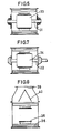
- Fig. 6 shows a section along the line VI-VI in Fig. 1 and shows the pulley 33 with its shaft 31 journalled in e.g. plates moveably arranged outside the side walls of the housing.
- the pulley can have a smooth or bombarded surface and be made of steel, wood or some other material.
- Fig. 7 shows a section along the line VII-VII in Fig. 1 and shows the drive pulley and the drive shaft journalled for instance outside the side walls of the housing.
- the drive pulley can be smooth or bombarded and the drive surface can be friction coated, transversely slotted or have some other friction-promoting form. It can be made of steel, wood or some other material.
- Fig. 8 shows a section along the line VIII-VIII in Fig. 1 and shows a distributor 40 in the inlet 39 to the conveyor in order to guide the material laterally of the upper belt part.
- the distributor can preferably be made of steel or some other material and be fastened to the front and back walls of the inlet.
- Fig. 9 shows one embodiment of a guide means 42 for laterally guiding the material on the upper surface of the lower belt part.
- This guiding means can be made of steel or some other material and be fastened to the side walls of the housing.
- Fig. 10 shows a modified guide means which is openable for letting through the material flow 43 (Fig. 1), if desired.
- the sides 55 of said guide means are pivoted to back flanks 56 and opening-closing takes preferably place by means of air pressure cylinders.
- a belt can have a width corresponding to the width between the side walls of the housing and the gaps or openings 44 can then be formed for instance by widening the side walls outwardly at appropriate positions.
Landscapes
- Engineering & Computer Science (AREA)
- Mechanical Engineering (AREA)
- Structure Of Belt Conveyors (AREA)
- Belt Conveyors (AREA)
- Pusher Or Impeller Conveyors (AREA)
- Formation And Processing Of Food Products (AREA)
- Seasonings (AREA)
- Drying Of Solid Materials (AREA)
- Framework For Endless Conveyors (AREA)
Claims (9)
Priority Applications (1)
| Application Number | Priority Date | Filing Date | Title |
|---|---|---|---|
| AT84901826T ATE38201T1 (de) | 1983-12-21 | 1984-04-13 | Foerderband, insbesondere fuer getreideartige materialien. |
Applications Claiming Priority (2)
| Application Number | Priority Date | Filing Date | Title |
|---|---|---|---|
| SE8307059 | 1983-12-21 | ||
| SE8307059A SE436122B (sv) | 1983-12-21 | 1983-12-21 | Anordning for att festa medbringare vid ett transportband |
Publications (2)
| Publication Number | Publication Date |
|---|---|
| EP0197919A1 EP0197919A1 (de) | 1986-10-22 |
| EP0197919B1 true EP0197919B1 (de) | 1988-10-26 |
Family
ID=20353825
Family Applications (1)
| Application Number | Title | Priority Date | Filing Date |
|---|---|---|---|
| EP84901826A Expired EP0197919B1 (de) | 1983-12-21 | 1984-04-13 | Förderband, insbesondere für getreideartige materialien |
Country Status (8)
| Country | Link |
|---|---|
| EP (1) | EP0197919B1 (de) |
| JP (1) | JPS61500962A (de) |
| AU (1) | AU570045B2 (de) |
| CA (1) | CA1225353A (de) |
| DE (1) | DE3474807D1 (de) |
| DK (1) | DK152029C (de) |
| SE (1) | SE436122B (de) |
| WO (1) | WO1985002831A1 (de) |
Cited By (2)
| Publication number | Priority date | Publication date | Assignee | Title |
|---|---|---|---|---|
| DE19731685A1 (de) * | 1997-07-23 | 1999-01-28 | Karl Beck Gmbh & Co Kg | Vorrichtung zum Transport von Futtermitteln |
| CN102975240A (zh) * | 2012-11-07 | 2013-03-20 | 蒋克红 | 一种碎屑收集装置 |
Families Citing this family (4)
| Publication number | Priority date | Publication date | Assignee | Title |
|---|---|---|---|---|
| JP2002369614A (ja) * | 2001-06-15 | 2002-12-24 | Yanmar Agricult Equip Co Ltd | コンバイン |
| CN102219105A (zh) * | 2010-04-16 | 2011-10-19 | 中粮集团有限公司 | 一种输送装置 |
| US11771006B2 (en) | 2019-07-02 | 2023-10-03 | Monsanto Technology Llc | Plant product harvesting machine feederhouse |
| JP7452631B2 (ja) * | 2020-03-27 | 2024-03-19 | 東レ株式会社 | フライトコンベヤ装置 |
Family Cites Families (7)
| Publication number | Priority date | Publication date | Assignee | Title |
|---|---|---|---|---|
| DE805255C (de) * | 1948-12-23 | 1951-05-10 | Bernhard Beumer | Steilfoerderer mit Mitnehmern |
| FR1067258A (fr) * | 1952-11-28 | 1954-06-14 | Perfectionnement apporté aux dispositifs d'alimentation de soutes individuelles pour sable de fonderie ou matières analogues | |
| GB976668A (en) * | 1962-08-13 | 1964-12-02 | James Baker Conveyors Ltd | Conveyors |
| CA1045073A (en) * | 1976-04-06 | 1978-12-26 | Kaiser Resources Ltd. | Wet belt conveyor |
| CH624359A5 (de) * | 1977-12-14 | 1981-07-31 | Buehler Ag Geb | |
| NL185008C (nl) * | 1979-01-18 | 1990-01-02 | Cehave Nv | Schalmenketting met meenemers voor een kettingtransporteur. |
| DK146531C (da) * | 1980-03-17 | 1984-04-09 | Sn Eng As | Transportoer til transport af forholdsvis tungt massegods |
-
1983
- 1983-12-21 SE SE8307059A patent/SE436122B/sv not_active IP Right Cessation
-
1984
- 1984-04-13 AU AU28674/84A patent/AU570045B2/en not_active Ceased
- 1984-04-13 WO PCT/SE1984/000143 patent/WO1985002831A1/en not_active Ceased
- 1984-04-13 JP JP59501799A patent/JPS61500962A/ja active Pending
- 1984-04-13 DE DE8484901826T patent/DE3474807D1/de not_active Expired
- 1984-04-13 EP EP84901826A patent/EP0197919B1/de not_active Expired
- 1984-04-26 CA CA000452908A patent/CA1225353A/en not_active Expired
- 1984-12-19 DK DK610584A patent/DK152029C/da not_active IP Right Cessation
Cited By (2)
| Publication number | Priority date | Publication date | Assignee | Title |
|---|---|---|---|---|
| DE19731685A1 (de) * | 1997-07-23 | 1999-01-28 | Karl Beck Gmbh & Co Kg | Vorrichtung zum Transport von Futtermitteln |
| CN102975240A (zh) * | 2012-11-07 | 2013-03-20 | 蒋克红 | 一种碎屑收集装置 |
Also Published As
| Publication number | Publication date |
|---|---|
| SE436122B (sv) | 1984-11-12 |
| WO1985002831A1 (en) | 1985-07-04 |
| SE8307059D0 (sv) | 1983-12-21 |
| DE3474807D1 (en) | 1988-12-01 |
| JPS61500962A (ja) | 1986-05-15 |
| DK152029C (da) | 1988-07-18 |
| AU570045B2 (en) | 1988-03-03 |
| SE8307059L (sv) | 1984-10-28 |
| AU2867484A (en) | 1985-07-12 |
| DK152029B (da) | 1988-01-25 |
| CA1225353A (en) | 1987-08-11 |
| DK610584A (da) | 1985-07-04 |
| DK610584D0 (da) | 1984-12-19 |
| EP0197919A1 (de) | 1986-10-22 |
Similar Documents
| Publication | Publication Date | Title |
|---|---|---|
| CN210709404U (zh) | 一种皮带机底部刮料和清扫装置 | |
| US4380284A (en) | Chip conveyer | |
| GB1571233A (en) | Arrangement for conveying and rotating material | |
| EP0197919B1 (de) | Förderband, insbesondere für getreideartige materialien | |
| US5919023A (en) | Compact overhead conveyor | |
| US2795056A (en) | Conveying and treating system for loose, solid materials | |
| US3672334A (en) | Apparatus for distributing animal feed | |
| US3414116A (en) | Conveyor scraper means | |
| US3219173A (en) | Conveyors | |
| GB2189757A (en) | Improvements relating to tensioning devices for use with chain conveyors | |
| US1953245A (en) | Separating conveyer | |
| JPH02100906A (ja) | 人参などのような比較的短くて先細り形状の根葉類供給装置 | |
| US20030079965A1 (en) | Conveyor apparatus for sugar mill intermediates | |
| AT525072A4 (de) | Förderanlage zum Längstransport von länglichem Stückgut | |
| US3055485A (en) | Conveyor system for animal husbandry | |
| DE10146180B4 (de) | Vorrichtung zur mechanischen Reinigung eines Förderbandes | |
| US3111217A (en) | Conveyor chain hold-down means | |
| US2796166A (en) | Apparatus for conveying welding electrodes through a drying stove | |
| US3348660A (en) | Conveyors | |
| CN223673624U (zh) | 一种滚筒落煤收集输送装置 | |
| SE439472B (sv) | Transportor med uppdelade materialstrommar | |
| EP0647202B1 (de) | Anordnung für einen förderer | |
| CN213415329U (zh) | 一种卧式冷却器自动掉渣清除装置 | |
| CN219791506U (zh) | 一种物料自清输送装置 | |
| NO157776B (no) | Transport, sÿrlig for fremfing av kornformet material. |
Legal Events
| Date | Code | Title | Description |
|---|---|---|---|
| PUAI | Public reference made under article 153(3) epc to a published international application that has entered the european phase |
Free format text: ORIGINAL CODE: 0009012 |
|
| 17P | Request for examination filed |
Effective date: 19851019 |
|
| AK | Designated contracting states |
Kind code of ref document: A1 Designated state(s): AT DE FR GB NL |
|
| 17Q | First examination report despatched |
Effective date: 19871012 |
|
| GRAA | (expected) grant |
Free format text: ORIGINAL CODE: 0009210 |
|
| AK | Designated contracting states |
Kind code of ref document: B1 Designated state(s): AT DE FR GB NL |
|
| PG25 | Lapsed in a contracting state [announced via postgrant information from national office to epo] |
Ref country code: NL Effective date: 19881026 Ref country code: FR Free format text: THE PATENT HAS BEEN ANNULLED BY A DECISION OF A NATIONAL AUTHORITY Effective date: 19881026 Ref country code: AT Effective date: 19881026 |
|
| REF | Corresponds to: |
Ref document number: 38201 Country of ref document: AT Date of ref document: 19881115 Kind code of ref document: T |
|
| REF | Corresponds to: |
Ref document number: 3474807 Country of ref document: DE Date of ref document: 19881201 |
|
| NLV1 | Nl: lapsed or annulled due to failure to fulfill the requirements of art. 29p and 29m of the patents act | ||
| EN | Fr: translation not filed | ||
| PG25 | Lapsed in a contracting state [announced via postgrant information from national office to epo] |
Ref country code: GB Effective date: 19890413 |
|
| PLBE | No opposition filed within time limit |
Free format text: ORIGINAL CODE: 0009261 |
|
| STAA | Information on the status of an ep patent application or granted ep patent |
Free format text: STATUS: NO OPPOSITION FILED WITHIN TIME LIMIT |
|
| 26N | No opposition filed | ||
| GBPC | Gb: european patent ceased through non-payment of renewal fee | ||
| PG25 | Lapsed in a contracting state [announced via postgrant information from national office to epo] |
Ref country code: DE Effective date: 19900103 |