EP0197808B1 - Verfahren und Fraktionierungsanlage gasförmiger Ströme - Google Patents
Verfahren und Fraktionierungsanlage gasförmiger Ströme Download PDFInfo
- Publication number
- EP0197808B1 EP0197808B1 EP86400448A EP86400448A EP0197808B1 EP 0197808 B1 EP0197808 B1 EP 0197808B1 EP 86400448 A EP86400448 A EP 86400448A EP 86400448 A EP86400448 A EP 86400448A EP 0197808 B1 EP0197808 B1 EP 0197808B1
- Authority
- EP
- European Patent Office
- Prior art keywords
- column
- refrigerating
- exchange system
- purifying
- cut
- Prior art date
- Legal status (The legal status is an assumption and is not a legal conclusion. Google has not performed a legal analysis and makes no representation as to the accuracy of the status listed.)
- Expired
Links
- 238000000034 method Methods 0.000 title claims description 20
- 238000009434 installation Methods 0.000 title description 40
- 238000005057 refrigeration Methods 0.000 claims description 74
- ATUOYWHBWRKTHZ-UHFFFAOYSA-N Propane Chemical compound CCC ATUOYWHBWRKTHZ-UHFFFAOYSA-N 0.000 claims description 56
- 239000007789 gas Substances 0.000 claims description 39
- 239000001294 propane Substances 0.000 claims description 30
- 238000000605 extraction Methods 0.000 claims description 27
- OTMSDBZUPAUEDD-UHFFFAOYSA-N Ethane Chemical compound CC OTMSDBZUPAUEDD-UHFFFAOYSA-N 0.000 claims description 24
- 239000007788 liquid Substances 0.000 claims description 24
- 239000007791 liquid phase Substances 0.000 claims description 18
- 239000000203 mixture Substances 0.000 claims description 18
- 150000001875 compounds Chemical class 0.000 claims description 17
- 238000010992 reflux Methods 0.000 claims description 16
- 239000012530 fluid Substances 0.000 claims description 15
- VNWKTOKETHGBQD-UHFFFAOYSA-N methane Chemical compound C VNWKTOKETHGBQD-UHFFFAOYSA-N 0.000 claims description 14
- 238000002347 injection Methods 0.000 claims description 12
- 239000007924 injection Substances 0.000 claims description 12
- 239000012071 phase Substances 0.000 claims description 12
- 238000012856 packing Methods 0.000 claims description 11
- VGGSQFUCUMXWEO-UHFFFAOYSA-N Ethene Chemical compound C=C VGGSQFUCUMXWEO-UHFFFAOYSA-N 0.000 claims description 5
- 239000005977 Ethylene Substances 0.000 claims description 5
- 229930195733 hydrocarbon Natural products 0.000 claims description 5
- 150000002430 hydrocarbons Chemical class 0.000 claims description 5
- 238000000926 separation method Methods 0.000 claims description 4
- -1 ethane and propane Chemical class 0.000 claims description 2
- 239000007792 gaseous phase Substances 0.000 claims 6
- 230000003134 recirculating effect Effects 0.000 claims 2
- 239000000126 substance Substances 0.000 claims 2
- 230000000630 rising effect Effects 0.000 claims 1
- 238000005194 fractionation Methods 0.000 description 40
- 239000002912 waste gas Substances 0.000 description 16
- 230000006835 compression Effects 0.000 description 12
- 238000007906 compression Methods 0.000 description 12
- 239000003507 refrigerant Substances 0.000 description 8
- 238000009833 condensation Methods 0.000 description 5
- 230000005494 condensation Effects 0.000 description 5
- 239000001273 butane Substances 0.000 description 4
- 238000001816 cooling Methods 0.000 description 4
- OFBQJSOFQDEBGM-UHFFFAOYSA-N n-pentane Natural products CCCCC OFBQJSOFQDEBGM-UHFFFAOYSA-N 0.000 description 4
- 238000000746 purification Methods 0.000 description 4
- 238000004064 recycling Methods 0.000 description 4
- 239000003345 natural gas Substances 0.000 description 3
- 239000012808 vapor phase Substances 0.000 description 3
- 241000287107 Passer Species 0.000 description 2
- 230000001174 ascending effect Effects 0.000 description 2
- 229910002092 carbon dioxide Inorganic materials 0.000 description 2
- CURLTUGMZLYLDI-UHFFFAOYSA-N carbon dioxide Natural products O=C=O CURLTUGMZLYLDI-UHFFFAOYSA-N 0.000 description 2
- 239000001569 carbon dioxide Substances 0.000 description 2
- 238000001035 drying Methods 0.000 description 2
- IJGRMHOSHXDMSA-UHFFFAOYSA-N nitrogen Substances N#N IJGRMHOSHXDMSA-UHFFFAOYSA-N 0.000 description 2
- 229910052757 nitrogen Inorganic materials 0.000 description 2
- 239000004215 Carbon black (E152) Substances 0.000 description 1
- 239000000945 filler Substances 0.000 description 1
- 238000010438 heat treatment Methods 0.000 description 1
- 239000012263 liquid product Substances 0.000 description 1
- 239000007062 medium k Substances 0.000 description 1
- 239000003208 petroleum Substances 0.000 description 1
- 238000011144 upstream manufacturing Methods 0.000 description 1
Images

Classifications
-
- F—MECHANICAL ENGINEERING; LIGHTING; HEATING; WEAPONS; BLASTING
- F25—REFRIGERATION OR COOLING; COMBINED HEATING AND REFRIGERATION SYSTEMS; HEAT PUMP SYSTEMS; MANUFACTURE OR STORAGE OF ICE; LIQUEFACTION SOLIDIFICATION OF GASES
- F25J—LIQUEFACTION, SOLIDIFICATION OR SEPARATION OF GASES OR GASEOUS OR LIQUEFIED GASEOUS MIXTURES BY PRESSURE AND COLD TREATMENT OR BY BRINGING THEM INTO THE SUPERCRITICAL STATE
- F25J3/00—Processes or apparatus for separating the constituents of gaseous or liquefied gaseous mixtures involving the use of liquefaction or solidification
- F25J3/02—Processes or apparatus for separating the constituents of gaseous or liquefied gaseous mixtures involving the use of liquefaction or solidification by rectification, i.e. by continuous interchange of heat and material between a vapour stream and a liquid stream
- F25J3/0228—Processes or apparatus for separating the constituents of gaseous or liquefied gaseous mixtures involving the use of liquefaction or solidification by rectification, i.e. by continuous interchange of heat and material between a vapour stream and a liquid stream characterised by the separated product stream
- F25J3/0242—Processes or apparatus for separating the constituents of gaseous or liquefied gaseous mixtures involving the use of liquefaction or solidification by rectification, i.e. by continuous interchange of heat and material between a vapour stream and a liquid stream characterised by the separated product stream separation of CnHm with 3 carbon atoms or more
-
- C—CHEMISTRY; METALLURGY
- C07—ORGANIC CHEMISTRY
- C07C—ACYCLIC OR CARBOCYCLIC COMPOUNDS
- C07C7/00—Purification; Separation; Use of additives
- C07C7/09—Purification; Separation; Use of additives by fractional condensation
-
- F—MECHANICAL ENGINEERING; LIGHTING; HEATING; WEAPONS; BLASTING
- F25—REFRIGERATION OR COOLING; COMBINED HEATING AND REFRIGERATION SYSTEMS; HEAT PUMP SYSTEMS; MANUFACTURE OR STORAGE OF ICE; LIQUEFACTION SOLIDIFICATION OF GASES
- F25J—LIQUEFACTION, SOLIDIFICATION OR SEPARATION OF GASES OR GASEOUS OR LIQUEFIED GASEOUS MIXTURES BY PRESSURE AND COLD TREATMENT OR BY BRINGING THEM INTO THE SUPERCRITICAL STATE
- F25J3/00—Processes or apparatus for separating the constituents of gaseous or liquefied gaseous mixtures involving the use of liquefaction or solidification
- F25J3/02—Processes or apparatus for separating the constituents of gaseous or liquefied gaseous mixtures involving the use of liquefaction or solidification by rectification, i.e. by continuous interchange of heat and material between a vapour stream and a liquid stream
- F25J3/0204—Processes or apparatus for separating the constituents of gaseous or liquefied gaseous mixtures involving the use of liquefaction or solidification by rectification, i.e. by continuous interchange of heat and material between a vapour stream and a liquid stream characterised by the feed stream
- F25J3/0209—Natural gas or substitute natural gas
-
- F—MECHANICAL ENGINEERING; LIGHTING; HEATING; WEAPONS; BLASTING
- F25—REFRIGERATION OR COOLING; COMBINED HEATING AND REFRIGERATION SYSTEMS; HEAT PUMP SYSTEMS; MANUFACTURE OR STORAGE OF ICE; LIQUEFACTION SOLIDIFICATION OF GASES
- F25J—LIQUEFACTION, SOLIDIFICATION OR SEPARATION OF GASES OR GASEOUS OR LIQUEFIED GASEOUS MIXTURES BY PRESSURE AND COLD TREATMENT OR BY BRINGING THEM INTO THE SUPERCRITICAL STATE
- F25J3/00—Processes or apparatus for separating the constituents of gaseous or liquefied gaseous mixtures involving the use of liquefaction or solidification
- F25J3/02—Processes or apparatus for separating the constituents of gaseous or liquefied gaseous mixtures involving the use of liquefaction or solidification by rectification, i.e. by continuous interchange of heat and material between a vapour stream and a liquid stream
- F25J3/0228—Processes or apparatus for separating the constituents of gaseous or liquefied gaseous mixtures involving the use of liquefaction or solidification by rectification, i.e. by continuous interchange of heat and material between a vapour stream and a liquid stream characterised by the separated product stream
- F25J3/0233—Processes or apparatus for separating the constituents of gaseous or liquefied gaseous mixtures involving the use of liquefaction or solidification by rectification, i.e. by continuous interchange of heat and material between a vapour stream and a liquid stream characterised by the separated product stream separation of CnHm with 1 carbon atom or more
-
- F—MECHANICAL ENGINEERING; LIGHTING; HEATING; WEAPONS; BLASTING
- F25—REFRIGERATION OR COOLING; COMBINED HEATING AND REFRIGERATION SYSTEMS; HEAT PUMP SYSTEMS; MANUFACTURE OR STORAGE OF ICE; LIQUEFACTION SOLIDIFICATION OF GASES
- F25J—LIQUEFACTION, SOLIDIFICATION OR SEPARATION OF GASES OR GASEOUS OR LIQUEFIED GASEOUS MIXTURES BY PRESSURE AND COLD TREATMENT OR BY BRINGING THEM INTO THE SUPERCRITICAL STATE
- F25J3/00—Processes or apparatus for separating the constituents of gaseous or liquefied gaseous mixtures involving the use of liquefaction or solidification
- F25J3/02—Processes or apparatus for separating the constituents of gaseous or liquefied gaseous mixtures involving the use of liquefaction or solidification by rectification, i.e. by continuous interchange of heat and material between a vapour stream and a liquid stream
- F25J3/0228—Processes or apparatus for separating the constituents of gaseous or liquefied gaseous mixtures involving the use of liquefaction or solidification by rectification, i.e. by continuous interchange of heat and material between a vapour stream and a liquid stream characterised by the separated product stream
- F25J3/0238—Processes or apparatus for separating the constituents of gaseous or liquefied gaseous mixtures involving the use of liquefaction or solidification by rectification, i.e. by continuous interchange of heat and material between a vapour stream and a liquid stream characterised by the separated product stream separation of CnHm with 2 carbon atoms or more
-
- F—MECHANICAL ENGINEERING; LIGHTING; HEATING; WEAPONS; BLASTING
- F25—REFRIGERATION OR COOLING; COMBINED HEATING AND REFRIGERATION SYSTEMS; HEAT PUMP SYSTEMS; MANUFACTURE OR STORAGE OF ICE; LIQUEFACTION SOLIDIFICATION OF GASES
- F25J—LIQUEFACTION, SOLIDIFICATION OR SEPARATION OF GASES OR GASEOUS OR LIQUEFIED GASEOUS MIXTURES BY PRESSURE AND COLD TREATMENT OR BY BRINGING THEM INTO THE SUPERCRITICAL STATE
- F25J2200/00—Processes or apparatus using separation by rectification
- F25J2200/04—Processes or apparatus using separation by rectification in a dual pressure main column system
-
- F—MECHANICAL ENGINEERING; LIGHTING; HEATING; WEAPONS; BLASTING
- F25—REFRIGERATION OR COOLING; COMBINED HEATING AND REFRIGERATION SYSTEMS; HEAT PUMP SYSTEMS; MANUFACTURE OR STORAGE OF ICE; LIQUEFACTION SOLIDIFICATION OF GASES
- F25J—LIQUEFACTION, SOLIDIFICATION OR SEPARATION OF GASES OR GASEOUS OR LIQUEFIED GASEOUS MIXTURES BY PRESSURE AND COLD TREATMENT OR BY BRINGING THEM INTO THE SUPERCRITICAL STATE
- F25J2200/00—Processes or apparatus using separation by rectification
- F25J2200/50—Processes or apparatus using separation by rectification using multiple (re-)boiler-condensers at different heights of the column
-
- F—MECHANICAL ENGINEERING; LIGHTING; HEATING; WEAPONS; BLASTING
- F25—REFRIGERATION OR COOLING; COMBINED HEATING AND REFRIGERATION SYSTEMS; HEAT PUMP SYSTEMS; MANUFACTURE OR STORAGE OF ICE; LIQUEFACTION SOLIDIFICATION OF GASES
- F25J—LIQUEFACTION, SOLIDIFICATION OR SEPARATION OF GASES OR GASEOUS OR LIQUEFIED GASEOUS MIXTURES BY PRESSURE AND COLD TREATMENT OR BY BRINGING THEM INTO THE SUPERCRITICAL STATE
- F25J2200/00—Processes or apparatus using separation by rectification
- F25J2200/70—Refluxing the column with a condensed part of the feed stream, i.e. fractionator top is stripped or self-rectified
-
- F—MECHANICAL ENGINEERING; LIGHTING; HEATING; WEAPONS; BLASTING
- F25—REFRIGERATION OR COOLING; COMBINED HEATING AND REFRIGERATION SYSTEMS; HEAT PUMP SYSTEMS; MANUFACTURE OR STORAGE OF ICE; LIQUEFACTION SOLIDIFICATION OF GASES
- F25J—LIQUEFACTION, SOLIDIFICATION OR SEPARATION OF GASES OR GASEOUS OR LIQUEFIED GASEOUS MIXTURES BY PRESSURE AND COLD TREATMENT OR BY BRINGING THEM INTO THE SUPERCRITICAL STATE
- F25J2200/00—Processes or apparatus using separation by rectification
- F25J2200/74—Refluxing the column with at least a part of the partially condensed overhead gas
-
- F—MECHANICAL ENGINEERING; LIGHTING; HEATING; WEAPONS; BLASTING
- F25—REFRIGERATION OR COOLING; COMBINED HEATING AND REFRIGERATION SYSTEMS; HEAT PUMP SYSTEMS; MANUFACTURE OR STORAGE OF ICE; LIQUEFACTION SOLIDIFICATION OF GASES
- F25J—LIQUEFACTION, SOLIDIFICATION OR SEPARATION OF GASES OR GASEOUS OR LIQUEFIED GASEOUS MIXTURES BY PRESSURE AND COLD TREATMENT OR BY BRINGING THEM INTO THE SUPERCRITICAL STATE
- F25J2200/00—Processes or apparatus using separation by rectification
- F25J2200/76—Refluxing the column with condensed overhead gas being cycled in a quasi-closed loop refrigeration cycle
-
- F—MECHANICAL ENGINEERING; LIGHTING; HEATING; WEAPONS; BLASTING
- F25—REFRIGERATION OR COOLING; COMBINED HEATING AND REFRIGERATION SYSTEMS; HEAT PUMP SYSTEMS; MANUFACTURE OR STORAGE OF ICE; LIQUEFACTION SOLIDIFICATION OF GASES
- F25J—LIQUEFACTION, SOLIDIFICATION OR SEPARATION OF GASES OR GASEOUS OR LIQUEFIED GASEOUS MIXTURES BY PRESSURE AND COLD TREATMENT OR BY BRINGING THEM INTO THE SUPERCRITICAL STATE
- F25J2200/00—Processes or apparatus using separation by rectification
- F25J2200/78—Refluxing the column with a liquid stream originating from an upstream or downstream fractionator column
-
- F—MECHANICAL ENGINEERING; LIGHTING; HEATING; WEAPONS; BLASTING
- F25—REFRIGERATION OR COOLING; COMBINED HEATING AND REFRIGERATION SYSTEMS; HEAT PUMP SYSTEMS; MANUFACTURE OR STORAGE OF ICE; LIQUEFACTION SOLIDIFICATION OF GASES
- F25J—LIQUEFACTION, SOLIDIFICATION OR SEPARATION OF GASES OR GASEOUS OR LIQUEFIED GASEOUS MIXTURES BY PRESSURE AND COLD TREATMENT OR BY BRINGING THEM INTO THE SUPERCRITICAL STATE
- F25J2205/00—Processes or apparatus using other separation and/or other processing means
- F25J2205/02—Processes or apparatus using other separation and/or other processing means using simple phase separation in a vessel or drum
- F25J2205/04—Processes or apparatus using other separation and/or other processing means using simple phase separation in a vessel or drum in the feed line, i.e. upstream of the fractionation step
-
- F—MECHANICAL ENGINEERING; LIGHTING; HEATING; WEAPONS; BLASTING
- F25—REFRIGERATION OR COOLING; COMBINED HEATING AND REFRIGERATION SYSTEMS; HEAT PUMP SYSTEMS; MANUFACTURE OR STORAGE OF ICE; LIQUEFACTION SOLIDIFICATION OF GASES
- F25J—LIQUEFACTION, SOLIDIFICATION OR SEPARATION OF GASES OR GASEOUS OR LIQUEFIED GASEOUS MIXTURES BY PRESSURE AND COLD TREATMENT OR BY BRINGING THEM INTO THE SUPERCRITICAL STATE
- F25J2230/00—Processes or apparatus involving steps for increasing the pressure of gaseous process streams
- F25J2230/60—Processes or apparatus involving steps for increasing the pressure of gaseous process streams the fluid being hydrocarbons or a mixture of hydrocarbons
-
- F—MECHANICAL ENGINEERING; LIGHTING; HEATING; WEAPONS; BLASTING
- F25—REFRIGERATION OR COOLING; COMBINED HEATING AND REFRIGERATION SYSTEMS; HEAT PUMP SYSTEMS; MANUFACTURE OR STORAGE OF ICE; LIQUEFACTION SOLIDIFICATION OF GASES
- F25J—LIQUEFACTION, SOLIDIFICATION OR SEPARATION OF GASES OR GASEOUS OR LIQUEFIED GASEOUS MIXTURES BY PRESSURE AND COLD TREATMENT OR BY BRINGING THEM INTO THE SUPERCRITICAL STATE
- F25J2235/00—Processes or apparatus involving steps for increasing the pressure or for conveying of liquid process streams
- F25J2235/60—Processes or apparatus involving steps for increasing the pressure or for conveying of liquid process streams the fluid being (a mixture of) hydrocarbons
-
- F—MECHANICAL ENGINEERING; LIGHTING; HEATING; WEAPONS; BLASTING
- F25—REFRIGERATION OR COOLING; COMBINED HEATING AND REFRIGERATION SYSTEMS; HEAT PUMP SYSTEMS; MANUFACTURE OR STORAGE OF ICE; LIQUEFACTION SOLIDIFICATION OF GASES
- F25J—LIQUEFACTION, SOLIDIFICATION OR SEPARATION OF GASES OR GASEOUS OR LIQUEFIED GASEOUS MIXTURES BY PRESSURE AND COLD TREATMENT OR BY BRINGING THEM INTO THE SUPERCRITICAL STATE
- F25J2240/00—Processes or apparatus involving steps for expanding of process streams
- F25J2240/02—Expansion of a process fluid in a work-extracting turbine (i.e. isentropic expansion), e.g. of the feed stream
-
- F—MECHANICAL ENGINEERING; LIGHTING; HEATING; WEAPONS; BLASTING
- F25—REFRIGERATION OR COOLING; COMBINED HEATING AND REFRIGERATION SYSTEMS; HEAT PUMP SYSTEMS; MANUFACTURE OR STORAGE OF ICE; LIQUEFACTION SOLIDIFICATION OF GASES
- F25J—LIQUEFACTION, SOLIDIFICATION OR SEPARATION OF GASES OR GASEOUS OR LIQUEFIED GASEOUS MIXTURES BY PRESSURE AND COLD TREATMENT OR BY BRINGING THEM INTO THE SUPERCRITICAL STATE
- F25J2270/00—Refrigeration techniques used
- F25J2270/02—Internal refrigeration with liquid vaporising loop
-
- F—MECHANICAL ENGINEERING; LIGHTING; HEATING; WEAPONS; BLASTING
- F25—REFRIGERATION OR COOLING; COMBINED HEATING AND REFRIGERATION SYSTEMS; HEAT PUMP SYSTEMS; MANUFACTURE OR STORAGE OF ICE; LIQUEFACTION SOLIDIFICATION OF GASES
- F25J—LIQUEFACTION, SOLIDIFICATION OR SEPARATION OF GASES OR GASEOUS OR LIQUEFIED GASEOUS MIXTURES BY PRESSURE AND COLD TREATMENT OR BY BRINGING THEM INTO THE SUPERCRITICAL STATE
- F25J2270/00—Refrigeration techniques used
- F25J2270/12—External refrigeration with liquid vaporising loop
-
- F—MECHANICAL ENGINEERING; LIGHTING; HEATING; WEAPONS; BLASTING
- F25—REFRIGERATION OR COOLING; COMBINED HEATING AND REFRIGERATION SYSTEMS; HEAT PUMP SYSTEMS; MANUFACTURE OR STORAGE OF ICE; LIQUEFACTION SOLIDIFICATION OF GASES
- F25J—LIQUEFACTION, SOLIDIFICATION OR SEPARATION OF GASES OR GASEOUS OR LIQUEFIED GASEOUS MIXTURES BY PRESSURE AND COLD TREATMENT OR BY BRINGING THEM INTO THE SUPERCRITICAL STATE
- F25J2270/00—Refrigeration techniques used
- F25J2270/66—Closed external refrigeration cycle with multi component refrigerant [MCR], e.g. mixture of hydrocarbons
-
- F—MECHANICAL ENGINEERING; LIGHTING; HEATING; WEAPONS; BLASTING
- F25—REFRIGERATION OR COOLING; COMBINED HEATING AND REFRIGERATION SYSTEMS; HEAT PUMP SYSTEMS; MANUFACTURE OR STORAGE OF ICE; LIQUEFACTION SOLIDIFICATION OF GASES
- F25J—LIQUEFACTION, SOLIDIFICATION OR SEPARATION OF GASES OR GASEOUS OR LIQUEFIED GASEOUS MIXTURES BY PRESSURE AND COLD TREATMENT OR BY BRINGING THEM INTO THE SUPERCRITICAL STATE
- F25J2270/00—Refrigeration techniques used
- F25J2270/90—External refrigeration, e.g. conventional closed-loop mechanical refrigeration unit using Freon or NH3, unspecified external refrigeration
- F25J2270/902—Details about the refrigeration cycle used, e.g. composition of refrigerant, arrangement of compressors or cascade, make up sources, use of reflux exchangers etc.
Definitions
- the present invention essentially relates to a process for the cryogenic fractionation of any gaseous feeds and such as for example natural gases, gases associated with hydrocarbon condensates, or gases resulting from the treatment of petroleum fractions.
- the invention also relates to an installation for implementing this method.
- the gaseous charge is partially condensed by cooling at low temperature and then separated in a separator flask. Then, the liquid part is treated in a conventional fractionation column, and the heavy compound (s) of the filler which one wishes to obtain is recovered at the bottom of this column in liquid form.
- a refrigeration cycle can be provided to meet the cooling requirements of the installation.
- this kind of installation does not make it possible to extract more than 95% of the propane or more than 85% of the ethane contained in the charge, and therefore does not have an excellent yield.
- This process is further characterized by the fact that, in the case where it is desired to extract the C 2 + cut, the gaseous charge, after at least partial condensation in the exchange system, is separated on the one hand into a phase liquid injected into the middle of the fractionation column and on the other hand into a gas phase which is at least partially condensed in said exchange system, then injected into the purification-refrigeration column, while, in the case of extraction of the C 3 + cut, said partially condensed gas charge in the refrigerated exchange system is injected directly and without separation into the purification-refrigeration column.
- a fluid composed of a mixture of light hydrocarbons such as ethane and propane, molecular weight between 30 and 40, or a pure propane type body preferably used.
- a fluid composed of a mixture of light hydrocarbons such as methane, ethylene, ethane or propane, of molecular weight between 26 and 36 or a fluid composed of a pure ethylene or ethane type body.
- the derived gaseous charge is mixed with the remaining part of the gaseous charge previously and partially condensed in the exchange system, the mixture obtained is separated into a liquid phase and a gas phase, and the liquid phase is sub-cooled in the exchange system, while the gas phase is expanded and then mixed with said liquid phase sub-cooled to constitute a mixed phase which is injected into the purification-refrigeration column under the upper packing bed, while, in the case where it is desired to extract the C 3 + cut, the charge gas is not derived but condensed directly and partially in the exchange system, after which it undergoes the aforementioned separation to form a gas phase which, after the above expansion, is injected directly into the column of purif ication-refrigeration under the upper packing bed, and a liquid phase injected directly into said purification-cooling column under
- the aforementioned fractionation column operates at a pressure higher than that of the purification column -refrigeration to ensure the injection of the distillate from the fractionation column, condensed or not, into the purification-refrigeration column.
- the gaseous charge condensed at least partially in the exchange system is sent to a separator comprising at the bottom a pipe connected directly and preferably to the middle of the fractionation column in order to inject the separated liquid phase therein, and at the head a conduit for the separate gas phase which crosses said exchange system and which is followed by a conduit connected to the purification-refrigeration column for injecting said partially condensed gas phase, while a means, such as valves by example, is provided to short-circuit said separator.
- the above-mentioned exchange system incorporates two closed and independent refrigeration circuits operating respectively at a single pressure level and at one or more pressure levels.
- this installation is characterized by a pipe for bypassing the gas charge, connected to a reboiling system associated with the fractionation column and joined with a pipe through which the remaining part of the gas charge passes, the meeting of said lines communicating with a separator, the bottom of which comprises a flow path for the liquid fraction divided into two paths, one of which is connected to said exchange system and the other of which is directly connected to the purification-refrigeration column , while the head of the separator is connected by a pipe to the inlet of a turbo-expander, the outlet of which is connected to one of the aforementioned flow paths so as to constitute a mixture injected by a duct into the column of purification-refrigeration to which said conduit is connected.
- the exchange system consists of at least one plate exchanger in which the fluids which cool are descending and the fluids which heat are ascending.
- the purification-refrigeration column is advantageously associated with a reboiler which is part of the exchange system.
- the permutation of the extraction of the C 3 + cup with the extraction of the C 3 + cup is quite simply carried out using manual or motorized valves interposed on the above-mentioned lines.
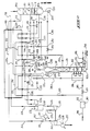
- the gaseous charge to be treated reaches the installation via a pipe 106 connected to a drying unit 107 which is followed by a passageway 108 passing through the exchange system 103 and ending at a separator 109 by a portion of pipe 110.
- the bottom of the separator 109 is connected by a line 111 directly and preferably in the middle of the fractionation column 102.
- the head of the separator is provided with a line 112, a portion 113 of which passes through the exchange system 103 and is extended by the pipe portion visible at 114 and allowing the injection of the partially condensed gas phase at the bottom of the purification-refrigeration column.
- a valve V1 is provided on the pipe portion 110, and, as will be seen below, the separator 109 can be short-circuited by a pipe 115 connecting the pipe portion 110 to the pipe 113 and equipped with a valve V2.
- the gaseous distillate at the head 102a of the fractionation column 102 is conveyed by a pipe 116 passing through the exchange system 103 to a reflux flask 117.
- This reflux flask has at its head a conduit 118 for supplying gaseous distillate which is cooled in the exchange system 103 passing through the pipe portion 119 to be at least partially condensed and thus injected by the pipe portion 120 at the head 101a of the purification-refrigeration column 101.
- the reflux tank 117 comprises at bottom a second conduit 121 equipped with a pump 122 and ensuring by the flow path 123 the reflux at the head 102a of the column 102.
- a conduit 124 constituting a bypass of the conduit 116 allows the injection of the distillate. from the fractionation column 102 directly and without passing through the exchange system 103, in the bottom 101 b of the purification-refrigeration column 101.
- the liquid leaving the pump 126 is conveyed to the column 102 by a conduit 127 which divides at point 128 into two conduits and namely a conduit 129 connected directly and without pass through the exchange system 103 at the head 102a of the fractionation column 102 via 123, and a conduit 130 comprising a portion of conduit 131 passing through the exchange system 103, and to which follows another portion of conduit 132 connected substantially in the middle of the fractionation column 102.
- the waste gas leaving at the head 101a a from the column 101 passes through a pipe 133, a portion 134 of which crosses the exchange system 103 and is then connected to a compression unit 135, after which the waste gas is discharged through a pipe 136.
- a pipe 137 connected to the compression unit 135 allows the recirculation of the compressed waste gas, this pipe passing through a portion 138 through the exchange system 103 and being connected at 139 to the pipe 120 for reflux of the distillate. from the fractionation column 102 to the head of the purification-refrigeration column 101.
- the closed refrigeration circuit 105 comprises a compressor 140, the discharge of which is connected by a pipe 141 to a condenser with refrigerant of external origin.
- This condenser 142 is connected by a pipe 143 passing through the exchanger 103 to a receiver flask 144.
- the bottom of this flask has a pipe 145 which passes through the exchanger 103 to sub-cool the separated liquid phase.
- This pipe 145 is divided into two tracks 145a, 145b, each equipped with an expansion valve D 1 , D 2 .
- the liquid phase is thus vaporized at two pressure levels before reaching respectively through the pipes 146, 147 passing through the exchanger 103 to balloons 148, 149 which are in turn respectively connected by the pipes 140a and 140b to the floor intermediate and low pressure stage of compressor 140.
- the other closed refrigeration circuit 104 associated with the exchanger 103 essentially comprises a compressor 150 whose outlet is connected by a line 151 to a condenser 152 with refrigerant of external origin.
- the outlet of this condenser 152 is equipped with a pipe 153 which passes through its portion 154 the exchanger 103 and ends at a receiving flask 155.
- the bottom of this flask comprises a pipe 156 passing through the exchanger 103, then leaving this exchanger by a section of pipe visible at 157 and provided with an expansion valve D 3 .
- the sub-cooled liquid phase coming from the balloon 155 is expanded and vaporized in the pipe portion 156a in order to reach a balloon 158 connected by the pipe 150a to the suction of the compressor 150.
- a reboiler 159, 160 is associated with the bottom of the purification-refrigeration column 101, this reboiler being part of the exchange system 103, according to the example shown in FIG. 1.
- the liquid product collected at the bottom 102b of the fractionation column 102 is discharged through a line 166 via a pump 167.
- valve V3 on line 129
- valve V4 on line 124
- valve V5 on line 137
- valve V6 on line 111
- valve V7 on line line 130
- valve V8 on line 116
- valve V9 on line 123
- valve V10 on the external fluid supply to reboiler 165.
- This gas is initially at a pressure of 30 bars and has a temperature of 15 ° C.
- valves V1, V3, V4, V5 and V6 are closed, and all the other valves are open.
- the dried gaseous charge is refrigerated at high pressure in the exchange system 103 which is constituted by a plate exchanger in which the fluids which cool are descending and the fluids which heat are ascending. More specifically, the dried gas passes through lines 108 and 113 (valve V1 closed and valve V2 open), where it is cooled to -68 ° C. Then the gaseous charge is introduced via line 114 at the bottom 101b of the purification-refrigeration column where it contacts the reflux 120 constituted by the gaseous distillate 118 partially condensed at 119 at -70 ° C.
- the condensates collected at 125 at the bottom of the purification column 101 are pumped at 126 and then reheated via the pipe 131 at 10 ° C. at 30.3 bars before feeding the fractionation column 102 through line 132.
- the head 102a of the fractionation column 102 comprises a condensation system integrated into the exchange system 103 or else internal to said column, so that the distillates which exit therefrom via line 116 are condensed at -31 ° C., then introduced in the flask 117 in order to produce the gaseous reflux passing through the line 118, and the liquid reflux passing through the line 121, the pump 122 and the line 123 so as to return to the head 102a of the column 102.
- the waste gas leaving the purification-refrigeration column 101 via line 133 recovers frigories passing through line 134 passing through the exchanger 103, to be sent at 45 ° C in the compression section 135, 136 where it is brought to a pressure of 65 bars.
- Reboiling of the fractionation column 102 is ensured by the external fluid passing through the reboiler 165, and the cut C 3 + obtained at the bottom 102b of the column 102 is available at a pressure of 30.5 bars and at a temperature of 60 ° C. It will be noted here that in the case of the propane extraction which is presently described, the reboilers 161, 162 on the one hand and 163, 164 on the other hand are not used. The same applies to the separator 109 as seen above.
- the refrigeration cycle 105 preferably using a cooling mixture of ethane (47 mol%) and propane (53 mol%).
- This mixture at the outlet of the compressor 140, is at a pressure of 30 bars and is partially condensed in the air cooler 142 at 49 ° C., then is completely condensed in the hot upper part of the exchanger 103 before being introduced into the recipe flask 144.
- the liquid from this flask is sub-cooled in the exchanger 103 then expanded and cooled to two different pressure levels (flow 146 and 147), this in order to ensure the necessary refrigeration.
- valves V2, V7, V8, V9 and V10 it is only necessary to close the valves V2, V7, V8, V9 and V10, while all the other valves V1, V3, V4, V5 and V6 are open.
- the dried gas charge at 107 is cooled to -60 ° C at high pressure, passing through line 108 in the plate exchanger 103, then said charge is introduced into the separator tank 109 (valve V1 open and valve V2 closed).
- the liquid phase 111 is directly injected into the column 102.
- the vapor phase 112 passing through the line 113 is cooled to ⁇ 91.7 ° C and introduced through the line 114 at the bottom of the purification-refrigeration column 101 where it contacts the at least partially condensed refrigerant 120 which, as we saw above, consists of the recycling at high pressure (43.7 bars) of a fraction 137 of the residual gas taken from the intermediate stage of the section of compression 135, 136 which fraction is completely condensed at 138 in the exchanger 103 before arriving at column 101 via line 120.
- the flow at the bottom of the column 101 is heated and partially vaporized in the exchange system 103 (pipes 159, 160), in order to ensure reboiling of said column 101.
- the liquid from the bottom of this column is sent by the pump 126 directly to the head 102a of the fractionation column 102, via the conduits 127 and 129 (valve V3 open, valve V7 closed).
- the intermediate reboiler 161, 162 makes it possible to recover additional frigories, while the reboiling 163, 164 of the column 102 is provided in the hot upper part of the exchanger 103, up to 20 ° C.
- the cut C 2 + is collected in 166 at a temperature of 20 ° C. under 30 bars, and the head 102a of the column 102 directly feeds the bottom of the purification-refrigeration column 101 by means of the pipe 124 (valve V4 open and valve V8 closed).
- the waste gas leaving column 101 via line 133 recovers frigories in the exchanger 103 by passage through line 134 and is sent to 40 ° C in the compression section 135, 136 to be brought to a pressure of 65 bars .
- the refrigeration necessary for the operation of the unit to extract the cut C 2 + is provided by the refrigeration cycle 105, and also by the refrigeration cycle 104.
- the refrigeration cycle 104 preferably uses a refrigerant mixture of ethylene (99 mol%) and propane (1 mol%).
- this refrigerant mixture When the compressor 150 is discharged, this refrigerant mixture is at a pressure of 13 bars and is cooled to 49 ° C in the air cooler 152. Then, thanks to the refrigeration cycle 105, the above-mentioned refrigerant mixture is completely condensed when it reaches the recipe flask 155. The liquid 156 from this flask is then sub-cooled to - 94 ° C passing through the exchanger 103, then expanded to 1.6 bar (D 3 ) and vaporized to -65 ° C to ensure the necessary refrigeration of the lower and cold part of the exchanger 103.
- the refrigerant mixture circulating in the circuit 105 is preferably constituted by a mixture of ethane (50 mol%) and propane (50 mol%) .
- this installation essentially comprises a column 101 for purification-refrigeration by contact, a fractionation column 102 and an exchange system 103.
- column 101 comprises an upper packing bed L, and at least one median lining bed L 2 and lower L 3
- the fractionation column 102 comprises at least one upper lining bed L, o , median L l , and lower L 12 .
- This installation like the one represented in FIG. 1, alone allows, using simple adjustments, to pass from one type of extraction to another, that is to say the extraction of a C 3 + cut on extraction of a C 2 + cut.
- the gaseous charge reaches the installation via a line 200 connected to a drying unit 201 equipped with an outlet channel 202 for the dried gas, which channel is divided into two lines and namely: a line 203 which is followed by a portion 204 of the exchange system 103 itself followed by a portion of pipe 204a; and a bypass line 205 passing through a reboiling system 206 associated with the fractionation column 102, said line 205 extending by a portion 205a which terminates in a phase separator 207.
- the portion of line 204a is connected at 208 to the portion line 205a upstream of the separator 207 to form a single line 209 communicating with said separator.
- the bottom of the separator 207 comprises a flow path 210 which is divided into two paths, namely a path 211 passing through the exchange system 103 and a path 212 directly connected to the purification-refrigeration column 101.
- the head of the separator 207 is connected by a pipe 213 to the inlet of a turbo-expander 214, the outlet of which is connected by a pipe 215 to the flow path 211 mentioned above. More specifically, the path 211 leaving the exchange system 103 is connected to the pipe 215 at point 216 so as to produce a mixture injected by a single pipe 217 into the column 101 of purification-refrigeration by contact.
- This column is equipped with a reboiling system formed by the pipes 218, 219 forming a loop passing through the exchange system 103.
- the head 102a of the fractionation column 102 comprises a path 220 for distillate flow, which path is divided into two pipes, namely a pipe 221 which does not pass through the exchange system 103 and which allows injection distillate directly at the bottom 101b of the purification-refrigeration column 101, and a line 222 connected to the portion 223 of the exchange system 103.
- the portion 223 of said exchange system is connected by a line 224 to a reflux balloon 225.
- the bottom of this reflux balloon is connected by a line 227 via a pump 226 to the head 102a of the column 102 in which is thus injected the liquid phase of the balloon 225.
- the gas phase of the balloon 225 is conveyed by a line 228 to a portion 228a of the exchange system 103, then it is injected by a line 229 at the head 101a of the purification-refrigeration column 101.
- the head 101a of this column is connected to a pipe 230 which ensures the passage of the waste gas through the exchanger 103, then, at the outlet of the exchanger 103, the pipe 231 is connected to the suction of a compressor 232 coupled to the turbo-expander 214, as shown diagrammatically in 233.
- the discharge of the compressor 232 is connected by a pipe 234 to the suction of the first stage 235 of the compression section, then transferred by a pipe 239 via an exchanger 241 to the second stage 236 of the compression section, the waste gas being evacuated by a pipe 237 provided with a final heat-exchanger system 238.
- the outlet pipe 242 of the exchanger 241 is divided into two branches and namely a pipe 243 connected to the suction of the second compression stage 236 and a pipe 244 for recycling the waste gas, followed by a portion 245 of the exchange system 103, itself followed by a pipe 246 connected to the head 101a of the purification-refrigeration column 101.
- the liquid at the bottom 101 b of this column is collected in a pipe 247 provided with a pump 248, the outlet of which is equipped with a pipe 249 which is divided into two flow paths and namely a pipe 250 directly connected to the head of the fractionation column 102 and a conduit 251 followed by a portion 252 of the exchange system 103 and to which follows a conduit 253 connected substantially in the middle of said column 102.
- a reboiler 255 is associated with the bottom 102b of the column 102, and the heavy compounds collected at the bottom of this column are discharged through a line 256.
- the installation which has just been described comprises a plurality of valves with manual or motorized control, which allow the operation of the installation so as to extract either the C 3 + cut or the C 3 + cut.
- a valve V11 on the bypass line 205 a valve V12 on the line 221, a valve V13 on the line 250, a valve V14 on the line 211, a valve V15 on line 244, a valve V16 on the passageway for the external fluid in the reboiler 255, a valve V17 on the line 222, a valve V18 on the line 251, a valve V19 on the reboiler 218-219, and a valve V20 on line 212.
- This gas is introduced into the installation via line 200 at a temperature of 15 ° C. under a pressure of 50 bars.
- valves V11, V12, V13, V14 and V15 are closed, while the valves V16, V17, V18, V19 and V20 are open.
- the gaseous charge dried at 15 ° C and high pressure in 201 flows in the conduits 202 and 203 then is partially condensed at 204 in the plate exchanger 103 to a temperature of -40 ° C, after which it is introduced into the separator flask 207.
- the liquid phase coming from this flask flows in the line 212 where it is expanded to 20 bars and feeds the purification-refrigeration column 101 under the median packing bed L z .
- the vapor phase 213 from the balloon 207 is expanded in the turbo-expander 214 up to 20 bars to reach a temperature of -76 ° C. It is then injected into column 101 through lines 215 and 217, said column 101 being scalded in the cold section of the exchanger 103 (flow 218, 219) from -73 to ⁇ 60 ° C.
- this column 101 the gaseous charge contacts the reflux 229 injected at the top 101a, this reflux being constituted by the gaseous distillate from the flask 225 and completely condensed at -78 ° C in the line 228 passing through the exchanger 103.
- the waste gas from column 101 and leaving via line 230 is heated in exchanger 103 until it reaches a temperature of 41.5 ° C, and it is then sent via line 231 into the compressor 232 coupled to the turbo - expander 214.
- the waste gas then passing through line 234 is compressed in two stages 235 and 236 of the compression section to a pressure of 66.4 bars, while the intermediate coolant-exchanger 241 makes it possible to bring the gas passing through line 239 from 101 ° C to 49 ° C.
- the waste gas is cooled in the final heat-exchanger 238 before being discharged at a pressure of 66 bars.
- the condensates at the bottom of the purification-refrigeration column 101 are discharged by the pump 248 into the conduit 249 at a pressure of 22 bars, then conveyed by the conduit 251, in the portion 252 of the exchanger 103, to be reheated there. up to a temperature of 13.5 ° C, before feeding 253, the fraction column 102 under the Lio upper upholstery bed.
- the distillate at the head 102a of the column 102 is sent via the lines 220, 222 to the exchanger 103, where it is at least partially condensed in 223 at -23.5 ° C., then introduced via the line 224 into the flask 225 in order to produce a liquid reflux 227 injected at the head of the column 102 and a gaseous distillate sent at the head 101a of the column 101 via the line 229, after total condensation in the portion 228a of the exchanger 103-, as explained above.
- the reboiling of the column 102 will be provided by an external fluid passing through the reboiler 255 (valve V16 open), and the section C3 + collected in the line 256 will be at a temperature of 75.6 ° C., and at a pressure of 22 bars.
- valves V11, V12, V13, V14 and V15 are open, while the valves V16, V17, V18, V19 and V20 are closed.
- the gaseous charge dried in 201 at high pressure and at 15 ° C separates into two streams 203 and 205.
- the stream 205 is partially condensed in 205a at ⁇ 62 ° C by reboiling the fractionation column 102 in the exchanger 206.
- As for the stream 203 it is also partially condensed at -62 ° C in the portion 204 of the exchanger 103.
- the streams 205a and 204a are mixed at 208, before entering the separator tank 207.
- the liquid phase 210 from this separator is sub-cooled in 211 to -107 ° C in the plate exchanger 103, then expanded to 13.8 bars.
- the vapor phase 213 from the separator 207 is expanded in the turbo-expander 214 to 13.8 bars and reaches a temperature of -107 ° C, then passes through the line 215 so as to be mixed at 216 with the flow 211 for finally supply the purification column 101 via line 217 between the upper and L middle packing beds L 2 .
- stream 246 which is constituted by high pressure recycling (33.8 bars) of a fraction 244 of the residual gas fully condensed at 245 in exchanger 103, said fraction being taken from the intermediate stage of the compression section 235, 236.
- the waste gas leaving column 101 via line 230 is heated in exchanger 103 until it reaches a temperature of 15 ° C., and is sent via line 231 to the suction of compressor 232 so as to be brought to '' a pressure of 12.6 to 16.2 bars.
- the discharge 234 of the compressor 232 is then compressed to 67 bars in the two compression stages 235 and 236.
- the exchanger-refrigerant 241 makes it possible to refrigerate the gas 239 from 116 ° C to 49 ° C, while the residual gas recycled to the head 101a of the column 101 is taken at the outlet of this exchanger.
- the waste gas discharged from the second compression stage 236 is cooled to 49 ° C in the final exchanger 238 and is available at a pressure of 66.4 bars.
- the condensates from the bottom of the purification-refrigeration column 101 are discharged by the pump 248 to supply directly via the conduits 249 and 250 the head of the fractionation column 102, while the distillates at the head of this column are in turn directly sent to the bottom of the purification column 101 by the conduits 220, 221.
- section C 2 + will be collected in the pipe 256 provided at the bottom of the fractionation column 102.
Landscapes
- Engineering & Computer Science (AREA)
- Chemical & Material Sciences (AREA)
- Physics & Mathematics (AREA)
- Mechanical Engineering (AREA)
- Thermal Sciences (AREA)
- General Engineering & Computer Science (AREA)
- Organic Chemistry (AREA)
- Oil, Petroleum & Natural Gas (AREA)
- Water Supply & Treatment (AREA)
- Analytical Chemistry (AREA)
- Chemical Kinetics & Catalysis (AREA)
- General Chemical & Material Sciences (AREA)
- Separation By Low-Temperature Treatments (AREA)
Claims (16)
Applications Claiming Priority (2)
| Application Number | Priority Date | Filing Date | Title |
|---|---|---|---|
| FR8503222A FR2578637B1 (fr) | 1985-03-05 | 1985-03-05 | Procede de fractionnement de charges gazeuses et installation pour l'execution de ce procede |
| FR8503222 | 1985-03-05 |
Publications (2)
| Publication Number | Publication Date |
|---|---|
| EP0197808A1 EP0197808A1 (de) | 1986-10-15 |
| EP0197808B1 true EP0197808B1 (de) | 1988-06-15 |
Family
ID=9316877
Family Applications (1)
| Application Number | Title | Priority Date | Filing Date |
|---|---|---|---|
| EP86400448A Expired EP0197808B1 (de) | 1985-03-05 | 1986-03-04 | Verfahren und Fraktionierungsanlage gasförmiger Ströme |
Country Status (4)
| Country | Link |
|---|---|
| US (1) | US4689063A (de) |
| EP (1) | EP0197808B1 (de) |
| DE (1) | DE3660322D1 (de) |
| FR (1) | FR2578637B1 (de) |
Families Citing this family (68)
| Publication number | Priority date | Publication date | Assignee | Title |
|---|---|---|---|---|
| US5287703A (en) * | 1991-08-16 | 1994-02-22 | Air Products And Chemicals, Inc. | Process for the recovery of C2 + or C3 + hydrocarbons |
| RU2144556C1 (ru) * | 1995-06-07 | 2000-01-20 | Элкор Корпорейшн | Способ разделения газового потока и устройство для его осуществления (варианты) |
| US5890378A (en) * | 1997-04-21 | 1999-04-06 | Elcor Corporation | Hydrocarbon gas processing |
| US6182469B1 (en) | 1998-12-01 | 2001-02-06 | Elcor Corporation | Hydrocarbon gas processing |
| US6755965B2 (en) | 2000-05-08 | 2004-06-29 | Inelectra S.A. | Ethane extraction process for a hydrocarbon gas stream |
| EP1322897A2 (de) * | 2000-10-02 | 2003-07-02 | Elkcorp | Kohlenwasserstoffgasverarbeitung |
| US6343487B1 (en) * | 2001-02-22 | 2002-02-05 | Stone & Webster, Inc. | Advanced heat integrated rectifier system |
| US6526777B1 (en) | 2001-04-20 | 2003-03-04 | Elcor Corporation | LNG production in cryogenic natural gas processing plants |
| US6742358B2 (en) | 2001-06-08 | 2004-06-01 | Elkcorp | Natural gas liquefaction |
| FR2831656B1 (fr) | 2001-10-31 | 2004-04-30 | Technip Cie | Procede et installation de separation d'un gaz contenant du methane et de l'ethane a deux colonnes fonctionnant sous deux pressions differentes |
| US6945075B2 (en) * | 2002-10-23 | 2005-09-20 | Elkcorp | Natural gas liquefaction |
| US7069744B2 (en) * | 2002-12-19 | 2006-07-04 | Abb Lummus Global Inc. | Lean reflux-high hydrocarbon recovery process |
| KR101120324B1 (ko) * | 2003-02-25 | 2012-06-12 | 오르트로프 엔지니어스, 리미티드 | 탄화수소 가스의 처리방법 |
| US6889523B2 (en) | 2003-03-07 | 2005-05-10 | Elkcorp | LNG production in cryogenic natural gas processing plants |
| US6907752B2 (en) * | 2003-07-07 | 2005-06-21 | Howe-Baker Engineers, Ltd. | Cryogenic liquid natural gas recovery process |
| EP1695951B1 (de) * | 2003-07-24 | 2014-08-27 | Toyo Engineering Corporation | Verfahren und vorrichtung zur abtrennung von kohlenwasserstoffen |
| US7155931B2 (en) * | 2003-09-30 | 2007-01-02 | Ortloff Engineers, Ltd. | Liquefied natural gas processing |
| US7204100B2 (en) * | 2004-05-04 | 2007-04-17 | Ortloff Engineers, Ltd. | Natural gas liquefaction |
| EP1771694A1 (de) * | 2004-07-01 | 2007-04-11 | Ortloff Engineers, Ltd | Verarbeitung von flüssigerdgas |
| RU2272973C1 (ru) * | 2004-09-24 | 2006-03-27 | Салават Зайнетдинович Имаев | Способ низкотемпературной сепарации газа (варианты) |
| US9080810B2 (en) * | 2005-06-20 | 2015-07-14 | Ortloff Engineers, Ltd. | Hydrocarbon gas processing |
| JP5032562B2 (ja) * | 2006-04-12 | 2012-09-26 | シエル・インターナシヨネイル・リサーチ・マーチヤツピイ・ベー・ウイ | 天然ガス流の液化方法及び装置 |
| KR101407771B1 (ko) * | 2006-06-02 | 2014-06-16 | 오르트로프 엔지니어스, 리미티드 | 액화 천연 가스 처리 |
| US7777088B2 (en) | 2007-01-10 | 2010-08-17 | Pilot Energy Solutions, Llc | Carbon dioxide fractionalization process |
| US8590340B2 (en) * | 2007-02-09 | 2013-11-26 | Ortoff Engineers, Ltd. | Hydrocarbon gas processing |
| US9869510B2 (en) * | 2007-05-17 | 2018-01-16 | Ortloff Engineers, Ltd. | Liquefied natural gas processing |
| US8919148B2 (en) * | 2007-10-18 | 2014-12-30 | Ortloff Engineers, Ltd. | Hydrocarbon gas processing |
| FR2923001B1 (fr) * | 2007-10-26 | 2015-12-11 | Inst Francais Du Petrole | Procede de liquefaction d'un gaz naturel avec fractionnement a haute pression. |
| US20090282865A1 (en) | 2008-05-16 | 2009-11-19 | Ortloff Engineers, Ltd. | Liquefied Natural Gas and Hydrocarbon Gas Processing |
| US8209997B2 (en) * | 2008-05-16 | 2012-07-03 | Lummus Technology, Inc. | ISO-pressure open refrigeration NGL recovery |
| US8584488B2 (en) * | 2008-08-06 | 2013-11-19 | Ortloff Engineers, Ltd. | Liquefied natural gas production |
| US8881549B2 (en) * | 2009-02-17 | 2014-11-11 | Ortloff Engineers, Ltd. | Hydrocarbon gas processing |
| US9074814B2 (en) * | 2010-03-31 | 2015-07-07 | Ortloff Engineers, Ltd. | Hydrocarbon gas processing |
| WO2010096223A1 (en) * | 2009-02-17 | 2010-08-26 | Ortloff Engineers, Ltd. | Hydrocarbon gas processing |
| US9933207B2 (en) * | 2009-02-17 | 2018-04-03 | Ortloff Engineers, Ltd. | Hydrocarbon gas processing |
| US9052137B2 (en) | 2009-02-17 | 2015-06-09 | Ortloff Engineers, Ltd. | Hydrocarbon gas processing |
| US9939195B2 (en) * | 2009-02-17 | 2018-04-10 | Ortloff Engineers, Ltd. | Hydrocarbon gas processing including a single equipment item processing assembly |
| US9052136B2 (en) * | 2010-03-31 | 2015-06-09 | Ortloff Engineers, Ltd. | Hydrocarbon gas processing |
| US9080811B2 (en) * | 2009-02-17 | 2015-07-14 | Ortloff Engineers, Ltd | Hydrocarbon gas processing |
| US20100287982A1 (en) | 2009-05-15 | 2010-11-18 | Ortloff Engineers, Ltd. | Liquefied Natural Gas and Hydrocarbon Gas Processing |
| US8434325B2 (en) | 2009-05-15 | 2013-05-07 | Ortloff Engineers, Ltd. | Liquefied natural gas and hydrocarbon gas processing |
| JP5785539B2 (ja) * | 2009-06-11 | 2015-09-30 | オートロフ・エンジニアーズ・リミテッド | 炭化水素ガス処理 |
| US9476639B2 (en) * | 2009-09-21 | 2016-10-25 | Ortloff Engineers, Ltd. | Hydrocarbon gas processing featuring a compressed reflux stream formed by combining a portion of column residue gas with a distillation vapor stream withdrawn from the side of the column |
| US9021832B2 (en) | 2010-01-14 | 2015-05-05 | Ortloff Engineers, Ltd. | Hydrocarbon gas processing |
| US9057558B2 (en) * | 2010-03-31 | 2015-06-16 | Ortloff Engineers, Ltd. | Hydrocarbon gas processing including a single equipment item processing assembly |
| US9068774B2 (en) * | 2010-03-31 | 2015-06-30 | Ortloff Engineers, Ltd. | Hydrocarbon gas processing |
| US9441877B2 (en) | 2010-03-17 | 2016-09-13 | Chart Inc. | Integrated pre-cooled mixed refrigerant system and method |
| MY160789A (en) | 2010-06-03 | 2017-03-15 | Ortloff Engineers Ltd | Hydrocarbon gas processing |
| AU2011272754B2 (en) * | 2010-07-01 | 2016-02-11 | Black & Veatch Holding Company | Methods and systems for recovering liquified petroleum gas from natural gas |
| FR2992972B1 (fr) | 2012-07-05 | 2014-08-15 | Technip France | Procede de production d'un gaz naturel traite, d'une coupe riche en hydrocarbures en c3+, et eventuellement d'un courant riche en ethane, et installation associee |
| US11408673B2 (en) | 2013-03-15 | 2022-08-09 | Chart Energy & Chemicals, Inc. | Mixed refrigerant system and method |
| US11428463B2 (en) | 2013-03-15 | 2022-08-30 | Chart Energy & Chemicals, Inc. | Mixed refrigerant system and method |
| MY190894A (en) | 2013-03-15 | 2022-05-18 | Chart Energy & Chemicals Inc | Mixed refrigerant system and method |
| US9581385B2 (en) | 2013-05-15 | 2017-02-28 | Linde Engineering North America Inc. | Methods for separating hydrocarbon gases |
| US9637428B2 (en) | 2013-09-11 | 2017-05-02 | Ortloff Engineers, Ltd. | Hydrocarbon gas processing |
| MX386933B (es) | 2013-09-11 | 2025-03-19 | Uop Llc | Procesamiento de hidrocarburos. |
| EP3044528A1 (de) | 2013-09-11 | 2016-07-20 | Ortloff Engineers, Ltd | Behandlung von kohlenwasserstoffgas |
| KR102367522B1 (ko) | 2014-03-14 | 2022-02-25 | 루머스 테크놀로지 엘엘씨 | 액화 전 희박 천연 가스로부터의 중질 탄화수소 제거를 위한 공정 및 장비 |
| AR105277A1 (es) | 2015-07-08 | 2017-09-20 | Chart Energy & Chemicals Inc | Sistema y método de refrigeración mixta |
| US10551119B2 (en) | 2016-08-26 | 2020-02-04 | Ortloff Engineers, Ltd. | Hydrocarbon gas processing |
| US10551118B2 (en) | 2016-08-26 | 2020-02-04 | Ortloff Engineers, Ltd. | Hydrocarbon gas processing |
| US10533794B2 (en) | 2016-08-26 | 2020-01-14 | Ortloff Engineers, Ltd. | Hydrocarbon gas processing |
| US11402155B2 (en) | 2016-09-06 | 2022-08-02 | Lummus Technology Inc. | Pretreatment of natural gas prior to liquefaction |
| US11543180B2 (en) | 2017-06-01 | 2023-01-03 | Uop Llc | Hydrocarbon gas processing |
| US11428465B2 (en) | 2017-06-01 | 2022-08-30 | Uop Llc | Hydrocarbon gas processing |
| US20190186829A1 (en) * | 2017-12-15 | 2019-06-20 | Saudi Arabian Oil Company | Process integration for natural gas liquid recovery |
| MY195957A (en) | 2019-03-11 | 2023-02-27 | Uop Llc | Hydrocarbon Gas Processing |
| US11643604B2 (en) | 2019-10-18 | 2023-05-09 | Uop Llc | Hydrocarbon gas processing |
Family Cites Families (11)
| Publication number | Priority date | Publication date | Assignee | Title |
|---|---|---|---|---|
| US3542673A (en) * | 1967-05-22 | 1970-11-24 | Exxon Research Engineering Co | Recovery of c3-c5 constituents from natural gas by compressing cooling and adiabatic autorefrigerative flashing |
| DE1551609A1 (de) * | 1967-12-15 | 1972-03-02 | Messer Griesheim Gmbh | Verfahren zur Zerlegung von fluessigem Erdgas |
| US3808826A (en) * | 1970-09-28 | 1974-05-07 | Phillips Petroleum Co | Refrigeration process |
| FR2217648B1 (de) * | 1973-02-12 | 1976-05-14 | Inst Francais Du Petrole | |
| US4070165A (en) * | 1975-12-15 | 1978-01-24 | Uop Inc. | Pretreatment of raw natural gas prior to liquefaction |
| US4251249A (en) * | 1977-01-19 | 1981-02-17 | The Randall Corporation | Low temperature process for separating propane and heavier hydrocarbons from a natural gas stream |
| US4203742A (en) * | 1978-10-31 | 1980-05-20 | Stone & Webster Engineering Corporation | Process for the recovery of ethane and heavier hydrocarbon components from methane-rich gases |
| US4256476A (en) * | 1979-05-04 | 1981-03-17 | Hydrocarbon Research, Inc. | Low temperature process for the recovery of ethane from thermal hydrocracking vent gases |
| US4285708A (en) * | 1979-08-10 | 1981-08-25 | Phillips Petroleum Co. | De-ethanizing means |
| US4322225A (en) * | 1980-11-04 | 1982-03-30 | Phillips Petroleum Company | Natural gas processing |
| FR2571129B1 (fr) * | 1984-09-28 | 1988-01-29 | Technip Cie | Procede et installation de fractionnement cryogenique de charges gazeuses |
-
1985
- 1985-03-05 FR FR8503222A patent/FR2578637B1/fr not_active Expired
-
1986
- 1986-03-04 DE DE8686400448T patent/DE3660322D1/de not_active Expired
- 1986-03-04 EP EP86400448A patent/EP0197808B1/de not_active Expired
- 1986-03-04 US US06/836,140 patent/US4689063A/en not_active Expired - Lifetime
Also Published As
| Publication number | Publication date |
|---|---|
| FR2578637B1 (fr) | 1987-06-26 |
| US4689063A (en) | 1987-08-25 |
| FR2578637A1 (fr) | 1986-09-12 |
| DE3660322D1 (en) | 1988-07-21 |
| EP0197808A1 (de) | 1986-10-15 |
Similar Documents
| Publication | Publication Date | Title |
|---|---|---|
| EP0197808A1 (de) | Verfahren und Fraktionierungsanlage gasförmiger Ströme | |
| EP0178207B1 (de) | Verfahren und Anlage zur kryogenischen Fraktionierung gasförmiger Massen | |
| CA2378679C (fr) | Procede de deshydratation et de fractionnement d'un gaz naturel basse pression | |
| EP0572590B1 (de) | Stickstoffentfernungsverfahren aus einem hauptsächlich methan enthaltenden kohlenwasserstoffeinsatzgemisch mit mindestens 2 mol % stickstoff | |
| EP0768502B1 (de) | Verfahren und Vorrichtung zur Verflüssigung und Behandlung von Erdgas | |
| CA2429319C (fr) | Procede et installation de separation d'un melange gazeux contenant du methane par distillation, et gaz obtenue par cette separation | |
| EP3625196B1 (de) | Verfahren zur rückgewinnung eines stroms von c2+-kohlenwasserstoffen in einem raffinerierestgas und zugehörige anlage | |
| EP2630428B1 (de) | Vereinfachtes verfahren zur erzeugung eines methanreichen stroms und einer c2+kohlenwasserstoffreichen fraktion aus einem erdgaszustrom und entsprechende anlage | |
| EP0535752B1 (de) | Verfahren zur Verflüssigung von Erdgas | |
| EP1072672B1 (de) | Verfahren und Vorrichtung zur Reinigung von Gasen | |
| EP2422152B1 (de) | Verfahren zur herstellung eines methanreichen stroms und einer c2+-kohlenwasserstoffreichen fraktion aus einem erdgaseinsatzstrom und entsprechende einrichtung | |
| FR2923000A1 (fr) | Procede de liquefaction d'un gaz naturel avec recuperation amelioree de propane. | |
| CA1310579C (fr) | Procede et installation de distillation d'air | |
| WO2011135538A2 (fr) | Procede de traitement d'un gaz naturel contenant du dioxyde de carbone | |
| FR2458525A1 (fr) | Procede perfectionne de fabrication de l'ethylene et installation de production d'ethylene comportant application de ce procede | |
| FR2646166A1 (fr) | Procede de recuperation d'hydrocarbures liquides dans une charge gazeuse et installation pour l'execution de ce procede | |
| FR3072162A1 (fr) | <P>PROCEDE DE RECUPERATION DE PROPANE ET D'UNE QUANTITE AJUSTABLE D'ETHANE A PARTIR DE GAZ NATUREL</P> | |
| FR2829401A1 (fr) | Procede et installation de fractionnement de gaz de la pyrolyse d'hydrocarbures | |
| CA2378677C (fr) | Procede ameliore de deshydratation et de degazolinage d'un gaz naturel humide | |
| WO2017077203A1 (fr) | Reflux de colonnes de déméthanisation | |
| EP1363867A1 (de) | Verfahren zur rückgewinnung von ethan, in dem ein kühlungszyklus, der eine mischung von wenigstens zwei kühlungsfluiden enthält,verwendet wird, die mit diesem verfahren erhaltenen gase, und vorrichtung zur verwendung | |
| EP0768106B1 (de) | Verfahren zur Fraktionierung eines mehrere trennbare Komponenten enthaltenden Fluids wie z.B. Erdgas | |
| WO2016156674A1 (fr) | Procédé de déazotation du gaz naturel | |
| FR3081046A1 (fr) | Procédé d’extraction d'azote d'un courant de gaz naturel ou de bio-méthane contenant des gaz acides | |
| WO2018087471A1 (fr) | Procédé de séparation cryogénique d'un courant de gaz naturel |
Legal Events
| Date | Code | Title | Description |
|---|---|---|---|
| PUAI | Public reference made under article 153(3) epc to a published international application that has entered the european phase |
Free format text: ORIGINAL CODE: 0009012 |
|
| AK | Designated contracting states |
Kind code of ref document: A1 Designated state(s): BE DE GB IT NL SE |
|
| 17P | Request for examination filed |
Effective date: 19861112 |
|
| 17Q | First examination report despatched |
Effective date: 19871119 |
|
| GRAA | (expected) grant |
Free format text: ORIGINAL CODE: 0009210 |
|
| AK | Designated contracting states |
Kind code of ref document: B1 Designated state(s): BE DE GB IT NL SE |
|
| PG25 | Lapsed in a contracting state [announced via postgrant information from national office to epo] |
Ref country code: SE Effective date: 19880630 |
|
| REF | Corresponds to: |
Ref document number: 3660322 Country of ref document: DE Date of ref document: 19880721 |
|
| GBT | Gb: translation of ep patent filed (gb section 77(6)(a)/1977) | ||
| ITF | It: translation for a ep patent filed | ||
| PLBE | No opposition filed within time limit |
Free format text: ORIGINAL CODE: 0009261 |
|
| STAA | Information on the status of an ep patent application or granted ep patent |
Free format text: STATUS: NO OPPOSITION FILED WITHIN TIME LIMIT |
|
| 26N | No opposition filed | ||
| ITTA | It: last paid annual fee | ||
| REG | Reference to a national code |
Ref country code: GB Ref legal event code: IF02 |
|
| PGFP | Annual fee paid to national office [announced via postgrant information from national office to epo] |
Ref country code: BE Payment date: 20030424 Year of fee payment: 18 |
|
| PG25 | Lapsed in a contracting state [announced via postgrant information from national office to epo] |
Ref country code: BE Free format text: LAPSE BECAUSE OF NON-PAYMENT OF DUE FEES Effective date: 20040331 |
|
| BERE | Be: lapsed |
Owner name: CIE FRANCAISE D'ETUDES ET DE CONSTRUCTION *TECHNIP Effective date: 20040331 |
|
| PGFP | Annual fee paid to national office [announced via postgrant information from national office to epo] |
Ref country code: GB Payment date: 20050218 Year of fee payment: 20 |
|
| PGFP | Annual fee paid to national office [announced via postgrant information from national office to epo] |
Ref country code: IT Payment date: 20050310 Year of fee payment: 20 |
|
| PGFP | Annual fee paid to national office [announced via postgrant information from national office to epo] |
Ref country code: NL Payment date: 20050316 Year of fee payment: 20 |
|
| PGFP | Annual fee paid to national office [announced via postgrant information from national office to epo] |
Ref country code: DE Payment date: 20050331 Year of fee payment: 20 |
|
| PG25 | Lapsed in a contracting state [announced via postgrant information from national office to epo] |
Ref country code: GB Free format text: LAPSE BECAUSE OF EXPIRATION OF PROTECTION Effective date: 20060303 |
|
| PG25 | Lapsed in a contracting state [announced via postgrant information from national office to epo] |
Ref country code: NL Free format text: LAPSE BECAUSE OF EXPIRATION OF PROTECTION Effective date: 20060304 |
|
| REG | Reference to a national code |
Ref country code: GB Ref legal event code: PE20 |
|
| NLV7 | Nl: ceased due to reaching the maximum lifetime of a patent |
Effective date: 20060304 |