EP0197778B1 - Gasisolierte Schaltanlage - Google Patents
Gasisolierte Schaltanlage Download PDFInfo
- Publication number
- EP0197778B1 EP0197778B1 EP86302516A EP86302516A EP0197778B1 EP 0197778 B1 EP0197778 B1 EP 0197778B1 EP 86302516 A EP86302516 A EP 86302516A EP 86302516 A EP86302516 A EP 86302516A EP 0197778 B1 EP0197778 B1 EP 0197778B1
- Authority
- EP
- European Patent Office
- Prior art keywords
- fault
- arc
- detecting means
- protected
- region
- Prior art date
- Legal status (The legal status is an assumption and is not a legal conclusion. Google has not performed a legal analysis and makes no representation as to the accuracy of the status listed.)
- Expired
Links
Images


Classifications
-
- H—ELECTRICITY
- H02—GENERATION; CONVERSION OR DISTRIBUTION OF ELECTRIC POWER
- H02B—BOARDS, SUBSTATIONS OR SWITCHING ARRANGEMENTS FOR THE SUPPLY OR DISTRIBUTION OF ELECTRIC POWER
- H02B13/00—Arrangement of switchgear in which switches are enclosed in, or structurally associated with, a casing, e.g. cubicle
- H02B13/02—Arrangement of switchgear in which switches are enclosed in, or structurally associated with, a casing, e.g. cubicle with metal casing
- H02B13/035—Gas-insulated switchgear
- H02B13/065—Means for detecting or reacting to mechanical or electrical defects
-
- H—ELECTRICITY
- H02—GENERATION; CONVERSION OR DISTRIBUTION OF ELECTRIC POWER
- H02H—EMERGENCY PROTECTIVE CIRCUIT ARRANGEMENTS
- H02H1/00—Details of emergency protective circuit arrangements
- H02H1/0007—Details of emergency protective circuit arrangements concerning the detecting means
- H02H1/0015—Using arc detectors
- H02H1/0023—Using arc detectors sensing non electrical parameters, e.g. by optical, pneumatic, thermal or sonic sensors
Definitions
- This invention relates to a gas insulated switchgear and in particular to a protective system therefor.
- Fig. 4 illustrates a conventional gas insulated switchgear.
- the broken lines designate a gas insulating vessel.
- current transformers 4, 6 and 8 detect abnormal currents in the same phase. These abnormal currents are supplied to a control circuit 10, which causes the interrupters 12, 14 and 16 to be tripped to protect the bus bar 2.
- the control circuit 10 determines that the fault condition occurs outside of the region to be protected and does not protect the bus bar 2.
- the conventional protecting system Since there is some error in the current transformer and the voltage transformer in a control circuit, it is impossible to determine whether the fault is within the region to be protected or the fault is outside of the region to be protected when the fault current is low and within the range of the error. Therefore, the conventional system is disadvantageous in that it is activated even when the fault is outside of the region to be protected or that it fails to achieve interrupting operation even when the fault occurs within the region to be protected.
- FR-A-1413925 discloses a gas-insulated device protected by an earthing device triggered by the arc, in particular by the gas pressure rise when an arc occurs, in order to provide a more rapid response. This does not improve fault discrimination.
- DE-A264442 discloses a system for protecting a switch installation against the effect of an internal arc by detecting the arc, in order to improve and in particular accelerate the response to the fault. This system also does not provide for enhanced discrimination.
- This invention has as its object the provision of a protective device in which fault discrimination is enhanced and which achieves a high reliability.
- a gas insulated switchgear having at least one interrupter disposed at an end of a region to be protected, fault detecting means for detecting a fault, and at least one arc detector means disposed for detecting an arc within a vessel which is filled with an electrically insulating gas, said vessel being within the region to be protected, characterised in that control means are arranged for actuating said interrupter only when said fault detecting means detects the fault and said arc detecting means detects the arc.
- the fault detecting means detects the fault.
- the arc detecting means detects the arc.
- the control means interrupts the interrupter on the basis of the outputs from both detectors.
- the arc detecting means does not provide a detection output, so that the interrupter does not interrupted.
- Fig. 1 is an electrical diagram showing one embodiment of the present invention
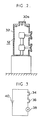
- Fig. 2 is a cross sectional view showing the state in which a photoelectric detector element is installed
- Fig. 3 is a view showing an electrical diagram of the control circuit
- Fig. 4 is a view showing a conventional gas insulated switchgear.
- Fig. 1 illustrates one embodiment of the present invention.
- a voltage transformer 50 is used as a fault detecting means.
- photoelectric detector elements 30a - 30u which are arc detecting means are provided.
- Fig. 2 illustrates the manner in which the photoelectric detector element 30a is mounted to the vessel 32 of the interrupter 12.
- the photoelectric detector element 30a provides an output.
- This output is supplied to a control circuit 10 shown in Fig. 1.
- a simplified circuit diagram of the control circuit 10 is shown in Fig. 3.
- a contact 34 closes.
- the contact 36 is also closed. Therefore, the coil 38 is energized and the interrupters 12, 14 and 16 are tripped open.
- the contact 36 is closed even when a very small arc which does not result in a fault is generated. However, in this case, since an abnormal current is not detected at the voltage transformer 50, the contact 34 is kept open. That is, no unnecessary interrupting operation is effected.
- a photoelectric detector element is used as an arc detecting means in the above embodiment, an element which detects vibration or pressure change generated by the arc may also be used.
- an element for detecting a zero-phase current may be employed as the fault detecting means.
- an occurrence of a fault is detected by a fault detecting means and the determination of whether the fault is outside of the region to be protected or inside of the region to be protected is made by an arc detecting means. Therefore, the following advantages are provided.
Landscapes
- Engineering & Computer Science (AREA)
- Power Engineering (AREA)
- Gas-Insulated Switchgears (AREA)
- Protection Of Static Devices (AREA)
Claims (4)
- Gasisolierte Schaltanlage mit mindestens einem Unterbrecher (12,14,16), der an einem Ende eines zu schützenden Bereiches angeordnet ist, mit einem Fehler-Erkennungsmittel (50) zur Ermittlung eines Fehlers, und mit mindestens einer Lichtbogen-Erkennungsvorrichtung (30), die zur Ermittlung eines Lichtbogens innerhalb eines mit einem elektrisch isolierenden Gas gefüllten Gefässes (32) angeordnet ist, wobei sich dieses Gefäss in dem zu schützenden Bereich befindet, dadurch gekennzeichnet, dass Steuermittel (10) so ausgebildet sind, dass sie den genannten Unterbrecher nur dann betätigen, wenn das genannte Fehler-Erkennungsmittel (50) den Fehler feststellt und die Lichtbogen-Erkennungsvorrichtung (30) den Lichtbogen feststellt.
- Gasisolierte Schaltanlage nach Patentanspruch 1, in der die Lichtbogen-Erkennungsvorrichtung (30) das Licht des Lichtbogens feststellt.
- Gasisolierte Schaltanlage nach Patentanspruch 1, in der die Lichtbogen-Erkennungsvorrichtung (30) die Vibration oder den Druckwechsel, die vom Lichtbogen herrühren, feststellt.
- Gasisolierte Schaltanlage nach Patentanspruch 1, in der eine genannte Lichtbogen-Erkennungsvorrichtung zwischen dem Unterbrecher und dem Fehler-Erkennungsmittel (50) angeordnet ist.
Applications Claiming Priority (2)
| Application Number | Priority Date | Filing Date | Title |
|---|---|---|---|
| JP60073114A JPS61231828A (ja) | 1985-04-04 | 1985-04-04 | ガス絶縁開閉装置 |
| JP73114/85 | 1985-04-04 |
Publications (3)
| Publication Number | Publication Date |
|---|---|
| EP0197778A2 EP0197778A2 (de) | 1986-10-15 |
| EP0197778A3 EP0197778A3 (en) | 1987-09-30 |
| EP0197778B1 true EP0197778B1 (de) | 1991-03-13 |
Family
ID=13508915
Family Applications (1)
| Application Number | Title | Priority Date | Filing Date |
|---|---|---|---|
| EP86302516A Expired EP0197778B1 (de) | 1985-04-04 | 1986-04-04 | Gasisolierte Schaltanlage |
Country Status (5)
| Country | Link |
|---|---|
| US (1) | US4688136A (de) |
| EP (1) | EP0197778B1 (de) |
| JP (1) | JPS61231828A (de) |
| CN (1) | CN86102108B (de) |
| DE (1) | DE3678017D1 (de) |
Families Citing this family (19)
| Publication number | Priority date | Publication date | Assignee | Title |
|---|---|---|---|---|
| US4814834A (en) * | 1984-04-03 | 1989-03-21 | Canon Kabushiki Kaisha | Electrophotographic apparatus |
| JPS61290616A (ja) * | 1985-06-18 | 1986-12-20 | 三菱電機株式会社 | 碍子形ガス遮断器 |
| EP0483121B1 (de) * | 1986-06-06 | 1994-09-07 | Mitsubishi Denki Kabushiki Kaisha | Schaltvorrichtung |
| JPH0767213B2 (ja) * | 1986-09-29 | 1995-07-19 | 三菱電機株式会社 | ガス絶縁開閉装置 |
| JPH0623130Y2 (ja) * | 1986-10-07 | 1994-06-15 | 三菱電機株式会社 | ガス絶縁開閉装置 |
| JPS63121408A (ja) * | 1986-11-11 | 1988-05-25 | 三菱電機株式会社 | 三相一括形ガス絶縁開閉装置 |
| US4839767A (en) * | 1987-02-02 | 1989-06-13 | Mitsubishi Denki Kabushiki Kaisha | Element and device for detecting internal faults in an insulating gas charged electrical apparatus |
| FR2631494B1 (fr) * | 1988-04-18 | 1991-04-19 | Alsthom | Cellule pour poste blinde a moyenne et haute tension et poste constitue de telles cellules |
| US5064998A (en) * | 1988-08-04 | 1991-11-12 | Whirlpool Corporation | Relay control apparatus |
| JP2638255B2 (ja) * | 1990-04-28 | 1997-08-06 | 三菱電機株式会社 | 負荷時タップ切換器監視装置 |
| DE9420199U1 (de) * | 1994-12-07 | 1995-02-09 | Siemens AG, 80333 München | Metallgekapselte Hochspannungsschaltanlage |
| FR2757321B1 (fr) * | 1996-12-16 | 1999-01-15 | Gec Alsthom T & D Sa | Procede de discrimination entre un arc interne et un arc de coupure detectes dans une installation electrique sous enveloppe metallique |
| CN100461573C (zh) * | 2003-12-26 | 2009-02-11 | 西安润辉科技发展有限公司 | 中低电压母线短路保护方法 |
| US10478547B2 (en) | 2012-10-30 | 2019-11-19 | Preva, Llc. | Irrigation assembly |
| US11980352B2 (en) | 2012-10-30 | 2024-05-14 | Preva, Llc | Nasal irrigation diagnostic assembly |
| US11179513B2 (en) | 2012-10-30 | 2021-11-23 | Preva, Llc | Irrigation assembly |
| ITRM20130314A1 (it) | 2013-05-30 | 2014-12-01 | Ist Fisioterap Ospitalroma | Sistema per radioterapia provvisto di un programma per il calcolo della intensità di un fascio di elettroni. |
| KR101491486B1 (ko) * | 2013-10-10 | 2015-02-11 | 현대중공업 주식회사 | 포토 다이오드를 이용한 가스절연 개폐기의 아크 감지 장치 및 방법 |
| US11311706B2 (en) | 2014-02-13 | 2022-04-26 | Preva, Llc | Nasal irrigation assembly and system |
Family Cites Families (14)
| Publication number | Priority date | Publication date | Assignee | Title |
|---|---|---|---|---|
| CH370158A (de) * | 1958-10-29 | 1963-06-30 | Sprecher & Schuh Ag | Vorrichtung zum Schutz vor Lichtbogenwirkungen in einer Starkstromanlage |
| FR1413925A (fr) * | 1964-07-22 | 1965-10-15 | Coq France | Dispositif de protection pour appareil électrique blindé à très haute tension etappareil pourvu d'un tel dispositif |
| DE2248117B2 (de) * | 1972-09-28 | 1975-03-20 | Siemens Ag, 1000 Berlin Und 8000 Muenchen | Überspannungsableiter mit einem gasgefüllten Gehäuse |
| DE2635702A1 (de) * | 1976-08-07 | 1978-02-09 | Bbc Brown Boveri & Cie | Metallgekapselte, druckgasisolierte hochspannungsschaltanlage |
| DE2644422B2 (de) * | 1976-09-30 | 1980-11-20 | Siemens Ag, 1000 Berlin Und 8000 Muenchen | Schutzeinrichtung fur Energieversorgungsnetze im Bergbau unter Tage |
| JPS5465348A (en) * | 1977-11-02 | 1979-05-25 | Kazumi Kai | Photoorelay of detecting trouble of inside of transformer |
| US4275431A (en) * | 1978-02-27 | 1981-06-23 | Westinghouse Electric Corp. | High-voltage single-shot circuit-protecting device with fuse-like characteristics and having a chemical operating mechanism |
| JPS57196824A (en) * | 1981-05-29 | 1982-12-02 | Tokyo Shibaura Electric Co | Secondary arc extinguishing device for power system |
| JPS5869414A (ja) * | 1981-10-16 | 1983-04-25 | 株式会社日立製作所 | ガス絶縁開閉装置 |
| JPS5872325A (ja) * | 1981-10-26 | 1983-04-30 | 株式会社東芝 | ガス絶縁開閉装置における母線事故の保護装置 |
| DE3364632D1 (en) * | 1982-04-05 | 1986-08-28 | Y S Securities Ltd | Electrical switchgear |
| DE3217186A1 (de) * | 1982-05-04 | 1983-11-10 | Siemens AG, 1000 Berlin und 8000 München | Druckgasisolierte hochspannungsschaltanlage mit insbesondere einphasiger metallischer kapselung |
| US4528437A (en) * | 1983-06-28 | 1985-07-09 | General Electric Company | Electrical brazing anti-arcing control circuit |
| US4536814A (en) * | 1984-03-26 | 1985-08-20 | Eaton Corporation | D. C. power controller with fuse protection |
-
1985
- 1985-04-04 JP JP60073114A patent/JPS61231828A/ja active Pending
-
1986
- 1986-03-26 CN CN86102108A patent/CN86102108B/zh not_active Expired
- 1986-04-03 US US06/847,462 patent/US4688136A/en not_active Expired - Fee Related
- 1986-04-04 DE DE8686302516T patent/DE3678017D1/de not_active Expired - Lifetime
- 1986-04-04 EP EP86302516A patent/EP0197778B1/de not_active Expired
Also Published As
| Publication number | Publication date |
|---|---|
| US4688136A (en) | 1987-08-18 |
| EP0197778A3 (en) | 1987-09-30 |
| CN86102108A (zh) | 1986-10-01 |
| DE3678017D1 (de) | 1991-04-18 |
| JPS61231828A (ja) | 1986-10-16 |
| CN86102108B (zh) | 1988-07-06 |
| EP0197778A2 (de) | 1986-10-15 |
Similar Documents
| Publication | Publication Date | Title |
|---|---|---|
| EP0196234B1 (de) | Gasisolierte Schaltanlage | |
| EP0197778A2 (de) | Gasisolierte Schaltanlage | |
| US5886861A (en) | Apparatus providing response to arc faults in a power distribution cable protected by cable limiters | |
| US6141192A (en) | Arcing fault protection system for a switchgear enclosure | |
| US6882257B2 (en) | Earth Leakage Breaker | |
| US11817695B2 (en) | Phase-selective interruption for three-phase AC circuits with Thomson coil actuated switches and breakers | |
| CA2310619C (en) | Arcing fault protection system for a switchgear enclosure | |
| US20220052517A1 (en) | Arc flash detection apparatus and electrical system including the same | |
| JP2527023Y2 (ja) | ガス絶縁開閉装置の事故点標定装置 | |
| EP1318587A2 (de) | Gerät und Verfahren zur Wartung einer Sammelschienenanordnung | |
| JP2644813B2 (ja) | 開閉機器の異常監視装置 | |
| JPH08241654A (ja) | ガス遮断器の故障検出装置 | |
| JPS60180029A (ja) | 真空開閉装置 | |
| JPH0614767B2 (ja) | 光方式地絡検出装置 | |
| CA3071511C (en) | Apparatus and method for arc flash protection in electrical power systems | |
| KR20010013527A (ko) | 사고전류를 억제할 수 있는 직접 접지 시스템 | |
| JPH07227018A (ja) | ガス絶縁開閉装置の故障区画検出装置 | |
| JP2956438B2 (ja) | ガス絶縁開閉装置の故障区画検出装置 | |
| SU465669A1 (ru) | Датчик тока на герконах | |
| JPS63217916A (ja) | 漏電遮断器 | |
| JPH03212103A (ja) | ガス絶縁電器 | |
| JPH08235975A (ja) | ガス遮断器の故障検出装置 | |
| JPH0879965A (ja) | ガス絶縁開閉装置の事故点標定方法 | |
| JPH08163726A (ja) | ガス絶縁開閉装置 | |
| HU205683B (en) | Structural arrangement for short-circuit protection of gas-insulated high-voltage switching apparatuses |
Legal Events
| Date | Code | Title | Description |
|---|---|---|---|
| PUAI | Public reference made under article 153(3) epc to a published international application that has entered the european phase |
Free format text: ORIGINAL CODE: 0009012 |
|
| AK | Designated contracting states |
Kind code of ref document: A2 Designated state(s): CH DE GB LI |
|
| PUAL | Search report despatched |
Free format text: ORIGINAL CODE: 0009013 |
|
| AK | Designated contracting states |
Kind code of ref document: A3 Designated state(s): CH DE GB LI |
|
| 17P | Request for examination filed |
Effective date: 19880129 |
|
| 17Q | First examination report despatched |
Effective date: 19900103 |
|
| GRAA | (expected) grant |
Free format text: ORIGINAL CODE: 0009210 |
|
| AK | Designated contracting states |
Kind code of ref document: B1 Designated state(s): CH DE GB LI |
|
| REF | Corresponds to: |
Ref document number: 3678017 Country of ref document: DE Date of ref document: 19910418 |
|
| REG | Reference to a national code |
Ref country code: GB Ref legal event code: 727 |
|
| REG | Reference to a national code |
Ref country code: GB Ref legal event code: 727A |
|
| REG | Reference to a national code |
Ref country code: GB Ref legal event code: 727B |
|
| REG | Reference to a national code |
Ref country code: GB Ref legal event code: SP |
|
| PLBE | No opposition filed within time limit |
Free format text: ORIGINAL CODE: 0009261 |
|
| STAA | Information on the status of an ep patent application or granted ep patent |
Free format text: STATUS: NO OPPOSITION FILED WITHIN TIME LIMIT |
|
| 26N | No opposition filed | ||
| PGFP | Annual fee paid to national office [announced via postgrant information from national office to epo] |
Ref country code: GB Payment date: 19930405 Year of fee payment: 8 |
|
| PGFP | Annual fee paid to national office [announced via postgrant information from national office to epo] |
Ref country code: CH Payment date: 19930427 Year of fee payment: 8 |
|
| PGFP | Annual fee paid to national office [announced via postgrant information from national office to epo] |
Ref country code: DE Payment date: 19930506 Year of fee payment: 8 |
|
| PG25 | Lapsed in a contracting state [announced via postgrant information from national office to epo] |
Ref country code: GB Effective date: 19940404 |
|
| PG25 | Lapsed in a contracting state [announced via postgrant information from national office to epo] |
Ref country code: LI Effective date: 19940430 Ref country code: CH Effective date: 19940430 |
|
| GBPC | Gb: european patent ceased through non-payment of renewal fee |
Effective date: 19940404 |
|
| REG | Reference to a national code |
Ref country code: CH Ref legal event code: PL |
|
| PG25 | Lapsed in a contracting state [announced via postgrant information from national office to epo] |
Ref country code: DE Effective date: 19950103 |