EP0197705B1 - Infusionspumpe mit verfügbarer Kassette - Google Patents
Infusionspumpe mit verfügbarer Kassette Download PDFInfo
- Publication number
- EP0197705B1 EP0197705B1 EP86302220A EP86302220A EP0197705B1 EP 0197705 B1 EP0197705 B1 EP 0197705B1 EP 86302220 A EP86302220 A EP 86302220A EP 86302220 A EP86302220 A EP 86302220A EP 0197705 B1 EP0197705 B1 EP 0197705B1
- Authority
- EP
- European Patent Office
- Prior art keywords
- pump
- chamber
- pumping
- pressure
- fluid
- Prior art date
- Legal status (The legal status is an assumption and is not a legal conclusion. Google has not performed a legal analysis and makes no representation as to the accuracy of the status listed.)
- Expired
Links
- 238000001802 infusion Methods 0.000 title claims description 19
- 238000005086 pumping Methods 0.000 claims description 61
- 239000012530 fluid Substances 0.000 claims description 59
- 238000012546 transfer Methods 0.000 claims description 21
- 230000004913 activation Effects 0.000 claims description 5
- 230000007423 decrease Effects 0.000 claims description 5
- 230000003213 activating effect Effects 0.000 claims description 4
- 238000007911 parenteral administration Methods 0.000 claims description 4
- 230000001419 dependent effect Effects 0.000 claims description 3
- 239000002985 plastic film Substances 0.000 claims description 3
- 238000011144 upstream manufacturing Methods 0.000 claims description 3
- XLYOFNOQVPJJNP-UHFFFAOYSA-N water Substances O XLYOFNOQVPJJNP-UHFFFAOYSA-N 0.000 claims description 3
- 230000007547 defect Effects 0.000 claims description 2
- 229920002457 flexible plastic Polymers 0.000 claims description 2
- 238000001514 detection method Methods 0.000 claims 7
- 230000005484 gravity Effects 0.000 description 5
- 239000000463 material Substances 0.000 description 3
- 238000012544 monitoring process Methods 0.000 description 3
- 230000000694 effects Effects 0.000 description 2
- 238000001990 intravenous administration Methods 0.000 description 2
- 239000002184 metal Substances 0.000 description 2
- 230000002572 peristaltic effect Effects 0.000 description 2
- 230000000717 retained effect Effects 0.000 description 2
- 238000005096 rolling process Methods 0.000 description 2
- 238000013459 approach Methods 0.000 description 1
- 238000010276 construction Methods 0.000 description 1
- 239000003814 drug Substances 0.000 description 1
- 229940079593 drug Drugs 0.000 description 1
- 230000012447 hatching Effects 0.000 description 1
- 238000001361 intraarterial administration Methods 0.000 description 1
- 238000004519 manufacturing process Methods 0.000 description 1
- 238000000034 method Methods 0.000 description 1
- 230000000474 nursing effect Effects 0.000 description 1
- 229920000915 polyvinyl chloride Polymers 0.000 description 1
- 239000004800 polyvinyl chloride Substances 0.000 description 1
- 238000003825 pressing Methods 0.000 description 1
- 239000002904 solvent Substances 0.000 description 1
- 238000003860 storage Methods 0.000 description 1
- 238000007666 vacuum forming Methods 0.000 description 1
Images


Classifications
-
- A—HUMAN NECESSITIES
- A61—MEDICAL OR VETERINARY SCIENCE; HYGIENE
- A61M—DEVICES FOR INTRODUCING MEDIA INTO, OR ONTO, THE BODY; DEVICES FOR TRANSDUCING BODY MEDIA OR FOR TAKING MEDIA FROM THE BODY; DEVICES FOR PRODUCING OR ENDING SLEEP OR STUPOR
- A61M5/00—Devices for bringing media into the body in a subcutaneous, intra-vascular or intramuscular way; Accessories therefor, e.g. filling or cleaning devices, arm-rests
- A61M5/14—Infusion devices, e.g. infusing by gravity; Blood infusion; Accessories therefor
- A61M5/142—Pressure infusion, e.g. using pumps
- A61M5/14212—Pumping with an aspiration and an expulsion action
- A61M5/14224—Diaphragm type
-
- A—HUMAN NECESSITIES
- A61—MEDICAL OR VETERINARY SCIENCE; HYGIENE
- A61M—DEVICES FOR INTRODUCING MEDIA INTO, OR ONTO, THE BODY; DEVICES FOR TRANSDUCING BODY MEDIA OR FOR TAKING MEDIA FROM THE BODY; DEVICES FOR PRODUCING OR ENDING SLEEP OR STUPOR
- A61M2205/00—General characteristics of the apparatus
- A61M2205/12—General characteristics of the apparatus with interchangeable cassettes forming partially or totally the fluid circuit
- A61M2205/128—General characteristics of the apparatus with interchangeable cassettes forming partially or totally the fluid circuit with incorporated valves
Definitions
- This invention relates to the delivery of a fluid to a patient by pressurizing the fluid, and in particular to delivery by an infusion pump which incorporates on inexpensive disposable cassette.
- Infusion of fluids, such as drugs and plasma, into a patient is commonplace in the medical field.
- Two common infusion methods are intravenous delivery of fluids by gravity and either intravenous or intraarterial delivery by actually pumping the fluids for delivery to the patient.
- an infusion pump In pump delivery, an infusion pump is used to pressurize the fluid. Past devices often require a complex cassette mechanism which comes into direct contact with the fluid to be delivered.
- peristaltic pumps acting upon in-line tubing segments have been used in this art.
- One example of a peristaltic pump, disclosed in U.S. Patent 4,155,362 includes a back pressure valve to prevent gravity siphoning from the pumping chamber.
- U.S. Patent 4,142,524 Another relatively simple pumping arrangement is disclosed in U.S. Patent 4,142,524, in which a casette is provided with inlet and outlet valves to and from a pumping chamber. The pump presses a rubber diaphragm on the cassette to diminish the volume of the casette chamber by a known amount to deliver a predetermined quantity per pump stroke.
- An even simpler disposable element is disclosed in the pumping arrangement of U.S. Patent 4,199,307, in which a pancake-shaped resilient pumping chamber is provided with upper and lower valves and an activating pumping piston which displaces a known volume on the pumping stroke.
- Yet another pump approach is disclosed in U.S.
- Patent 4,322,201 which seeks to provide continuous, uninterrupted fluid flow by alternating between two pumping chambers, each of which employs the principle of the rolling diaphragm.
- a third rolling diaphragm chamber is employed for mechanically sensing pressure within the device for control purposes.
- US-A-4276004 shows a pump for parenteral administration of fluid to a patient at a selectable rate comprising: a flexible cassette defining a flow path between an inlet and an outlet, and a pump chamber located in the flow path; an instrument body having a compartment receiving the cassette and confining the pump chamber; pumping means associated with the instrument body adjacent the compartment for confining the pump chamber, the pumping means comprising a movable hub circumferentially surrounded by radially extending petal-haped sections, each of which is pivotally mounted to the hub at its inner end and to a portion of the instrument body at its outer end; and activation means provided for activating the pumping means to cause the hub and petal-shaped sections to undergo relative rotation.
- the present invention is characterised in that the cassette is formed by the joinder of two flexible plastic sheets, in that said hub and petal-shaped sections defining a surface for contacting the outer surface of one flexible sheet and for urging the sheet toward the other flexible sheet to decrease the volume of the pumping chamber and pressurise the fluid therein, and in that said activation means causes the hub and petal-shaped sections to move into the compartment to reduce the volume of the pump chamber at a rate dependent upon the selected rate.
- US-A-4236880 discloses a disposable cassette, for use with a parenteral administration pump body, the disposable cassette comprising: a first flexible and substantially flat sheet; a second flexible and substantially flat sheet bonded to the first sheet; a narrow inlet passage formed between the sheets by bonding of the first and second sheets along spaced parallel lines; a narrow outlet passage formed between the sheets by bonding of the first and second sheets along spaced parallel lines; and a pump chamber between the sheets communicating with the inlet and outlet.
- a disposable cassette of the aforementioned type characterised in that the pump chamber is capable of distension from its normally flat state by introduction of fluid at a pressure of ten inches (25.4 cm) of water through the inlet into the pump chamber whilst the outlet is closed.
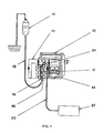
- the pumping system is composed of an instrucment 10 in which a disposable cassette 12 is mounted for operation.
- Supply container 14 containing the fluid to be infused is connected to inlet 16 of the cassett 12 by means of tubing 18.
- Outlet tubing 20 extends to the patient 22 from the outlet 24 of cassette 12.
- Cassette 12 is formed by a first flexible sheet 26 and a second flexible sheet 28, which may be formed from a suitable flexible sheet material, such a polyvinyl chloride.
- the cassette 12 may be assembled by bonding sheets 26 and 28 over a selected bonding area 30 indicated by hatching in FIGURE 4.
- the bonding area 30 includes bonding along spaced parallel lines 32 in order to form a cassette inlet passage 16 extending from one end of the cassette between sheets 26 and 28.
- Inlet passage 16 extends to a supply chamber 34 having a generally circular configuration.
- a transfer passage 36 extends from the side of supply chamber 34 opposite inlet passage 16, communicating with a pump chamber 38 Bonding along two parallel lines 40, extending from pump chamber 38 forms outlet passage 24.
- cassette 12 there is provided longitudinally through the central area of cassette 12, a continuous fluid path extending from inlet 16 through supply chamber 34, transfer passage 36, and pump chamber 38 to the cassette outlet 24.
- Supply tube 18 is inserted into inlet passage 16 and bonded by any suitable means, such as by solvent bonding.
- patient tube 20 is inserted into outlet passage 24 and bonded thereto.
- the cassette is, as shown in FIGURE 5, essentially flat. This permits production of the cassette from flat sheet without the necessity of any forming operation.
- the flexibility of the cassette must be sufficient that, with fluid at a relatively low pressure being provided at the inlet 16, with the outlet 24 closed, fluid will flow into the cassette filling it and causing the chamber 34 and 38 to bulge with fluid by stretching of the sheets 26 and 28.
- Four mounting holes 42 are provided in the margins of the cassette for positioning and mounting of the cassette in the instrument 10.
- the front panel of the instrument body is functionally divided into a data display/operator input panel 44 and a cassette receiving and actuating section 46, which is concealed behind one or more doors (not shown in FIGURE 1).
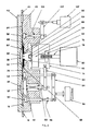
- the details of construction of the cassette receiver/actuator section 46 are best illustrated in FIGURES 2 and 3.
- the moving members which operate upon cassette 12 when it is in operating position are arrayed on panel 48 secured to the instrument body. Proceding from upstream, the major elements are: inlet valve 50, refill pressure member 52, transfer valve 54, petal assembly pumping member 56, and delivery valve 58.
- Petal assembly 56 includes a central hub 60 surrounded by a plurality of petal shaped sections 62 to form the movable pressing surface which produces pumping pressure in the device.
- the hub 60 is formed by press fit of male hub member 60a and female hub member 60b.
- a circular recess 64 near the outer edge of hub 60 is formed between the two hub members.
- Each petal section 62 is provided on the rear face of its inner end with a smooth hooked-shape curve portion 66 which corresponds to a smooth curve provided on the hub recess 64.
- each petal section 62 is pivotally retained in the hub recess 64, with the complimentary smooth curves of each member permitting relative pivotal movement of each petal shaped section with respect to the hub about an axis adjacent recess 64.
- the instrument body panel 48 is provided with an annular petal nest 68 that circumferentially surrounds hub 60 and retains the outer end of each petal shaped section 62.
- the confronting surfaces of petal nest recess 68 and the outer end of each petal shaped section 62 are also shaped for smooth pivoting of the petal shaped sections with respect to the instrument body about an axis adjacent the nest 68.
- a movable carriage 74 is mounted behind hub 60, and carries a drive nut 76 which is engaged with the threads of a threaded motor shaft 78 rotated by stepper motor 80.
- the forward end of carriage 74 is recessed to receive a load cell 82.
- Load cell 82 has its central force-measuring diaphragm confronting a metal ball 84 retained in a rear central recess 86 formed on hub 60.
- stepper motor 80 acts, through the cooperation of threaded motor shaft 78 and carriage nut 76 to drive carriage 74 forward. This action transmits force through load cell 82 and metal ball 84 to hub 60, moving the hub forward.
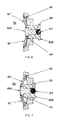
- the translational motion of hub 60 also causes each petal shaped section 62 to pivot near each of its ends.
- the petal assembly thus forms a truncated cone of varying height as the hub moves between the extreme positions illustrated in FIGURES 6 and 7.
- Refill pressure member 52 is carried at the forward end of refill shaft 88, which is driven either forwardly or rearwardly through lever 90 acted upon by the carriage 74.
- the action of refill lever 90 causes shaft 88 and refill pressure member 52 to be withdrawn.
- lever 90 allows the refill pressure member 52 to move forward.
- Spring 92 biases refill pressure member 52 to its forward position, and thus carriage 74 to the rearward direction.
- Inlet valve 50 and transfer valve 54 have rounded surfaces for engaging the flow path of the cassette, and are operated in tandem fashion through inlet valve lever 94 driven by solenoid 96.
- inlet valve lever 94 driven by solenoid 96.
- the parts are assembled so that in the middle of the path of travel of valve lever 94, both valves are closed to ensure no by-passing of fluid.
- Bias to inlet valve lever 94 is provided by spring 98 surrounding the inlet valve shaft, which biases the arrangement to the condition of inlet valve open, transfer valve closed.
- Delivery valve 58 is operated by a stepper motor 102 acting through delivery valve lever 104, and is biased to the closed position by spring 106.
- the linear stepper motor 102 is capable of positioning the delivery restriction valve 58 in any position from fully retracted or open position, as shown, to a fully extended or closed position.
- Actuator panel 48 is provided with mounting pins 108 corresponding to the mounting holes 42 in cassette 12.
- An actuator door 110 is mounted to panel 48 by hinges 112 and is closed by latch 113.
- a second outer door 111 (FIGURE 1) is preferably used to enclose door 110. As a double check for patient safety, opening of this outer door 111 would stop pumping and sound an alarm.
- concave depression 114 is arranged to confront petal assembly 56 when the door is closed, and similar concave depression 116 confronts the refill pressure member 52. Depressions 114 and 116 are provided with air vent holes through the front of the door to facilitate closing of the door with the cassette 12 in position.
- the pump chamber 38 of the cassette is captured between petal assembly 56 and door depression 114.
- the supply chamber 34 is likewise captured between pressure member 52 and door depression 116.
- valve 50 is adjacent inlet passage 16 to close off the inlet when valve member 50 is extended.
- valve 54 may be activated to close off transfer passage 36.
- the delivery valve 50 may be activated to selectively close outlet 24 of cassette 12, to an orifice of any desired size.
- the pumping compartment defined between the rigid wall of depression 114 and the petal assembly 56 must be completely filled by the fluid filled pump chamber 38 when the petal assembly 56 is in its retracted position illustrated in FIGURE 6, and the pump chamber 38 is bulged with fluid at a low fluid pressure of approximately 10 inches of water.
- the volumetricity of pumping is then provided by the accuracy of volume displaced between the extreme positions of the petal assembly 56 illustrated in FIGURES 6 and 7, and the compliance of sheet 28 to the moving truncated cone surface presented by the petal assembly 56.
- the material used to construct the cassette is flexible it conforms to the surface of the petal elements so that the position of the petal assembly defines the volume of fluid enclosed between it and the hemispherical surface on the other side very precisely. This enables the volumetric performance of this arrangement to be defined almost completely by the movement of the hub, and thus of the petal shaped sections, and not by the mechanical properties of the disposable element.
- the volume displaced by the petal assembly varies in a linear fashion with the translational movement of hub 60.
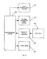
- microprocessor 120 controls the movement of solenoid 96 between its two positions: (1) inlet valve open, transfer valve closed, and (2) inlet valve closed, transfer valve open.
- microprocessor 120 controls delivery valve stepper motor 102 to select the total or partial restriction imposed by delivery valve 58 on the cassette outlet 24.
- Microprocessor 120 also selects, in accordance with the rate selected by the operator on input panel 44, the rate of movement of the pumping stepper motor 80. Continuous control over operation, and diagnostics for abberant conditions, are principally provided by load cell 82 which directly measures the force being exerted on the pump chamber 38 by petal assembly 56. This data is continuously provided to microprocessor 120 through A/D converter 122.
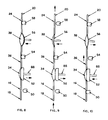
- FIGURE 8 illustrates the condition of the actuator and disposable as the delivery portion of the cycle has begun.
- the pump chamber 38 has been completely filled with fluid to occupy the compartment with petal assembly 56 fully retracted.
- Delivery valve 58 and transfer valve 54 are closed, completely capturing the fluid in pump chamber 38.
- Inlet value 50 is opened, so that fluid may enter the supply chamber 34 as refill pressure member 52 is retracted.
- the microprocessor begins the initial stage of the delivery cycle by directing the pump chamber stepper motor 80 to advance to begin pressurization of the fluid in pump chamber 38.
- valves 58 and 54 remain closed to permit this initial pressurization.
- Elevation of the force required to advance the petal assembly 56 is sensed by load cell 82 which data is fed to the microprocessor 120.
- This state serves as a diagnostic to verity the capturing of a full load of fluid in the pump chamber 38.
- a failure to pressurize in the first several steps of motor 80 indicates a system problem. It could be that the fluid supply is depleted, so that the pump chamber 38 has not been filled, or that the supply container 14 is at an inadequate height to cause the gravity fill into inlet 16 of the cassette.
- a third possibility is that a valve defect in valve 54 or 58 is permitting fluid to leak from the chamber 38. In any of these events, operation of the instrument will be stopped by the microprocessor 120 and an alarm sounded.
- microprocessor 120 instructs delivery valve 58 to open as motor 80 advances, to deliver fluid to the patient through outlet 24, as illustrated in FIGURE 9.
- Continuous monitoring of load cell 82 permits the microprocessor to exercise continuous control over delivery valve 58 to selectively restrict the outlet 24. This permits the device to ensure that gravity siphoning at a higher rate than the requested rate does not occur.
- the microprocessor is also programmed with a selected maximum pressure limit set by the user through display/input panel 44, which is used in the continuous pressure monitoring. Escalation of pressure above the selected maximum pressure, even with the delivery valve 58 wide open, will result in alarm and shutdown of the instrument, indicating that there is some occlusion which requires nursing attention, and that fluid is not reaching the patient. The ability to select a maximum pressure limit by the user permits relatively rapid occlusion alarms, even at relatively low selected infusion rates.
- the microprocessor is programmed to maintain a relatively constant pressure in pump chamber 38 by selective restriction of delivery valve 58, such constant pressure being just below the maximum pumping pressure selected by the operator. This is helpful in ensuring that there are no variations in volumetric delivery which might result from operation at varying pumping pressures.
- valves 50 and 58 close, and valve 54 opens.
- Microprocessor 120 then reverses stepper motor 80 for a rapid retraction of petal assembly 56 and a rapid extension of refill pressure member 52 as illustrated in FIGURE 10. This permits a very quick transfer of fluid into pump chamber 38 which will arm the device for the next delivery cycle.
- energy was stored in the spring 92 immediately behind the refill pressure member 52. This energy is used to effect the transfer of fluid so as to drastically reduce the mechanical loading on the main pump motor.
- valve 50 opens and valve 54 closes and the system is in the condition once more indicated in FIGURE 8.
- a mechanical stop on shaft 88 limits the amount of movement of the refill piston 52 so as to avoid pumping any fluid back towards the fluid container 14 as valve 50 opens.
- cassette and instrument could be designed without supply chamber 34, refill pressure member 52, and transfer valve 54, but in that event the refill cycle time would be dependent upon the rate of flow into pump chamber 38 dictated by natural forces of gravity.
- Use of the device in the form illustrated permits the instrument to control the time taken up by the refilling of pump chamber 38, and to cause that step to happen rapidly to limit the duration of the refilling cycle.
Landscapes
- Health & Medical Sciences (AREA)
- Vascular Medicine (AREA)
- Engineering & Computer Science (AREA)
- Anesthesiology (AREA)
- Biomedical Technology (AREA)
- Heart & Thoracic Surgery (AREA)
- Hematology (AREA)
- Life Sciences & Earth Sciences (AREA)
- Animal Behavior & Ethology (AREA)
- General Health & Medical Sciences (AREA)
- Public Health (AREA)
- Veterinary Medicine (AREA)
- Infusion, Injection, And Reservoir Apparatuses (AREA)
- External Artificial Organs (AREA)
Claims (19)
- Pumpe zur parenteralen Verabreichung eines Fluids an einen Patienten mit einer wählbaren Geschwindigkeit, mit:
einer flexiblen Kassette (12), die einen Flußpfad zwischen einem Einlaß (16) und einem Auslaß (24) definiert, und einer in dem Flußpfad angeordneten Pumpenkammer (38);
einem Instrumentenkörper (10), der eine Abteilung (46) aufweist, die die Kassette (12) aufnimmt und die Pumpenkammer (38) begrenzt;
einer Pumpeinrichtung, die mit dem Instrumentenkörper neben der Abteilung (46) verbunden ist, um die Pumpenkammer (38) zu begrenzen, wobei die Pumpeinrichtung einen beweglichen Stempel (60) aufweist, der an seinem Umfang durch sich radial erstreckende speichenförmige Abschnitte (62) umgeben ist, von denen jeder mit seinem inneren Ende (66) an dem Stempel (60) und mit seinem äußeren Ende (68) an einem Teil des Instrumentenkörpers schwenkbar angebracht ist; und einer Aktivierungseinrichtung, die zum Aktivieren der Pumpeneinrichtung vorgesehen ist, um den Stempel (60) und die speichenförmigen Abschnitte (62) zu veranlassen, eine relative Drehung durchzufuhren, dadurch gekennzeichnet, daß die Kassette (12) durch die Verbindung von zwei flexiblen Plastikblättern (26, 28) gebildet ist, daß der Stempel (60) und die speichenförmigen Abschnitte eine Oberfläche definieren zum Kontaktieren der Außenfläche eines flexiblen Blatts (28) und zum Drücken des Blattes (28) gegen das äußere flexible Blatt (26), um das Volumen der Pumpkammer (38) zu verringern und das Fluid darin unter Druck zu setzen, und daß die Aktivierungseinrichtung den Stempel und die speichenförmigen Abschnitte veranlaßt, sich in die Abteilung zu bewegen, um das Volumen der Pumpenkammer (38) mit einer Geschwindigkeit zu vermindern, die von der gewählten Geschwindigkeit abhängt. - Pumpe nach Anspruch 1, dadurch gekennzeichnet, daß die Kassette ein disponierbares Element (12) ist, das gänzlich aus der Verbindung von zwei im wesentlichen flachen Plastikblättern (26, 28) gebildet ist, einem Zuführrohr (18) das an den Kassetteneinlaß (16) gebunden ist, und einem Patientenrohr (20), das an den Kassettenauslaß (24) gebunden ist.
- Pumpe nach Anspruch 2, dadurch gekennzeichnet, daß die Pumpenkammer (38) durch Verbinden der zwei Blätter (26, 28) um eine ungebundene kreisförmige Fläche herum gebildet ist und der Flußpfad zwischen der Pumpenkammer (38) und dem Einlaß (16) und Auslaß (24) durch Verbinden der Blätter (26, 28) längs zweier beabstandeter paralleler Linien gebildet ist, die sich von der kreisförmigen Fläche aus erstrecken.
- Pumpe nach Anspruch 1, gekennzeichnet durch eine Zuführkammer (34) in dem Flußpfad der Kassette zwischen dem Einlaß (16) und der Pumpenkammer (38), einer Auffüll-Druckeinrichtung (52), die durch den Instrumentenkörper zur Bewegung hin auf und weg von der Zuführkammer (34) getragen wird;
einem Einlaßventil (50), das durch den Instrumentenkörper neben dem Einlaß des disponierbaren Elementes getragen wird;
einem Übertragsventil (54), das durch den Instrumentenkörper neben dem Flußpfad zwischen der Zuführkammer (34) und der Pumpkammer (38) getragen wird; einem Abgabeventil (58), das durch den Instrumentenkörper neben dem Auslaß (24) getragen wird;
und
einer Steuereinrichtung (120), um zu ersten Zeiten das Abgabeventil (58) und das Einlaßventil (50) zu schließen, und das Übertragsventil (54) zu öffnen, und schnell die Pumpeinrichtung (60) von der Pumpkammer (38) zurückzuziehen, während die Auffüll-Druckeinrichtung (52) schnell zu der Zuführkammer (34) hin geschoben wird, wodurch die Pumpkammer (38) schnell gefüllt wird; und zu zweiten Zeiten das Abgabeventil (58) und Einlaßventil (50) zu öffnen und das Übertragsventil (54) zu schließen und die Pumpeinrichtung (80) zu aktivieren, um das Volumen der Pumpkammer (38) mit einer durch die gewählte Abgabegeschwindigkeit bestimmten Geschwindigkeit zu vermindern, während die Auffüll-Druckeinrichtung (52) zurückgezogen wird. - Pumpe nach Anspruch 4, gekennzeichnet durch eine Druck-Erfassungseinrichtung (82), die mit der Pumpeinrichtung (80) verbunden ist, um direkt die Kraft zu messen, die durch die Pumpeinrichtung (80) auf die Pumpkammer (38) ausgeübt wird.
- Pumpe nach Anspruch 5, dadurch gekennzeichnet, daß die Druck-Erfassungseinrichtung (82) eine Meßzelle bzw. Wägedose ist, die wirksam zwischen dem Stempel (60) und der Aktivierungseinrichtung (80) geschaltet ist.
- Pumpe nach Anspruch 5, dadurch gekennzeichnet, daß eine Einrichtung (120) auf die von der Druck-Erfassungseinrichtung (82) getätigte Erfassung eines Druckverlustes in der Pumpenkammer (38) anspricht, um zu veranlassen, daß das Abgabeventil (50) schließt und der Druck in der Pumpkammer (38) steigt und eine Schwerkraftentleerung des Fluids aus der Pumpkammer (38) verhindert ist.
- Pumpe nach Anspruch 5, dadurch gekennzeichnet, daß die Steuereinrichtung (102) zu dritten Zeiten das Abgabeventil (58) und das Übertragsventil (54) veranlaßt zu schließen und das Pumpelement (60), in der Pumpenkammer (38) vorzurücken, und daß eine Alarmeinrichtung vorgesehen ist, um den Betrieb der Pumpe in dem Falle abzuschalten, daß die Druck-Erfassungseinrichtung keinen Druck-Aufbau anzeigt bzw. dient, was einen Verlust an Fluid, das in der Pumpkammer gehalten ist, anzeigt.
- Pumpe nach Anspruch 5, gekennzeichnet durch eine Einschluß-Abschalteinrichtung, um die Pumpe abzuschalten, wenn die Druck-Erfassungseinrichtung (82) erfaßt, daß der Druck in der Pumpenkammer (38) einen vorgewählten maximalen Pumpendruck übersteigt.
- Pumpe nach Anspruch 9, gekennzeichnet durch eine Einrichtung, die auf die Druck-Erfassungseinrichtung (82) anspricht, um den Verschluß des Abgabeventils (58) während der Abgabe einzustellen, um einen konstanten Druck in der Pumpenkammer aufrechtzuerhalten.
- Pumpe nach Anspruch 3, gekennzeichnet durch eine Einrichtung zum Begrenzen der Bewegung der Außenfläche eines ersten Blattes (26); und
eine Einrichtung zum Drücken des Stempelabschnitts (60) des Pumpenelementes zu dem ersten Blatt hin, so daS die speichenförmigen Abschnitte (62) schwenken, wobei die Mittel-Stempelabschnitte (60) und die speichenförmigen Abschnitte (62) gegen das zweite Blatt (28) über im wesentlichen die gesamte Oberfläche des zweiten Blattes neben dem Pumpenelement gedrückt werden, um das Volumen der Pumpkammer zu verringern und Fluid von dort zu pumpen. - Infusionspumpe nach Anspruch 11, dadurch gekennzeichnet, daß die Begrenzungseinrichtung eine konkav gekrümmte Oberfläche von konstantem Radius aufweist, gegen die die Außenseite des ersten Blattes begrenzt ist.
- Infusionspumpe nach Anspruch 11, gekennzeichnet durch ein Einlaßventil (50), das zwischen einer ersten und einer zweiten Position betriebsbereit ist, um den Einlaßdurchgang (16) zu schließen, während es in der ersten Position dazu dient, einen Fluidfluß in die Pumpkammer (38) zu verhindern und den Einlaßdurchgang zu öffnen, um zu ermöglichen, daß Fluid in die Pumpkammer in der zweiten Position fließt; und
ein Abgabeventil (58) zum Öffnen und Schließen des Auslaßdurchgangs (24), so daß sich das Abgabeventil öffnet, um zu ermöglichen, daß Fluid von der Pumpkammer durch das Abgabeventil zu dem Patienten fließt, wenn die Bewegung der Pumpe das Fluid mit einem vorbestimmten Pumpdruck beaufschlagt. - Infusionspumpe nach Anspruch 11, dadurch gekennzeichnet, daß die disponierbare Kassette (12) ferner eine Zuführkammer (34) aufweist, die zwischen zwei Blättern (26, 28) aufwärts von der Pumpkammer (38) definiert ist, wobei der Einlaßdurchgang (16) die Zuführkammer (34) erreicht, wobei die disponierbare Kassette (12) ferner einen Mitteldurchgang (36) aufweist, der die Zuführkammer (34) und Pumpkammer (38) verbindet.
- Infusionspumpe nach Anspruch 13, dadurch gekennzeichnet, daß die Infusionspumpe ferner eine Einrichtung (82) zum Messen des Fluiddrucks in der Pumpkammer (38) aufweist, wobei das Auslaßventil (58) eine elektronische Steuerung (102) aufweist, die auf den von der Druck-Meßeinrichtung (82) gemessenen Fluiddruck anspricht, um die Öffnung des Auslaßventils (58) zu steuern, um die Pumpkammer (38) mit einem vorgewählten Pumpdruck zu beaufschlagen.
- Infusionspumpe nach Anspruch 13, dadurch gekennzeichnet, daß die Druck-Meßeinrichtung (82) ferner einen Einschluß durch Messen des Ansteigens des Fluiddrucks in der Pumpkammer über einen vorbestimmten maximalen Pumpdruck mißt, wenn die Pumpe das Volumen der Pumpkammer vermindert.
- Infusionspumpe nach Anspruch 16, dadurch gekennzeichnet, daß der vorbestimmte maximale Pumpdruck variabel ist, wobei bei geringen Flußgeschwindigkeiten ein verminderter vorbestimmter Pumpdruck verwendet werden kann, um eine Schnellmessung eines Einschlusses zu ermöglichen.
- Pumpe nach Anspruch 1, dadurch gekennzeichnet, daß die Kassette (12) disponierbar ist und eine Zuführkammer (34) aufweist, die zwischen den zwei Blättern (26, 28) aufwärts von der Pumpkammer (38) definiert ist, wobei der Einlaßdurchgang (16) die Zuführkammer (34) erreicht, wobei die disponierbare Kassette (12) ferner einen Mitteldurchgang (36) aufweist, der die Zuführkammer (34) und die Pumpkammer (38) verbindet;
einen Rahmen (110) zum Tragen der disponierbaren Kassette mit einer ersten Oberfläche zum Begrenzen der Bewegung des ersten Blattes (26), wobei die Oberfläche das erste Blatt mit einer im allgemeinen konkaven Form mit konstantem Radius begrenzt;
wobei der bewegliche Stempel (60) und die speichenförmigen Abschnitte der Pumpeinrichtung eine Oberfläche definieren zum Kontaktieren der Außenfläche des zweiten Blattes (28) und zum Drücken des zweiten Blattes (28) zu der ersten Oberfläche hin, um das Volumen der Pumpkammer zu verringern und das Fluid darin unter Druck zu setzen;
eine Kolbenachse (74), die mit dem beweglichen Stempel (60) zusammenwirkt zu einer linearen Bewegung in einer ersten Richtung, um den beweglichen Stempel (60) und die speichenförmigen Abschnitte (62) gegen das zweite Blatt (28) zu drücken;
eine Meßzelle (82), die an der Kolbenachse angebracht ist, um die durch die Kolbenachse (74) auf den Stempel (60) ausgeübte Kraft zu messen;
einen Schrittmotor (80) der mit der Kolbenachse (74) durch die Meßzelle (82) verbunden ist, um eine Kraft auf die Kolbenachse auszuüben,
ein Abgabeventil (58) zum Verändern des Querschnitts des Auslaßdurchgangs (24) zwischen dem Verschluß des Durchgangs und dem offenen unverformten Querschnitt des Auslaßdurchgangs;
einer Einrichtung zum Betreiben des Abgabeventils (58) in Reaktion auf die Kraft, die auf den Mittelabschnitt durch die Kolbenachse ausgeübt ist, welche durch die Meßzelle (82) gemessen wird, um zu veranlassen, daß das Fluid von der Druckkammer in einem vorbestimmten Pumpendruck abgepumpt wird;
ein Übertragsventil (54) zum Schließen und Öffnen des Mitteldurchgangs (36) zwischen der Zuführkammer (34) und der Pumpenkammer (38);
ein Einlaßventil (50) zum Öffnen und Schließen des Einlaßdurchgangs (16) zu der Zuführkammer (34); und eine Mikroprozessor (102)-gesteuerte Einrichtung zum elektronischen Veranlassen des Schrittmotors (80), die Kolbenanordnung (74) in der ersten Richtung zu bewegen, wobei das Mittelventil (154) und Ausgangs-Begrenzungsventil (158) die Mittel-(36) und Auslaß (24) -Durchgänge schließen, um einen Alarm zu erzeugen, wenn der Fluiddruck in der Pumpenkammer nicht innerhalb einer vorbestimmten Bewegung ansteigt, um ein defektes Instrument anzuzeigen, wobei die Mikroprozessor-(102) gesteuerte Einrichtung bei Messung eines Anstieg des Fluiddrucks fortfährt, den Schrittmotor (80) so auszurichten, daß sich die Kolbenanordnung (74) in der ersten Richtung bewegt und die Einrichtung zum Betreiben des Abgabeventils (58) gesteuert wird, um Fluid von der Pumpenkammer (38) mit einem vorbestimmten Pumpendruck zu dem Patienten zu pumpen, wobei das Übertragsventil (54) geschlossen ist und gleichzeitig der Einlaßdurchgang (16) offengehalten wird, um zu ermöglichen, daß Fluid von der Quelle in die Zuführkammer (34) abfließt, wobei die Steuereinrichtung die Geschwindigkeit des von der Infusionspumpe gepumpten Fluids steuert, und zwar durch Steuern der Geschwindigkeit des Schrittmotors (80), um eine vorbestimmte Geschwindigkeit zu haben, bis ein vorbestimmtes Volumen von der Pumpkammer (38) gepumpt wurde, wobei die Steuereinrichtung nachfolgend die Auslaß- (24) und Einlaß (16) -Durchgänge mit dem Auslaß-Begrenzungsventil (58) und Einlaßventil (50) verschließt, während der Mitteldurchgang (36) geöffnet ist und die Kolbenanordnung (74) sich in einer Richtung entgegengesetzt der ersten Richtung so bewegt, daß Fluid von der Zuführkammer (34) zu der Pumpkammer (38) geführt bzw. gesaugt wird, um den Pumpzyklus zu vollenden. - Disponierbare Kassette zur Verwendung mit einem Pumpenkörper (10) für parenterale Verabreichung, wobei die disponierbare Kassette (12) aufweist:
ein erstes flexibles und im wesentlichen flaches Blatt (26);
ein zweites flexibles und im wesentlichen flaches Blatt (28), das an das erste Blatt gebunden ist;
einen engen Einlaßdurchgang (16), der zwischen den Blättern (26, 28) gebildet ist, und zwar durch Verbinden des ersten und zweiten Blattes längs beabstandeter paralleler Linien;
einen engen Auslaßdurchgang (24), der zwischen den Blättern (26, 28) gebildet ist, und zwar durch Verbinden des ersten und zweiten Blattes längs beabstandeter paralleler Linien; und
eine Pumpenkammer (38) zwischen den Blättern (26, 28) welche mit dem Einlaß (16) und dem Auslaß (24) verbindet, dadurch gekennzeichnet, daß die Pumpenkammer (38) einer Ausdehnung von ihrem normalerweise flachen Zustand fähig ist, und zwar durch Einführung von Fluid mit einem Druck von 10 Inch Wasser (25, 4cm) durch den Einlaß in die Pumpenkammer, während der Auslaß (24) geschlossen ist.
Applications Claiming Priority (2)
| Application Number | Priority Date | Filing Date | Title |
|---|---|---|---|
| US717131 | 1985-03-27 | ||
| US06/717,131 US4657490A (en) | 1985-03-27 | 1985-03-27 | Infusion pump with disposable cassette |
Related Child Applications (1)
| Application Number | Title | Priority Date | Filing Date |
|---|---|---|---|
| EP91201155.8 Division-Into | 1991-05-14 |
Publications (2)
| Publication Number | Publication Date |
|---|---|
| EP0197705A1 EP0197705A1 (de) | 1986-10-15 |
| EP0197705B1 true EP0197705B1 (de) | 1992-06-03 |
Family
ID=24880826
Family Applications (2)
| Application Number | Title | Priority Date | Filing Date |
|---|---|---|---|
| EP91201155A Withdrawn EP0450736A1 (de) | 1985-03-27 | 1986-03-26 | Infusionspumpe mit einmal verwendbarer Kassette |
| EP86302220A Expired EP0197705B1 (de) | 1985-03-27 | 1986-03-26 | Infusionspumpe mit verfügbarer Kassette |
Family Applications Before (1)
| Application Number | Title | Priority Date | Filing Date |
|---|---|---|---|
| EP91201155A Withdrawn EP0450736A1 (de) | 1985-03-27 | 1986-03-26 | Infusionspumpe mit einmal verwendbarer Kassette |
Country Status (5)
| Country | Link |
|---|---|
| US (1) | US4657490A (de) |
| EP (2) | EP0450736A1 (de) |
| JP (1) | JPS61257661A (de) |
| CA (1) | CA1268386A (de) |
| DE (1) | DE3685508T2 (de) |
Cited By (2)
| Publication number | Priority date | Publication date | Assignee | Title |
|---|---|---|---|---|
| US20210178031A1 (en) * | 2019-12-17 | 2021-06-17 | Johnson & Johnson Surgical Vision, Inc. | Rotary valve configuration for a surgical cassette |
| US12447257B2 (en) | 2019-12-17 | 2025-10-21 | Johnson & Johnson Surgical Vision, Inc. | Systems and methods for providing a pulseless peristaltic pump |
Families Citing this family (243)
| Publication number | Priority date | Publication date | Assignee | Title |
|---|---|---|---|---|
| US4897789A (en) * | 1986-02-27 | 1990-01-30 | Mcneilab, Inc. | Electronic device for authenticating and verifying disposable elements |
| US5193990A (en) * | 1986-03-04 | 1993-03-16 | Deka Products Limited Partnership | Fluid management system with auxiliary dispensing chamber |
| US4842498A (en) * | 1987-01-20 | 1989-06-27 | Thomas Industries, Inc. | Diaphragm compressor |
| US4850805A (en) * | 1987-03-13 | 1989-07-25 | Critikon, Inc. | Pump control system |
| US4818186A (en) * | 1987-05-01 | 1989-04-04 | Abbott Laboratories | Drive mechanism for disposable fluid infusion pumping cassette |
| IT1223121B (it) * | 1987-11-13 | 1990-09-12 | Bellco Spa | Pompa pulsatile per circolare extra corporea |
| US4938742A (en) * | 1988-02-04 | 1990-07-03 | Smits Johannes G | Piezoelectric micropump with microvalves |
| US4950235A (en) * | 1988-05-10 | 1990-08-21 | Pacesetter Infusion, Ltd. | Container-side occlusion detection system for a medication infusion system |
| US5246347A (en) | 1988-05-17 | 1993-09-21 | Patients Solutions, Inc. | Infusion device with disposable elements |
| US5803712A (en) | 1988-05-17 | 1998-09-08 | Patient Solutions, Inc. | Method of measuring an occlusion in an infusion device with disposable elements |
| US5074756A (en) * | 1988-05-17 | 1991-12-24 | Patient Solutions, Inc. | Infusion device with disposable elements |
| US5131816A (en) * | 1988-07-08 | 1992-07-21 | I-Flow Corporation | Cartridge fed programmable ambulatory infusion pumps powered by DC electric motors |
| US4950245A (en) * | 1988-07-08 | 1990-08-21 | I-Flow Corporation | Multiple fluid cartridge and pump |
| US5011472A (en) * | 1988-09-06 | 1991-04-30 | Brown University Research Foundation | Implantable delivery system for biological factors |
| US5006050A (en) * | 1988-12-09 | 1991-04-09 | James E. Cooke | High accuracy disposable cassette infusion pump |
| US5205819A (en) * | 1989-05-11 | 1993-04-27 | Bespak Plc | Pump apparatus for biomedical use |
| US5000664A (en) * | 1989-06-07 | 1991-03-19 | Abbott Laboratories | Apparatus and method to test for valve leakage in a pump assembly |
| DE3923457A1 (de) * | 1989-07-15 | 1991-01-17 | Fresenius Ag | Vorrichtung zum injizieren von fluessigkeiten |
| US5165873A (en) * | 1989-10-10 | 1992-11-24 | Imed Corporation | Two-cycle peristaltic pump |
| US5441392A (en) * | 1990-06-07 | 1995-08-15 | Humanteknik Ab | Apparatus for repetitively dispensing a measured volume of liquid |
| US5188455A (en) * | 1990-11-13 | 1993-02-23 | The Pennsylvania Research Corporation | Apparatus for remote mixing of fluids |
| DK8391A (da) * | 1991-01-18 | 1992-07-19 | Uno Plast As | Sugepumpe til brug ved udsugning af legemsvaeske fra kropshulrum |
| GB2252798B (en) * | 1991-02-14 | 1994-07-27 | Danby Medical Ltd | Pumping apparatus |
| US5213483A (en) * | 1991-06-19 | 1993-05-25 | Strato Medical Corporation | Peristaltic infusion pump with removable cassette and mechanically keyed tube set |
| US5217355A (en) * | 1991-08-05 | 1993-06-08 | Imed Corporation | Two-cycle peristaltic pump with occlusion detector |
| AU688018B2 (en) * | 1991-08-21 | 1998-03-05 | Smith & Nephew, Inc. | Fluid management systems |
| US5171301A (en) * | 1991-10-15 | 1992-12-15 | Imed Corporation | Multiple mini-pump infusion system |
| US5772637A (en) * | 1995-06-07 | 1998-06-30 | Deka Products Limited Partnership | Intravenous-line flow-control system |
| US5244463A (en) * | 1991-12-06 | 1993-09-14 | Block Medical, Inc. | Programmable infusion pump |
| US5302093A (en) * | 1992-05-01 | 1994-04-12 | Mcgaw, Inc. | Disposable cassette with negative head height fluid supply and method |
| US5554013A (en) * | 1992-05-01 | 1996-09-10 | Mcgaw, Inc. | Disposable cassette with negative head height fluid supply |
| US5437635A (en) * | 1992-05-06 | 1995-08-01 | Mcgaw, Inc. | Tube flow limiter, safety flow clip, and tube pincher mechanism |
| ATE226282T1 (de) * | 1992-06-09 | 2002-11-15 | Baxter Int | Programmierbare infusionspumpe mit auswechselbaren schläuchen |
| US5252044A (en) * | 1992-10-20 | 1993-10-12 | Medflow, Inc. | Parenteral fluid pump with disposable cassette |
| GB2273533B (en) * | 1992-12-18 | 1996-09-25 | Minnesota Mining & Mfg | Pumping cassette with integral manifold |
| WO1994016226A1 (en) * | 1992-12-30 | 1994-07-21 | Abbott Laboratories | Diaphragm for solution pumping system |
| US5405252A (en) * | 1993-01-06 | 1995-04-11 | Nikkanen; Erik | Metering pump |
| US5573502A (en) * | 1993-05-26 | 1996-11-12 | Quest Medical, Inc. | Display panel and controls for blood mixture delivery system |
| US5645531A (en) * | 1993-05-26 | 1997-07-08 | Quest Medical, Inc. | Constant pressure blood mixture delivery system and method |
| US5385540A (en) * | 1993-05-26 | 1995-01-31 | Quest Medical, Inc. | Cardioplegia delivery system |
| US5419684A (en) * | 1993-06-14 | 1995-05-30 | Minnesota Mining And Manufacturing Company | Infusion pump with reversible motor and method of use |
| US5482438A (en) * | 1994-03-09 | 1996-01-09 | Anderson; Robert L. | Magnetic detent and position detector for fluid pump motor |
| US5658133A (en) * | 1994-03-09 | 1997-08-19 | Baxter International Inc. | Pump chamber back pressure dissipation apparatus and method |
| US5630710A (en) * | 1994-03-09 | 1997-05-20 | Baxter International Inc. | Ambulatory infusion pump |
| US5609575A (en) * | 1994-04-11 | 1997-03-11 | Graseby Medical Limited | Infusion pump and method with dose-rate calculation |
| US5511951A (en) * | 1994-08-08 | 1996-04-30 | O'leary; Stephen H. | IV fluid delivery system |
| US5513957A (en) * | 1994-08-08 | 1996-05-07 | Ivac Corporation | IV fluid delivery system |
| US5549460A (en) * | 1994-08-08 | 1996-08-27 | Ivac Corporation | IV fluid delivery system |
| US5499906A (en) * | 1994-08-08 | 1996-03-19 | Ivac Corporation | IV fluid delivery system |
| US5601420A (en) * | 1994-09-12 | 1997-02-11 | Ivac Medical Systems, Inc. | Interlock, latching, and retaining mechanism for an infusion pump |
| US5568912A (en) * | 1994-09-12 | 1996-10-29 | Ivac Corporation | Sliding flow controller having channel with variable size groove |
| US5603613A (en) * | 1994-09-12 | 1997-02-18 | Ivac Corp | Fluid delivery system having an air bubble ejector |
| US5575632A (en) * | 1994-09-12 | 1996-11-19 | Ivac Medical Systems, Inc. | Engineered pumping segment |
| USD371194S (en) | 1994-09-12 | 1996-06-25 | Ivac Corporation | Pumping segment for use with an infusion pump |
| US5563347A (en) * | 1994-09-12 | 1996-10-08 | Ivac Corp | Pressure sensing vessel adapted to be preloaded against a sensor |
| US6234773B1 (en) | 1994-12-06 | 2001-05-22 | B-Braun Medical, Inc. | Linear peristaltic pump with reshaping fingers interdigitated with pumping elements |
| US5647852A (en) * | 1995-01-31 | 1997-07-15 | Zimmer, Inc. | Lavage system including a cassette assembly |
| US5628619A (en) * | 1995-03-06 | 1997-05-13 | Sabratek Corporation | Infusion pump having power-saving modes |
| US5637093A (en) * | 1995-03-06 | 1997-06-10 | Sabratek Corporation | Infusion pump with selective backlight |
| US5795327A (en) * | 1995-03-06 | 1998-08-18 | Sabratek Corporation | Infusion pump with historical data recording |
| US5904668A (en) * | 1995-03-06 | 1999-05-18 | Sabratek Corporation | Cassette for an infusion pump |
| USD380260S (en) * | 1995-03-06 | 1997-06-24 | Sabratek Corporation | Infusion pump |
| US5620312A (en) * | 1995-03-06 | 1997-04-15 | Sabratek Corporation | Infusion pump with dual-latching mechanism |
| USD376848S (en) | 1995-03-06 | 1996-12-24 | Sabratek Corporation | Infusion pump cassette |
| US6216573B1 (en) | 1995-06-07 | 2001-04-17 | Hydrocision, Inc. | Fluid jet cutting system |
| US5638737A (en) * | 1995-11-27 | 1997-06-17 | Quest Medical, Inc. | Spline pumping assembly |
| EP0862708A4 (de) * | 1995-12-18 | 1998-11-25 | Armand P Neukermans | Microventil und integriertes mikrofluidsystem |
| US6068751A (en) * | 1995-12-18 | 2000-05-30 | Neukermans; Armand P. | Microfluidic valve and integrated microfluidic system |
| US5853386A (en) * | 1996-07-25 | 1998-12-29 | Alaris Medical Systems, Inc. | Infusion device with disposable elements |
| CA2272367C (en) * | 1996-11-22 | 2006-01-24 | Therakos, Inc. | Apparatus for pumping fluid at a steady flow rate |
| WO1998031935A1 (en) | 1997-01-17 | 1998-07-23 | Phallen Iver J | Linear peristaltic pump |
| GB2334074B (en) * | 1998-02-05 | 2002-02-13 | Baxter Int | Tubing restoring bumpers for improved accuracy peristaltic pump |
| US6468242B1 (en) | 1998-03-06 | 2002-10-22 | Baxter International Inc. | Medical apparatus with patient data recording |
| RU2141060C1 (ru) * | 1998-06-25 | 1999-11-10 | Научно-исследовательский технологический институт им.А.П.Александрова | Насос перистальтический |
| US6077055A (en) * | 1998-12-03 | 2000-06-20 | Sims Deltec, Inc. | Pump system including cassette sensor and occlusion sensor |
| US6666665B1 (en) * | 1999-03-04 | 2003-12-23 | Baxter International Inc. | Fluid delivery mechanism having a plurality of plungers for compressing a metering chamber |
| AU765706B2 (en) * | 1999-03-04 | 2003-09-25 | Baxter International Inc. | A fluid delivery mechanism |
| US6857366B1 (en) | 1999-11-02 | 2005-02-22 | Erik Nikkanen | Printing press ink transfer mechanism and employment of same |
| US6497680B1 (en) * | 1999-12-17 | 2002-12-24 | Abbott Laboratories | Method for compensating for pressure differences across valves in cassette type IV pump |
| US6497676B1 (en) * | 2000-02-10 | 2002-12-24 | Baxter International | Method and apparatus for monitoring and controlling peritoneal dialysis therapy |
| US20010041869A1 (en) * | 2000-03-23 | 2001-11-15 | Causey James D. | Control tabs for infusion devices and methods of using the same |
| WO2002024320A1 (en) | 2000-09-22 | 2002-03-28 | Kawamura Institute Of Chemical Research | Very small chemical device and flow rate adjusting method therefor |
| FR2817754B1 (fr) * | 2000-12-08 | 2003-09-12 | Hospal Internat Marketing Man | Dispositif pour la mesure de pression comportant une membrane moulee dans une cassette |
| ATE367527T1 (de) * | 2001-04-27 | 2007-08-15 | Hydrocision Inc | Hochdruckeinwegpumpenkassette zur anwendung auf medizinischem gebiet |
| US6623470B2 (en) | 2001-06-27 | 2003-09-23 | Cleveland Clinic Foundation | Method and apparatus for controlling blood volume and hydration and for indicating resuscitation status of a patient using peripheral venous pressure as a hemodynamic parameter |
| US6989891B2 (en) | 2001-11-08 | 2006-01-24 | Optiscan Biomedical Corporation | Device and method for in vitro determination of analyte concentrations within body fluids |
| US20030125662A1 (en) | 2002-01-03 | 2003-07-03 | Tuan Bui | Method and apparatus for providing medical treatment therapy based on calculated demand |
| US6869538B2 (en) * | 2002-05-24 | 2005-03-22 | Baxter International, Inc. | Method and apparatus for controlling a medical fluid heater |
| US20030217957A1 (en) * | 2002-05-24 | 2003-11-27 | Bowman Joseph H. | Heat seal interface for a disposable medical fluid unit |
| US6764761B2 (en) * | 2002-05-24 | 2004-07-20 | Baxter International Inc. | Membrane material for automated dialysis system |
| US7153286B2 (en) * | 2002-05-24 | 2006-12-26 | Baxter International Inc. | Automated dialysis system |
| US7175606B2 (en) | 2002-05-24 | 2007-02-13 | Baxter International Inc. | Disposable medical fluid unit having rigid frame |
| US20030220607A1 (en) * | 2002-05-24 | 2003-11-27 | Don Busby | Peritoneal dialysis apparatus |
| DE10224750A1 (de) | 2002-06-04 | 2003-12-24 | Fresenius Medical Care De Gmbh | Vorrichtung zur Behandlung einer medizinischen Flüssigkeit |
| AU2003249296A1 (en) | 2002-07-19 | 2004-02-09 | Baxter Healthcare S.A. | Systems and methods for performing peritoneal dialysis |
| US7238164B2 (en) * | 2002-07-19 | 2007-07-03 | Baxter International Inc. | Systems, methods and apparatuses for pumping cassette-based therapies |
| WO2004008826A2 (en) | 2002-07-19 | 2004-01-29 | Baxter International Inc. | Systems and methods for performing peritoneal dialysis |
| US7527608B2 (en) * | 2002-08-12 | 2009-05-05 | Lma North America, Inc. | Medication infusion and aspiration system and method |
| DE60320128T2 (de) * | 2002-10-16 | 2009-06-18 | Abbott Laboratories, Abbott Park | Medizinische kassettenpumpe mit einzelnem kraftsensor zur bestimmung des beriebsstatus |
| US20040111079A1 (en) * | 2002-12-03 | 2004-06-10 | Richard Hayes | Targeted sanguinous drug solution delivery to a targeted organ |
| US20040185426A1 (en) * | 2003-03-17 | 2004-09-23 | Mallett Scott R. | Ultraviolet light and filter apparatus for treatment of blood |
| US7207964B2 (en) * | 2003-03-17 | 2007-04-24 | Hemavation, Llc | Apparatus and method for down-regulating immune system mediators in blood |
| DE602004013140T2 (de) * | 2003-05-08 | 2009-07-02 | Novo Nordisk A/S | Interne nadeleinführvorrichtung |
| ATE474611T1 (de) * | 2003-05-08 | 2010-08-15 | Novo Nordisk As | Eine auf die haut aufbringbare injektionsvorrichtung mit abtrennbarem betätigungsteil zum einführen der nadel |
| EP1475113A1 (de) * | 2003-05-08 | 2004-11-10 | Novo Nordisk A/S | Externer Nadeleinsetzer |
| EP1502613A1 (de) * | 2003-08-01 | 2005-02-02 | Novo Nordisk A/S | Gerät mit Rückziehvorrichting für eine Nadel |
| KR20060099520A (ko) * | 2003-10-21 | 2006-09-19 | 노보 노르디스크 에이/에스 | 의료용 피부 장착 장치 |
| EP2368589B1 (de) | 2003-10-28 | 2016-08-03 | Baxter International Inc. | Vorrichtung für medizinische Flüssigkeitssysteme |
| US8029454B2 (en) | 2003-11-05 | 2011-10-04 | Baxter International Inc. | High convection home hemodialysis/hemofiltration and sorbent system |
| DE102004010843B4 (de) * | 2004-03-05 | 2009-01-29 | Disetronic Licensing Ag | Adapter und Pumpeninterface zur Druckmessung für eine Infusionspumpe |
| CA2561251A1 (en) * | 2004-03-30 | 2005-10-13 | Novo Nordisk A/S | Actuator system comprising detection means |
| CN100586495C (zh) * | 2004-03-30 | 2010-02-03 | 诺和诺德公司 | 包括杠杆机构的致动器系统 |
| US8961461B2 (en) | 2004-05-27 | 2015-02-24 | Baxter International Inc. | Multi-state alarm system for a medical pump |
| US7927313B2 (en) * | 2004-05-27 | 2011-04-19 | Baxter International Inc. | Medical device configuration based on recognition of identification information |
| US20050277873A1 (en) * | 2004-05-27 | 2005-12-15 | Janice Stewart | Identification information recognition system for a medical device |
| US7458222B2 (en) * | 2004-07-12 | 2008-12-02 | Purity Solutions Llc | Heat exchanger apparatus for a recirculation loop and related methods and systems |
| US20080215006A1 (en) * | 2004-09-22 | 2008-09-04 | Novo Nordisk A/S | Medical Device with Transcutaneous Cannula Device |
| EP1804859A1 (de) * | 2004-09-22 | 2007-07-11 | Novo Nordisk A/S | Medizinische vorrichtung mit kanüleneinführer |
| WO2006061354A1 (en) * | 2004-12-06 | 2006-06-15 | Novo Nordisk A/S | Ventilated skin mountable device |
| WO2006077263A1 (en) | 2005-01-24 | 2006-07-27 | Novo Nordisk A/S | Transcutaneous device assembly |
| US20060189925A1 (en) * | 2005-02-14 | 2006-08-24 | Gable Jennifer H | Methods and apparatus for extracting and analyzing a component of a bodily fluid |
| US8251907B2 (en) * | 2005-02-14 | 2012-08-28 | Optiscan Biomedical Corporation | System and method for determining a treatment dose for a patient |
| US8936755B2 (en) | 2005-03-02 | 2015-01-20 | Optiscan Biomedical Corporation | Bodily fluid composition analyzer with disposable cassette |
| US7935074B2 (en) * | 2005-02-28 | 2011-05-03 | Fresenius Medical Care Holdings, Inc. | Cassette system for peritoneal dialysis machine |
| US7758585B2 (en) * | 2005-03-16 | 2010-07-20 | Alcon, Inc. | Pumping chamber for a liquefaction handpiece |
| US20060212037A1 (en) * | 2005-03-16 | 2006-09-21 | Alcon, Inc. | Pumping chamber for a liquefaction handpiece |
| WO2006120253A2 (en) * | 2005-05-13 | 2006-11-16 | Novo Nordisk A/S | Medical device adapted to detect disengagement of a transcutaneous device |
| US7717682B2 (en) * | 2005-07-13 | 2010-05-18 | Purity Solutions Llc | Double diaphragm pump and related methods |
| US8197231B2 (en) | 2005-07-13 | 2012-06-12 | Purity Solutions Llc | Diaphragm pump and related methods |
| US8496646B2 (en) | 2007-02-09 | 2013-07-30 | Deka Products Limited Partnership | Infusion pump assembly |
| JP4118293B2 (ja) * | 2005-10-03 | 2008-07-16 | 独立行政法人科学技術振興機構 | 体液浄化カセットの成形方法 |
| US9561001B2 (en) | 2005-10-06 | 2017-02-07 | Optiscan Biomedical Corporation | Fluid handling cassette system for body fluid analyzer |
| US20080077074A1 (en) * | 2006-08-15 | 2008-03-27 | Richard Keenan | Method of analyzing the composition of bodily fluids |
| US7775780B2 (en) * | 2006-01-24 | 2010-08-17 | Alcon, Inc. | Surgical cassette |
| US11318249B2 (en) | 2006-02-09 | 2022-05-03 | Deka Products Limited Partnership | Infusion pump assembly |
| WO2007095093A2 (en) * | 2006-02-09 | 2007-08-23 | Deka Products Limited Partnership | Pumping fluid delivery systems and methods using force application assembly |
| EP1997233B1 (de) | 2006-03-13 | 2014-03-05 | Novo Nordisk A/S | Sichere paarung elektronischer geräte mittels zweifacher kommunikationsmittel |
| JP2009529930A (ja) * | 2006-03-13 | 2009-08-27 | ノボ・ノルデイスク・エー/エス | 二目的通信手段を備えた医療システム |
| EP2012852A1 (de) * | 2006-04-26 | 2009-01-14 | Novo Nordisk A/S | Auf der haut befestigbare vorrichtung in einer verpackung mit einem beschichteten dichtungselement |
| WO2007141210A1 (en) * | 2006-06-06 | 2007-12-13 | Novo Nordisk A/S | Assembly comprising skin-mountable device and packaging therefore |
| US7980834B2 (en) * | 2006-06-16 | 2011-07-19 | Maguire Stephen B | Liquid color injection pressure booster pump and pumping methods |
| US7958915B2 (en) * | 2006-06-16 | 2011-06-14 | Maguire Stephen B | Liquid color gravimetric metering apparatus and methods |
| US20070292288A1 (en) * | 2006-06-16 | 2007-12-20 | Maguire Stephen B | Multiple pusher liquid color pump |
| US10201915B2 (en) | 2006-06-17 | 2019-02-12 | Stephen B. Maguire | Gravimetric blender with power hopper cover |
| US8092070B2 (en) | 2006-06-17 | 2012-01-10 | Maguire Stephen B | Gravimetric blender with power hopper cover |
| US20080058712A1 (en) * | 2006-08-31 | 2008-03-06 | Plahey Kulwinder S | Peritoneal dialysis machine with dual voltage heater circuit and method of operation |
| US7731689B2 (en) | 2007-02-15 | 2010-06-08 | Baxter International Inc. | Dialysis system having inductive heating |
| US7998115B2 (en) | 2007-02-15 | 2011-08-16 | Baxter International Inc. | Dialysis system having optical flowrate detection |
| US8870812B2 (en) | 2007-02-15 | 2014-10-28 | Baxter International Inc. | Dialysis system having video display with ambient light adjustment |
| US8361023B2 (en) | 2007-02-15 | 2013-01-29 | Baxter International Inc. | Dialysis system with efficient battery back-up |
| US8558964B2 (en) | 2007-02-15 | 2013-10-15 | Baxter International Inc. | Dialysis system having display with electromagnetic compliance (“EMC”) seal |
| JP2010520409A (ja) * | 2007-03-06 | 2010-06-10 | ノボ・ノルデイスク・エー/エス | アクチュエータシステムを備えるポンプ組立体 |
| US8057423B2 (en) | 2007-07-05 | 2011-11-15 | Baxter International Inc. | Dialysis system having disposable cassette |
| US20090032121A1 (en) * | 2007-07-31 | 2009-02-05 | Chon James Y | Check Valve |
| US7849875B2 (en) * | 2007-07-31 | 2010-12-14 | Alcon, Inc. | Check valve |
| US8087906B2 (en) * | 2007-08-01 | 2012-01-03 | Carefusion 303, Inc. | Fluid pump with disposable component |
| US8114276B2 (en) | 2007-10-24 | 2012-02-14 | Baxter International Inc. | Personal hemodialysis system |
| WO2009056616A1 (en) * | 2007-10-31 | 2009-05-07 | Novo Nordisk A/S | Non-porous material as sterilization barrier |
| US8038640B2 (en) * | 2007-11-26 | 2011-10-18 | Purity Solutions Llc | Diaphragm pump and related systems and methods |
| EP2075468A1 (de) * | 2007-12-24 | 2009-07-01 | The Automation Partnership | Pumpe |
| US8881774B2 (en) | 2007-12-31 | 2014-11-11 | Deka Research & Development Corp. | Apparatus, system and method for fluid delivery |
| US8900188B2 (en) | 2007-12-31 | 2014-12-02 | Deka Products Limited Partnership | Split ring resonator antenna adapted for use in wirelessly controlled medical device |
| US10188787B2 (en) | 2007-12-31 | 2019-01-29 | Deka Products Limited Partnership | Apparatus, system and method for fluid delivery |
| US10080704B2 (en) | 2007-12-31 | 2018-09-25 | Deka Products Limited Partnership | Apparatus, system and method for fluid delivery |
| US12447265B2 (en) | 2007-12-31 | 2025-10-21 | Deka Products Limited Partnership | Apparatus, system and method for fluid delivery |
| US9526830B2 (en) | 2007-12-31 | 2016-12-27 | Deka Products Limited Partnership | Wearable pump assembly |
| US9456955B2 (en) | 2007-12-31 | 2016-10-04 | Deka Products Limited Partnership | Apparatus, system and method for fluid delivery |
| US20090246035A1 (en) * | 2008-03-28 | 2009-10-01 | Smiths Medical Asd, Inc. | Pump Module Fluidically Isolated Displacement Device |
| US10406076B2 (en) | 2008-06-19 | 2019-09-10 | Alcor Scientific, Inc. | Enteral feeding pump system |
| US8062513B2 (en) | 2008-07-09 | 2011-11-22 | Baxter International Inc. | Dialysis system and machine having therapy prescription recall |
| US8057679B2 (en) | 2008-07-09 | 2011-11-15 | Baxter International Inc. | Dialysis system having trending and alert generation |
| US9514283B2 (en) | 2008-07-09 | 2016-12-06 | Baxter International Inc. | Dialysis system having inventory management including online dextrose mixing |
| CA2738389C (en) | 2008-09-15 | 2017-01-17 | Deka Products Limited Partnership | Systems and methods for fluid delivery |
| US8291933B2 (en) * | 2008-09-25 | 2012-10-23 | Novartis Ag | Spring-less check valve for a handpiece |
| US8105269B2 (en) | 2008-10-24 | 2012-01-31 | Baxter International Inc. | In situ tubing measurements for infusion pumps |
| US8353864B2 (en) * | 2009-02-18 | 2013-01-15 | Davis David L | Low cost disposable infusion pump |
| US20100211002A1 (en) * | 2009-02-18 | 2010-08-19 | Davis David L | Electromagnetic infusion pump with integral flow monitor |
| US8197235B2 (en) * | 2009-02-18 | 2012-06-12 | Davis David L | Infusion pump with integrated permanent magnet |
| DE102009012633A1 (de) | 2009-03-10 | 2010-09-23 | Fresenius Medical Care Deutschland Gmbh | Vorrichtung zum Verbinden einer externen Funktionseinrichtung mit einer Anordnung, Anordnung aufweisend eine solche Vorrichtung und Verfahren zum Verbinden |
| US8137083B2 (en) | 2009-03-11 | 2012-03-20 | Baxter International Inc. | Infusion pump actuators, system and method for controlling medical fluid flowrate |
| US8192401B2 (en) | 2009-03-20 | 2012-06-05 | Fresenius Medical Care Holdings, Inc. | Medical fluid pump systems and related components and methods |
| SI2427228T1 (sl) * | 2009-05-06 | 2013-07-31 | Alcon Research, Ltd. | Večsegmentna peristaltična črpalka in kaseta |
| EP2453946B1 (de) | 2009-07-15 | 2013-02-13 | Fresenius Medical Care Holdings, Inc. | Medizinische Flüssigkeitskassetten sowie entsprechende Systeme |
| US9554742B2 (en) | 2009-07-20 | 2017-01-31 | Optiscan Biomedical Corporation | Fluid analysis system |
| US8731638B2 (en) | 2009-07-20 | 2014-05-20 | Optiscan Biomedical Corporation | Adjustable connector and dead space reduction |
| US8720913B2 (en) | 2009-08-11 | 2014-05-13 | Fresenius Medical Care Holdings, Inc. | Portable peritoneal dialysis carts and related systems |
| US20110137231A1 (en) | 2009-12-08 | 2011-06-09 | Alcon Research, Ltd. | Phacoemulsification Hand Piece With Integrated Aspiration Pump |
| US8382447B2 (en) | 2009-12-31 | 2013-02-26 | Baxter International, Inc. | Shuttle pump with controlled geometry |
| US8800821B2 (en) * | 2010-02-16 | 2014-08-12 | Maguire Products, Inc. | Disposable low-cost pump in a container for liquid color dispensing |
| US8567235B2 (en) | 2010-06-29 | 2013-10-29 | Baxter International Inc. | Tube measurement technique using linear actuator and pressure sensor |
| US8465454B2 (en) * | 2010-07-23 | 2013-06-18 | Carefusion 303, Inc. | Matrix infusion pump and disposable set |
| DE102010053973A1 (de) | 2010-12-09 | 2012-06-14 | Fresenius Medical Care Deutschland Gmbh | Medizinisches Gerät mit einer Heizung |
| EP2654825B1 (de) | 2010-12-20 | 2017-08-02 | Fresenius Medical Care Holdings, Inc. | Medizinische flüssigkeitskassetten sowie entsprechende systeme und verfahren |
| US9624915B2 (en) | 2011-03-09 | 2017-04-18 | Fresenius Medical Care Holdings, Inc. | Medical fluid delivery sets and related systems and methods |
| CA2833537C (en) | 2011-04-21 | 2019-07-30 | Fresenius Medical Care Holdings, Inc. | Fastening mechanisms for medical fluid pumping systems and related devices and methods |
| US9744298B2 (en) * | 2011-06-22 | 2017-08-29 | Crisi Medical Systems, Inc. | Selectively controlling fluid flow through a fluid pathway |
| DK2729200T3 (da) * | 2011-07-06 | 2017-01-02 | Hoffmann La Roche | Automatisk indsprøjtningsindretning omfattende to okklusionssensorer |
| EP2729784A4 (de) | 2011-07-06 | 2015-05-13 | Optiscan Biomedical Corp | Messzelle für flüssigkeitsanalysesystem |
| US9770554B2 (en) | 2011-09-13 | 2017-09-26 | Quest Medical, Inc. | Cardioplegia apparatus and method |
| US20130081697A1 (en) * | 2011-09-30 | 2013-04-04 | Depuy Mitek, Inc. | Fluidic manifold |
| US9186449B2 (en) | 2011-11-01 | 2015-11-17 | Fresenius Medical Care Holdings, Inc. | Dialysis machine support assemblies and related systems and methods |
| WO2013134511A2 (en) * | 2012-03-07 | 2013-09-12 | Deka Products Limited Partnership | Volumetric measurement device, system and method |
| US9610392B2 (en) | 2012-06-08 | 2017-04-04 | Fresenius Medical Care Holdings, Inc. | Medical fluid cassettes and related systems and methods |
| US9500188B2 (en) | 2012-06-11 | 2016-11-22 | Fresenius Medical Care Holdings, Inc. | Medical fluid cassettes and related systems and methods |
| US9188118B2 (en) | 2012-06-15 | 2015-11-17 | Stephen B. Maguire | Injection molded diaphragm pump for liquid color with quick release |
| US9850888B2 (en) | 2012-06-15 | 2017-12-26 | Stephen B. Maguire | Molded diaphragm liquid color pump |
| US9637283B2 (en) | 2012-06-15 | 2017-05-02 | Stephen B. Maguire | Quarter turn adapter connective outlet fitting for liquid color dispensing |
| US9599265B2 (en) | 2012-06-15 | 2017-03-21 | Stephen B. Maguire | Multiple plate quick disconnect sandwich fitting |
| US9468713B2 (en) | 2012-10-30 | 2016-10-18 | Hospira, Inc. | Apparatus and method of mitigating free flow in a fluid administration set |
| JP6612618B2 (ja) | 2012-12-11 | 2019-11-27 | アルコン リサーチ, リミテッド | 一体化型吸引および灌流ポンプを備える水晶体超音波乳化吸引術用ハンドピース |
| US9962288B2 (en) | 2013-03-07 | 2018-05-08 | Novartis Ag | Active acoustic streaming in hand piece for occlusion surge mitigation |
| US9561323B2 (en) | 2013-03-14 | 2017-02-07 | Fresenius Medical Care Holdings, Inc. | Medical fluid cassette leak detection methods and devices |
| US9545337B2 (en) | 2013-03-15 | 2017-01-17 | Novartis Ag | Acoustic streaming glaucoma drainage device |
| US9693896B2 (en) | 2013-03-15 | 2017-07-04 | Novartis Ag | Systems and methods for ocular surgery |
| US9750638B2 (en) | 2013-03-15 | 2017-09-05 | Novartis Ag | Systems and methods for ocular surgery |
| US9915274B2 (en) | 2013-03-15 | 2018-03-13 | Novartis Ag | Acoustic pumps and systems |
| US9126219B2 (en) | 2013-03-15 | 2015-09-08 | Alcon Research, Ltd. | Acoustic streaming fluid ejector |
| US9714650B2 (en) | 2013-06-11 | 2017-07-25 | Matthew G. Morris, Jr. | Pumping system |
| US10597513B2 (en) | 2013-07-17 | 2020-03-24 | Stephen B. Maguire | Cottonseed oil based additive compositions for plastics molding and extrusion |
| US11795297B2 (en) | 2013-07-17 | 2023-10-24 | Stephen B. Maguire | Plastics coloring using cottonseed oil-based liquid color compositions |
| US9708462B2 (en) | 2013-07-17 | 2017-07-18 | Stephen B. Maguire | Liquid color composition with cottonseed oil base |
| US10117985B2 (en) | 2013-08-21 | 2018-11-06 | Fresenius Medical Care Holdings, Inc. | Determining a volume of medical fluid pumped into or out of a medical fluid cassette |
| US20150133861A1 (en) | 2013-11-11 | 2015-05-14 | Kevin P. McLennan | Thermal management system and method for medical devices |
| US9796123B2 (en) | 2013-12-13 | 2017-10-24 | Stephen B. Maguire | Dripless liquid color feed throat adaptor and method for dripless liquid color delivery |
| US9841010B2 (en) | 2014-02-14 | 2017-12-12 | Stephen B. Maguire | Method and apparatus for closed loop automatic refill of liquid color |
| US10138075B2 (en) | 2016-10-06 | 2018-11-27 | Stephen B. Maguire | Tower configuration gravimetric blender |
| US10143795B2 (en) | 2014-08-18 | 2018-12-04 | Icu Medical, Inc. | Intravenous pole integrated power, control, and communication system and method for an infusion pump |
| US10697447B2 (en) * | 2014-08-21 | 2020-06-30 | Fenwal, Inc. | Magnet-based systems and methods for transferring fluid |
| NZ737340A (en) | 2015-05-26 | 2019-06-28 | Icu Medical Inc | Disposable infusion fluid delivery device for programmable large volume drug delivery |
| CN116206744A (zh) | 2015-06-25 | 2023-06-02 | 甘布罗伦迪亚股份公司 | 具有分布式数据库的医疗装置系统和方法 |
| WO2017085624A1 (en) | 2015-11-20 | 2017-05-26 | Advanced Microfluidics Sa | Micropump |
| TWI605217B (zh) * | 2016-04-28 | 2017-11-11 | 科際精密股份有限公司 | 洩壓裝置 |
| WO2018114346A1 (en) | 2016-12-21 | 2018-06-28 | Gambro Lundia Ab | Medical device system including information technology infrastructure having secure cluster domain supporting external domain |
| US11179516B2 (en) | 2017-06-22 | 2021-11-23 | Baxter International Inc. | Systems and methods for incorporating patient pressure into medical fluid delivery |
| CN111432860B (zh) | 2017-12-08 | 2023-08-08 | 坦德姆糖尿病护理瑞士有限责任公司 | 给药装置 |
| CN108498900A (zh) * | 2018-04-26 | 2018-09-07 | 上海富吉医疗器械有限公司 | 精确调节流速的装置及其静脉输液系统 |
| JP7178838B2 (ja) * | 2018-09-11 | 2022-11-28 | 大研医器株式会社 | 接続部材、当該接続部材を備えたポンプ用ケーシングおよび注入装置 |
| WO2020069528A1 (en) * | 2018-09-28 | 2020-04-02 | Achilleus LLC | Secure device for delivering medications |
| USD939079S1 (en) | 2019-08-22 | 2021-12-21 | Icu Medical, Inc. | Infusion pump |
| US11857757B2 (en) | 2021-06-01 | 2024-01-02 | Tandem Diabetes Care Switzerland Sàrl | Systems and methods for delivering microdoses of medication |
| US11679199B2 (en) | 2021-06-01 | 2023-06-20 | Amf Medical Sa | Systems and methods for delivering microdoses of medication |
| US11529460B1 (en) | 2021-06-01 | 2022-12-20 | Amf Medical Sa | Systems and methods for delivering microdoses of medication |
| USD1052728S1 (en) | 2021-11-12 | 2024-11-26 | Icu Medical, Inc. | Medical fluid infusion pump |
Family Cites Families (22)
| Publication number | Priority date | Publication date | Assignee | Title |
|---|---|---|---|---|
| US9107A (en) * | 1852-07-06 | Pneumatic spring | ||
| US1305603A (en) * | 1919-06-03 | William hodgson | ||
| US936089A (en) * | 1908-03-21 | 1909-10-05 | Thomas M Byrnes | Combined type-bar and hanger. |
| US1338081A (en) * | 1919-02-06 | 1920-04-27 | Hodgson William | Regulator |
| NL88514C (de) * | 1954-10-06 | |||
| DE1911919C3 (de) * | 1969-03-08 | 1978-03-02 | B. Braun Melsungen Ag, 3508 Melsungen | Membranpumpe zum Dosieren von Flüssigkeiten |
| US4155362A (en) * | 1976-01-26 | 1979-05-22 | Baxter Travenol Laboratories, Inc. | Method and apparatus for metered infusion of fluids |
| CA1110137A (en) * | 1976-05-24 | 1981-10-06 | Ingemar H. Lundquist | Intravenous liquid pumping system and method |
| US4199307A (en) * | 1977-07-05 | 1980-04-22 | Andros Incorporated | Medical infusion system |
| US4273121A (en) * | 1978-02-17 | 1981-06-16 | Andros Incorporated | Medical infusion system |
| DE2826033C2 (de) * | 1978-06-14 | 1982-04-15 | Messerschmitt-Bölkow-Blohm GmbH, 8000 München | Infusionspumpe |
| US4335835A (en) * | 1978-12-26 | 1982-06-22 | Anatros Corporation | Device for the intravenous or enteric infusion of liquids into the human body at a predetermined constant rate |
| US4236880A (en) * | 1979-03-09 | 1980-12-02 | Archibald Development Labs, Inc. | Nonpulsating IV pump and disposable pump chamber |
| US4277226A (en) * | 1979-03-09 | 1981-07-07 | Avi, Inc. | IV Pump with empty supply reservoir and occlusion detector |
| US4322201A (en) * | 1979-03-09 | 1982-03-30 | Avi, Inc. | IV Pump with back pressure control |
| US4290346A (en) * | 1979-04-30 | 1981-09-22 | Abbott Laboratories | Intravenous pump chamber |
| US4303376A (en) * | 1979-07-09 | 1981-12-01 | Baxter Travenol Laboratories, Inc. | Flow metering cassette and controller |
| JPS5631758A (en) * | 1979-08-24 | 1981-03-31 | Sharp Kk | Detector for clogging condition of flexible tube |
| US4421506A (en) * | 1982-01-08 | 1983-12-20 | Anatros Corporation | Flow-regulating enteric feeding pump |
| US4519792A (en) * | 1982-12-06 | 1985-05-28 | Abbott Laboratories | Infusion pump system |
| US4479760A (en) * | 1982-12-28 | 1984-10-30 | Baxter Travenol Laboratories, Inc. | Actuator apparatus for a prepackaged fluid processing module having pump and valve elements operable in response to applied pressures |
| US4548607A (en) * | 1983-04-13 | 1985-10-22 | Cordis Corporation | Implantable manually actuated medication dispensing system |
-
1985
- 1985-03-27 US US06/717,131 patent/US4657490A/en not_active Expired - Fee Related
-
1986
- 1986-03-26 CA CA000505163A patent/CA1268386A/en not_active Expired - Fee Related
- 1986-03-26 EP EP91201155A patent/EP0450736A1/de not_active Withdrawn
- 1986-03-26 DE DE8686302220T patent/DE3685508T2/de not_active Expired - Fee Related
- 1986-03-26 EP EP86302220A patent/EP0197705B1/de not_active Expired
- 1986-03-27 JP JP61067390A patent/JPS61257661A/ja active Pending
Cited By (2)
| Publication number | Priority date | Publication date | Assignee | Title |
|---|---|---|---|---|
| US20210178031A1 (en) * | 2019-12-17 | 2021-06-17 | Johnson & Johnson Surgical Vision, Inc. | Rotary valve configuration for a surgical cassette |
| US12447257B2 (en) | 2019-12-17 | 2025-10-21 | Johnson & Johnson Surgical Vision, Inc. | Systems and methods for providing a pulseless peristaltic pump |
Also Published As
| Publication number | Publication date |
|---|---|
| EP0450736A1 (de) | 1991-10-09 |
| DE3685508D1 (de) | 1992-07-09 |
| US4657490A (en) | 1987-04-14 |
| DE3685508T2 (de) | 1993-02-04 |
| EP0197705A1 (de) | 1986-10-15 |
| CA1268386A (en) | 1990-05-01 |
| JPS61257661A (ja) | 1986-11-15 |
Similar Documents
| Publication | Publication Date | Title |
|---|---|---|
| EP0197705B1 (de) | Infusionspumpe mit verfügbarer Kassette | |
| US4840542A (en) | Infusion pump with direct pressure sensing | |
| US4710166A (en) | Automated drug additive infusion system | |
| US5302093A (en) | Disposable cassette with negative head height fluid supply and method | |
| US5554013A (en) | Disposable cassette with negative head height fluid supply | |
| US6585499B2 (en) | Fluid delivery mechanism having a flush-back operation | |
| US4842584A (en) | Disposable fluid infusion pumping chamber cassette and drive mechanism thereof | |
| EP0526962B1 (de) | Peristaltische Pumpe mit Verstopfungsdetektor | |
| JP4681666B2 (ja) | 薬剤分配装置における気泡確認方法 | |
| US4236880A (en) | Nonpulsating IV pump and disposable pump chamber | |
| US8162923B2 (en) | Disposable infusion device with automatic unlocking mechanism | |
| US4410322A (en) | Nonpulsating TV pump and disposable pump chamber | |
| JP2763005B2 (ja) | 液体注入用ポンプカセットおよびそれを用いた流体ポンプカセット装置 | |
| CN103813818B (zh) | 医疗用的液体回路套装和使用该液体回路套装的液体回路系统 | |
| KR20060131945A (ko) | 검출 수단을 포함하는 액추에이터 시스템 | |
| JP2000316970A (ja) | 自動制御式ポータブル点滴装置 | |
| US20240261497A1 (en) | Infusion system with sensor system having reduced compliance sensitivity | |
| CA3227669A1 (en) | Infusion system with sensor system having reduced compliance sensitivity | |
| US20170224976A1 (en) | Manifold connection assembly having a surface finish | |
| HK1056847A (en) | A fluid delivery mechanism |
Legal Events
| Date | Code | Title | Description |
|---|---|---|---|
| PUAI | Public reference made under article 153(3) epc to a published international application that has entered the european phase |
Free format text: ORIGINAL CODE: 0009012 |
|
| AK | Designated contracting states |
Kind code of ref document: A1 Designated state(s): DE FR GB SE |
|
| 17P | Request for examination filed |
Effective date: 19870320 |
|
| 17Q | First examination report despatched |
Effective date: 19880831 |
|
| RAP1 | Party data changed (applicant data changed or rights of an application transferred) |
Owner name: KENDALL MCGAW LABORATORIES, INC. |
|
| RAP1 | Party data changed (applicant data changed or rights of an application transferred) |
Owner name: KENDALL MCGAW LABORATORIES, INC. |
|
| RAP1 | Party data changed (applicant data changed or rights of an application transferred) |
Owner name: MCGAW, INC. |
|
| GRAA | (expected) grant |
Free format text: ORIGINAL CODE: 0009210 |
|
| AK | Designated contracting states |
Kind code of ref document: B1 Designated state(s): DE FR GB SE |
|
| XX | Miscellaneous (additional remarks) |
Free format text: TEILANMELDUNG 91201155.8 EINGEREICHT AM 27/03/86. |
|
| REF | Corresponds to: |
Ref document number: 3685508 Country of ref document: DE Date of ref document: 19920709 |
|
| ET | Fr: translation filed | ||
| PG25 | Lapsed in a contracting state [announced via postgrant information from national office to epo] |
Ref country code: GB Effective date: 19930326 |
|
| PLBE | No opposition filed within time limit |
Free format text: ORIGINAL CODE: 0009261 |
|
| STAA | Information on the status of an ep patent application or granted ep patent |
Free format text: STATUS: NO OPPOSITION FILED WITHIN TIME LIMIT |
|
| 26N | No opposition filed | ||
| GBPC | Gb: european patent ceased through non-payment of renewal fee |
Effective date: 19930326 |
|
| PG25 | Lapsed in a contracting state [announced via postgrant information from national office to epo] |
Ref country code: DE Effective date: 19931201 |
|
| EAL | Se: european patent in force in sweden |
Ref document number: 86302220.8 |
|
| PGFP | Annual fee paid to national office [announced via postgrant information from national office to epo] |
Ref country code: FR Payment date: 19950309 Year of fee payment: 10 |
|
| PGFP | Annual fee paid to national office [announced via postgrant information from national office to epo] |
Ref country code: SE Payment date: 19950315 Year of fee payment: 10 |
|
| PG25 | Lapsed in a contracting state [announced via postgrant information from national office to epo] |
Ref country code: SE Effective date: 19960327 |
|
| PG25 | Lapsed in a contracting state [announced via postgrant information from national office to epo] |
Ref country code: FR Effective date: 19961129 |
|
| EUG | Se: european patent has lapsed |
Ref document number: 86302220.8 |
|
| REG | Reference to a national code |
Ref country code: FR Ref legal event code: ST |