EP0196909A2 - Antriebsanlage für Nebenaggregate - Google Patents
Antriebsanlage für Nebenaggregate Download PDFInfo
- Publication number
- EP0196909A2 EP0196909A2 EP86302394A EP86302394A EP0196909A2 EP 0196909 A2 EP0196909 A2 EP 0196909A2 EP 86302394 A EP86302394 A EP 86302394A EP 86302394 A EP86302394 A EP 86302394A EP 0196909 A2 EP0196909 A2 EP 0196909A2
- Authority
- EP
- European Patent Office
- Prior art keywords
- pulley
- speed change
- auxiliary equipment
- ring
- cone
- Prior art date
- Legal status (The legal status is an assumption and is not a legal conclusion. Google has not performed a legal analysis and makes no representation as to the accuracy of the status listed.)
- Granted
Links
Images

Classifications
-
- F—MECHANICAL ENGINEERING; LIGHTING; HEATING; WEAPONS; BLASTING
- F16—ENGINEERING ELEMENTS AND UNITS; GENERAL MEASURES FOR PRODUCING AND MAINTAINING EFFECTIVE FUNCTIONING OF MACHINES OR INSTALLATIONS; THERMAL INSULATION IN GENERAL
- F16H—GEARING
- F16H61/00—Control functions within control units of change-speed- or reversing-gearings for conveying rotary motion ; Control of exclusively fluid gearing, friction gearing, gearings with endless flexible members or other particular types of gearing
- F16H61/66—Control functions within control units of change-speed- or reversing-gearings for conveying rotary motion ; Control of exclusively fluid gearing, friction gearing, gearings with endless flexible members or other particular types of gearing specially adapted for continuously variable gearings
- F16H61/664—Friction gearings
- F16H61/6648—Friction gearings controlling of shifting being influenced by a signal derived from the engine and the main coupling
-
- B—PERFORMING OPERATIONS; TRANSPORTING
- B60—VEHICLES IN GENERAL
- B60K—ARRANGEMENT OR MOUNTING OF PROPULSION UNITS OR OF TRANSMISSIONS IN VEHICLES; ARRANGEMENT OR MOUNTING OF PLURAL DIVERSE PRIME-MOVERS IN VEHICLES; AUXILIARY DRIVES FOR VEHICLES; INSTRUMENTATION OR DASHBOARDS FOR VEHICLES; ARRANGEMENTS IN CONNECTION WITH COOLING, AIR INTAKE, GAS EXHAUST OR FUEL SUPPLY OF PROPULSION UNITS IN VEHICLES
- B60K25/00—Auxiliary drives
- B60K25/02—Auxiliary drives directly from an engine shaft
-
- F—MECHANICAL ENGINEERING; LIGHTING; HEATING; WEAPONS; BLASTING
- F02—COMBUSTION ENGINES; HOT-GAS OR COMBUSTION-PRODUCT ENGINE PLANTS
- F02B—INTERNAL-COMBUSTION PISTON ENGINES; COMBUSTION ENGINES IN GENERAL
- F02B67/00—Engines characterised by the arrangement of auxiliary apparatus not being otherwise provided for, e.g. the apparatus having different functions; Driving auxiliary apparatus from engines, not otherwise provided for
- F02B67/04—Engines characterised by the arrangement of auxiliary apparatus not being otherwise provided for, e.g. the apparatus having different functions; Driving auxiliary apparatus from engines, not otherwise provided for of mechanically-driven auxiliary apparatus
- F02B67/06—Engines characterised by the arrangement of auxiliary apparatus not being otherwise provided for, e.g. the apparatus having different functions; Driving auxiliary apparatus from engines, not otherwise provided for of mechanically-driven auxiliary apparatus driven by means of chains, belts, or like endless members
-
- F—MECHANICAL ENGINEERING; LIGHTING; HEATING; WEAPONS; BLASTING
- F02—COMBUSTION ENGINES; HOT-GAS OR COMBUSTION-PRODUCT ENGINE PLANTS
- F02B—INTERNAL-COMBUSTION PISTON ENGINES; COMBUSTION ENGINES IN GENERAL
- F02B2275/00—Other engines, components or details, not provided for in other groups of this subclass
- F02B2275/06—Endless member is a belt
Definitions
- This invention relates to a drive apparatus for the auxiliary equipment of a motor. and more particularly but not exclusively to the case in which the motor is the engine of an automobile.
- auxiliar Y equipment In an automobile. engine auxiliary equipment such as charging generators. water pumps. air conditioning compressors, and oil pumps for hydraulic servo steering is belt-driven by a drive pulley mounted on the end of the crankshaft of the engine.
- This auxiliar Y equipment is generally designed to be operated at low speeds, and if driven at the same speed as the engine when the engine is running at high speeds, the operation of the equipment would produce considerable power losses. Therefore, means are generally provided for adjusting the rotational speed of the drive pulley for the auxiliary equipment with respect to the rotational speed of the engine so that the auxiliary equipment can be operated at suitable speeds.
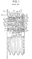
- FIG. 1 shows one type of auxiliary equipment drive apparatus which has been proposed in the past.
- a rotating input member in the form of a hollow input shaft 1 is directly connected to the crankshaft of an unillustrated engine.
- a rotating output member in the form of a pulley 2 is rotatably supported on the input shaft 1 and on a stationary plate 3.
- the pulley 2 comprises a peripheral casing 2a and an end plate 2b which is secured to the casing 2a by screws 2c.
- the pulley 2 drives a number of pieces of unillustrated auxiliary equipment by belts which are wound around the pulley casing 2a.
- the end plate 2b is rotatably supported by the input shaft 1 through a ball bearing 4.
- the stationary plate 3 is secured to a stationary portion of the engine by unillustrated bolts which pass through bolt holes 3a formed in the stationary plate 3.
- a roller bearing 6 is provided between the input shaft 1 and a flange portion of the stationary plate 3 which surrounds the input shaft 1.
- the planetary cone reduction gear 7 has a plurality of planetary cones 8 which are rotatably mounted by their stems on a cone support ring 9 which surrounds the input shaft 1 and can rotate with respect thereto.
- Each of the cones 8 has a first frictional transmission surface 8a which forms the top surface of the cone 8, a second frictional transmission surface 8b which forms the base of the cone 8, and a third frictional transmission surface 8c which forms the periphery of the stem of the cone 8.
- each cone 8 is sloped with respect to the axis of the input shaft 1 so that a line which is parallel to the axis of the input shaft I can be drawn from the vertex of the cone 8 to its base along its top surface.
- the first frictional transmission surface 8a of each cone 8 frictionally engages with the inner surface of a speed change ring 10 which is concentrically disposed with respect to the input shaft 1.
- the speed change ring 10 has a plurality of pins 10a secured to its outer surface. and on each of these pins 10a are rotatably mounted two roller keys 10b and 10c.
- the outer roller keys 10b are disposed inside corresponding axially-extending grooves 2d formed in the inner surface of the peripheral casing 2a of the pulley 2.
- the rotation of the speed change ring 10 is transmitted to the peripheral casing 2a of the pulley 2 by the outer roller keys 10b, causing the pulley 2 to rotate at the same speed as the speed change ring 10. but at the same time.
- the speed change ring 10 is able to freely move in the axial direction of the pulley 2.
- the second frictional transmission.surface 8b of each cone 8 is in frictional engagement with the outer periphery of an input ring 11 which surrounds the input shaft 1.
- the input ring 11 is caused to rotate together with the input shaft 1 by a transmission mechanism 12 comprising a first race 12a and a plurality of balls 12b.
- the balls 12b are held between the undulating surface of the first race 12a and a similar undulating surface of a second race which is formed on the inner portion of the input ring 11.
- the transmission mechanism 12 exerts a torque on the input ring 11 as well as a force in the axial direction which causes the outer end of the input ring 11 to contact with the second frictional transmission surface 8b of each of the planetary cones 8.
- the third frictional transmission surface 8c of each planetary cone 8 is in frictional engagement with the outer peripheral surface of a stationary guide ring 13 which is secured to the stationary plate 3.
- the reduction ratio of the reduction gear 7 can be adjusted by moving the speed change ring 10 in the axial direction of the input shaft 1. and this is accomplished by a reduction ratio adjustment mechanism in the form of an overcurrent electromagnetic brake 15 and a cylindrical cam 16.
- the overcurrent electromagnetic brake 15 has an electromagnetic coil 15a which is mounted on the stationary plate 3 and which uses the stationary plate 3 as a portion of a magnetic path, an electromagnetic pole 15b which is also secured to the stationary plate 3, and a cylindrical overcurrent cup 15c which surrounds the pole 15b and which is made of a material with good electrical conductivity.
- the cylindrical cam -16 is a tubular member having a flange 16a which is integral with the overcurrent cup 15c and a plurality of axially-extending cam surfaces 16b which confront the inner roller keys 10c mounted on the pins 10a of the speed change ring-10.
- the cylindrical cam 16 and the overcurrent cup 15c are rotatably supported by the pulley casing 2a through a ball bearing 17.
- a number of packing rings 18 are disposed between the input shaft 1. the pulley 2. and the stationary plate 3 so as to prevent lubricating oil from leaking from the inside of the pulley 2.
- a pulse pickup 20 is mounted on the stationary plate 3 so as to confront one end of the pulley casing 2a across a small gap.
- the portion of the pulley casing 2a which it confronts has a plurality of slits 2e cut in it at regular intervals around its circumference.
- the pulse pickup 20 produces an electrical output signal in the form of an electrical pulse each time one of the slits 2e passes by it.
- Element number 21 is a waveform shaping circuit which receives the output signal from the pulse pickup 20 and which produces a waveform-shaped output signal.
- Element number 22 is a digital-to-analog converter which receives the output signal from the waveform shaping circuit 21. which is a periodic digital signal which is proportional to the rotational speed of the pulley 2. and converts it into an analog output signal.
- Element number 23 is a load detecting circuit which produces output signals indicative of the load conditions of the engine and of the various pieces of auxiliary equipment which are driven by the drive apparatus.
- Element number 24 is a calculating circuit which receives the output signals from the load detecting circuit 23, computes the optimal rotational speed of the pulley 2 based on the load conditions, and produces a corresponding output signal.
- Element number 25 is a comparator which compares the output signals from the digital-to-analog converter 22 and from the calculating circuit 24 and produces a corresponding output signal.
- Element number 26 is current control circuit which duty controls the exciting current of the electromagnetic coil 15a of the overcurrent electromagnetic brake 15 based on the output signal from the comparator 25.
- this conventional drive apparatus is as follows.
- the input shaft 1 is rotated by the unillustrated engine
- the input ring 11 is caused to rotate by the transmission mechanism 12.
- the planetary cones 8 are caused to rotate about their axes.
- the planetary cones 8 revolve about the input shaft 1, performing planetary motion.
- the frictional engagement between the planetary cones 8 and the speed change ring 10 causes the speed change ring 10 to rotate about the center of the input shaft 1, and this rotation is transmitted to the pulley casing 2a by the outer roller keys 10b.
- the pulley 2 thus rotates at the same speed as the speed change ring 10. and the unillustrated auxiliary equipment is belt-driven by the pulley 2.
- the reduction ratio of the reduction gear 7 can be set at a desired value by moving the speed change ring 10 in the axial direction of the input shaft 1, and this is done by controlling the damping force exerted by the overcurrent electromagnetic brake 15.
- the speed change ring 10 rotates, rotational force is transmitted to the cam surfaces 16b of the cylindrical cam 16 by the inner roller keys 10c, and this causes the cylindrical cam 16 and the overcurrent cap 15c to rotate as a single body at the same speed as the speed change ring 10.
- the electromagnetic coil 15a of the overcurrent electromagnetic brake 15 is excited, a damping force is exerted on the overcurrent cup 15c. and this causes the cam surfaces 16b to press against the inner roller keys lOc.
- the speed change ring 10 will move to the point on the top surfaces of the planetary cones 8 where the longitudinally-directed force exerted on it by the cam surfaces 16b is balanced by the biasing force.
- the damping force exerted on the overcurrent cup 15c By adjusting the damping force exerted on the overcurrent cup 15c, the speed change ring 10 can be moved to any desired position along the top surfaces of the planetary cones 8.
- the damping force produced by the overcurrent electromagnetic brake 15 is automatically controlled by the control circuit illustrated in Figure 2, which automatically adjusts the exciting current of the electromagnetic coil 15a based on operating condition..
- this conventional drive apparatus has the problem that it requires a pulse pickup 20 to detect the rotational speed of the pulley 2, and this increases the weight and the cost of the apparatus. Furthermore, the requirement that slits 2e be provided in the pulley casing 2a increases manufacturing costs. In addition. there is the disadvantage that the pulley casing 2a must be made of a magnetic material, limiting the range of materials which can be employed.
- the present invention is an auxiliary equipment drive apparatus having a rotating input member, a rotating output member, an adjustable speed change mechanism which drivingly connects the input member to the output member, a mechanism for adjusting the reduction ratio of the speed change mechanism, and a control mechanism for controlling the reduction ratio adjusting mechanism in accordance with load conditions.
- the control mechanism is electrically connected to the stator winding of one of the phases of a charging generator which is driven by the drive apparatus.
- the voltage induced in this stator winding serves as an electrical input signal for the control mechanism, indicating the rotational speed of the pulley. Accordingly, it is not necessary to provide a pulse pickup in order to detect the rotational speed of the pulley, it is not necessary to form slits in the pulley, and it is not necessary for the pulley to be made of a magnetic material.
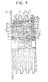
- Figure 3 shows the mechanical portions of this embodiment. Except for the absence of a pulse pickup 20 and slits 2e in a pulley casing 2a. the mechanical portions of this embodiment are identical to the mechanical portions of the conventional apparatus illustrated in Figure 1, and accordingly their explanation will be omitted.
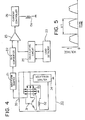
- FIG 4 illustrates a control circuit for controlling the mechanism for adjusting the reduction ratio of the reduction gear 7 shown in Figure 3.
- This control circuit comprises elements 21 through 26, and except for the absence of a pulse pickup 20, this control circuit is identical to the conventional one illustrated in Figure 2.
- a waveform shaping circuit 21 is electrically connected to an output terminal 35 for one phase of a 3-phase charging generator 30 which is belt-driven by the pulley 2 of the drive apparatus.
- the charging generator 30 has stator windings 31 wound in three phases, field coils 32. a 3-phase full-wave rectifier 33 which converts the output of the stator windings 31 into direct current. and a constant voltage regulator 34 which maintains the output voltage of the charging generator 30 constant.
- Output terminal 35 is electrically connected to the stator winding 31 for one phase of the charging generator 30. This output terminal 35 is electrically connected to the waveform shaping circuit 21. and the voltage induced at the output terminal 35 during operation of the charging generator 30 serves as an electrical output signal indicating the rotational speed of the pulley 2.
- the charging generator 30 When the input shaft 1 is rotated by the unillustrated engine, rotation is transmitted to the pulley casing 2a in the same manner as in the conventional apparatus, and the charging generator 30 and other auxiliary equipment are belt-driven-by the pulley 2.
- the charging generator 30 generates electricity, and a voltage having the waveform illustrated in Figure 5 is induced at the output terminal 35. This voltage is applied to the waveform shaping circuit 21 as an electrical input signal. If the rotational speed of the charging generator is N rpm, and the number of poles of the charging generator 30 is P. then the frequency f of this output signal in hertz is NP/120. Because the number of poles P is constant, the frequency f of the output signal from the output terminal 35 is directly proportional to the rotational speed N of the charging generator 30.
- the frequency f is directly proportional to the rotational speed of the pulley 2.
- This output signal can therefore be used instead of an output signal from a pulse detector 20 to indicate the rotational speed of the pulley 2. and the exciting current of the electromagnetic coil 15a is controlled by the control circuit based on the frequency of the output signal from the output terminal 35 in the same manner as in the conventional control circuit shown in Figure 2.
- the rotational speed of the pulley 2 is detected without the need for a pulse pickup 20 or for the provision of slits 2e in the pulley casing 2a. Therefore. it is lighter and less expensive than the conventional apparatus illustrated in Figure 1. For the same reason. the pulley casing 2a does not need to be made of a magnetic material. greatly increasing the range of materials which can be used.
- a planetary cone reduction gear is employed as an adjustable, stepless speed change mechanism. and the mechanism for adjusting the reduction ratio of the speed change mechanism is an overcurrent electromagnetic brake.
- the mechanism for adjusting the reduction ratio of the speed change mechanism is an overcurrent electromagnetic brake.
Landscapes
- Engineering & Computer Science (AREA)
- Mechanical Engineering (AREA)
- General Engineering & Computer Science (AREA)
- Chemical & Material Sciences (AREA)
- Combustion & Propulsion (AREA)
- Transportation (AREA)
- Transmission Devices (AREA)
- Friction Gearing (AREA)
- Pulleys (AREA)
- Control Of Transmission Device (AREA)
Applications Claiming Priority (2)
| Application Number | Priority Date | Filing Date | Title |
|---|---|---|---|
| JP69508/85 | 1985-04-01 | ||
| JP60069508A JPS61228159A (ja) | 1985-04-01 | 1985-04-01 | エンジンの補機駆動装置 |
Publications (3)
| Publication Number | Publication Date |
|---|---|
| EP0196909A2 true EP0196909A2 (de) | 1986-10-08 |
| EP0196909A3 EP0196909A3 (en) | 1987-09-23 |
| EP0196909B1 EP0196909B1 (de) | 1989-07-12 |
Family
ID=13404751
Family Applications (1)
| Application Number | Title | Priority Date | Filing Date |
|---|---|---|---|
| EP86302394A Expired EP0196909B1 (de) | 1985-04-01 | 1986-04-01 | Antriebsanlage für Nebenaggregate |
Country Status (4)
| Country | Link |
|---|---|
| US (1) | US4730516A (de) |
| EP (1) | EP0196909B1 (de) |
| JP (1) | JPS61228159A (de) |
| DE (1) | DE3664295D1 (de) |
Cited By (1)
| Publication number | Priority date | Publication date | Assignee | Title |
|---|---|---|---|---|
| FR2776736A1 (fr) * | 1998-03-24 | 1999-10-01 | Thomson Csf | Variateur de vitesse |
Families Citing this family (8)
| Publication number | Priority date | Publication date | Assignee | Title |
|---|---|---|---|---|
| US4878401A (en) * | 1988-09-02 | 1989-11-07 | Jackson Chung | Combination accessory drive and speed reducer |
| US5484346A (en) * | 1993-11-09 | 1996-01-16 | Koyo Seiko Co., Ltd. | Stepless speed changing apparatus |
| US5796173A (en) * | 1996-05-02 | 1998-08-18 | Chrysler Corporation | Hydraulic fit of turboalternator for hybrid motor vehicle |
| US6071206A (en) * | 1998-05-14 | 2000-06-06 | Ntn Corporation | Two speed traction drive pulley system |
| GB0220443D0 (en) * | 2002-09-03 | 2002-10-09 | Orbital Traction Ltd | A continuously variable drive transmission device |
| US7086981B2 (en) * | 2004-02-18 | 2006-08-08 | The Gates Corporation | Transmission and constant speed accessory drive |
| US7858904B2 (en) * | 2005-01-20 | 2010-12-28 | Illinois Tool Works Inc. | System and method of controlling auxiliary/weld power outputs of a welding-type apparatus |
| TWI513131B (zh) * | 2013-07-03 | 2015-12-11 | Universal Scient Ind Shanghai | 電壓調節器及其過低電壓保護電路 |
Family Cites Families (10)
| Publication number | Priority date | Publication date | Assignee | Title |
|---|---|---|---|---|
| US2836994A (en) * | 1953-09-10 | 1958-06-03 | Weber Max | Infinitely variable friction transmission with conical planetary rollers |
| US3108496A (en) * | 1961-01-30 | 1963-10-29 | Kashihara Manabu | Infinitely variable speed change gear |
| US3504187A (en) * | 1965-12-08 | 1970-03-31 | Alternac | Electric generator and speed control system therefor |
| JPS6030863B2 (ja) * | 1977-06-14 | 1985-07-18 | シンポ工業株式会社 | 摩擦無段変速機 |
| JPS545164A (en) * | 1977-06-14 | 1979-01-16 | Shinpo Kogyo Kk | Friction-type stepless change gear |
| JPS5886434A (ja) * | 1981-11-17 | 1983-05-24 | Hitachi Koki Co Ltd | 傾斜式上澄液分取機構 |
| JPS58200838A (ja) * | 1982-05-19 | 1983-11-22 | Honda Motor Co Ltd | 変速装置 |
| JPS58201536A (ja) * | 1982-05-19 | 1983-11-24 | 三菱電機株式会社 | 車両用充電制御マイクロコンピユ−タ装置 |
| JPS59231252A (ja) * | 1983-06-14 | 1984-12-25 | Shinpo Kogyo Kk | 車両の自動変速装置 |
| JPS60153828U (ja) * | 1984-03-23 | 1985-10-14 | 三菱電機株式会社 | エンジンの補機駆動装置 |
-
1985
- 1985-04-01 JP JP60069508A patent/JPS61228159A/ja active Pending
-
1986
- 1986-03-31 US US06/846,141 patent/US4730516A/en not_active Expired - Lifetime
- 1986-04-01 EP EP86302394A patent/EP0196909B1/de not_active Expired
- 1986-04-01 DE DE8686302394T patent/DE3664295D1/de not_active Expired
Cited By (1)
| Publication number | Priority date | Publication date | Assignee | Title |
|---|---|---|---|---|
| FR2776736A1 (fr) * | 1998-03-24 | 1999-10-01 | Thomson Csf | Variateur de vitesse |
Also Published As
| Publication number | Publication date |
|---|---|
| EP0196909A3 (en) | 1987-09-23 |
| EP0196909B1 (de) | 1989-07-12 |
| JPS61228159A (ja) | 1986-10-11 |
| US4730516A (en) | 1988-03-15 |
| DE3664295D1 (en) | 1989-08-17 |
Similar Documents
| Publication | Publication Date | Title |
|---|---|---|
| US7797815B2 (en) | Control of a dual rotor electromagnetic machine | |
| US4885493A (en) | Output voltage control apparatus of a permanent magnet alternator | |
| US5675203A (en) | Motor/generator arrangement having a movable common stator | |
| US4654551A (en) | Permanent magnet excited alternator compressor with brushless DC control | |
| EP0158158B1 (de) | Von einem Motor getriebene Antriebseinheit für eine Hilfsvorrichtung | |
| US4651082A (en) | Generating apparatus with an adjustable speed change mechanism | |
| JPH0158386B2 (de) | ||
| JPS63198558A (ja) | 調整可能永久磁石交流機 | |
| US10122309B2 (en) | Generator comprising a variable speed magnetic gear | |
| EP0196909B1 (de) | Antriebsanlage für Nebenaggregate | |
| US4437846A (en) | Speed limiting rotary coupling | |
| US7713157B2 (en) | Planetary gear controlled alternator | |
| EP0058025B1 (de) | Drehende elektrische Maschinen | |
| JP2000502875A (ja) | 電気モータ | |
| CN114337186B (zh) | 一种永磁涡流调速装置 | |
| US6127754A (en) | Master synchronizer motor | |
| JPH06141401A (ja) | 電動車両用駆動装置 | |
| US6208049B1 (en) | Motor vehicle auxiliaries drive assembly | |
| US4634404A (en) | Method of controlling rotation of a V-belt drive | |
| US4730515A (en) | Drive apparatus for engine auxiliary equipment | |
| GB2062974A (en) | Electric motor | |
| EP0993098A2 (de) | Vorrichtung zur Regelung eines Wechselstromgenerators für Fahrzeuge | |
| EP0196908A2 (de) | Antriebsvorrichtung für Hilfsaggregat | |
| JPH0558190A (ja) | エンジンから補機への動力伝達装置 | |
| JPH0558189A (ja) | エンジンから補機への動力伝達装置 |
Legal Events
| Date | Code | Title | Description |
|---|---|---|---|
| PUAI | Public reference made under article 153(3) epc to a published international application that has entered the european phase |
Free format text: ORIGINAL CODE: 0009012 |
|
| AK | Designated contracting states |
Kind code of ref document: A2 Designated state(s): DE FR GB |
|
| PUAL | Search report despatched |
Free format text: ORIGINAL CODE: 0009013 |
|
| RHK1 | Main classification (correction) |
Ipc: B60K 25/02 |
|
| AK | Designated contracting states |
Kind code of ref document: A3 Designated state(s): DE FR GB |
|
| 17P | Request for examination filed |
Effective date: 19870929 |
|
| 17Q | First examination report despatched |
Effective date: 19880330 |
|
| GRAA | (expected) grant |
Free format text: ORIGINAL CODE: 0009210 |
|
| AK | Designated contracting states |
Kind code of ref document: B1 Designated state(s): DE FR GB |
|
| REF | Corresponds to: |
Ref document number: 3664295 Country of ref document: DE Date of ref document: 19890817 |
|
| REG | Reference to a national code |
Ref country code: GB Ref legal event code: 727 |
|
| ET | Fr: translation filed | ||
| REG | Reference to a national code |
Ref country code: GB Ref legal event code: 727A |
|
| REG | Reference to a national code |
Ref country code: GB Ref legal event code: 727 |
|
| REG | Reference to a national code |
Ref country code: GB Ref legal event code: SP |
|
| PLBE | No opposition filed within time limit |
Free format text: ORIGINAL CODE: 0009261 |
|
| STAA | Information on the status of an ep patent application or granted ep patent |
Free format text: STATUS: NO OPPOSITION FILED WITHIN TIME LIMIT |
|
| 26N | No opposition filed | ||
| REG | Reference to a national code |
Ref country code: GB Ref legal event code: IF02 |
|
| PGFP | Annual fee paid to national office [announced via postgrant information from national office to epo] |
Ref country code: GB Payment date: 20020327 Year of fee payment: 17 |
|
| PGFP | Annual fee paid to national office [announced via postgrant information from national office to epo] |
Ref country code: FR Payment date: 20020410 Year of fee payment: 17 Ref country code: DE Payment date: 20020410 Year of fee payment: 17 |
|
| PG25 | Lapsed in a contracting state [announced via postgrant information from national office to epo] |
Ref country code: GB Free format text: LAPSE BECAUSE OF NON-PAYMENT OF DUE FEES Effective date: 20030401 |
|
| PG25 | Lapsed in a contracting state [announced via postgrant information from national office to epo] |
Ref country code: DE Free format text: LAPSE BECAUSE OF NON-PAYMENT OF DUE FEES Effective date: 20031101 |
|
| GBPC | Gb: european patent ceased through non-payment of renewal fee |
Effective date: 20030401 |
|
| PG25 | Lapsed in a contracting state [announced via postgrant information from national office to epo] |
Ref country code: FR Free format text: LAPSE BECAUSE OF NON-PAYMENT OF DUE FEES Effective date: 20031231 |
|
| REG | Reference to a national code |
Ref country code: FR Ref legal event code: ST |