EP0196908A2 - Antriebsvorrichtung für Hilfsaggregat - Google Patents
Antriebsvorrichtung für Hilfsaggregat Download PDFInfo
- Publication number
- EP0196908A2 EP0196908A2 EP86302392A EP86302392A EP0196908A2 EP 0196908 A2 EP0196908 A2 EP 0196908A2 EP 86302392 A EP86302392 A EP 86302392A EP 86302392 A EP86302392 A EP 86302392A EP 0196908 A2 EP0196908 A2 EP 0196908A2
- Authority
- EP
- European Patent Office
- Prior art keywords
- bushing
- bolt
- motor
- metallic
- stationary plate
- Prior art date
- Legal status (The legal status is an assumption and is not a legal conclusion. Google has not performed a legal analysis and makes no representation as to the accuracy of the status listed.)
- Withdrawn
Links
Images
Classifications
-
- F—MECHANICAL ENGINEERING; LIGHTING; HEATING; WEAPONS; BLASTING
- F16—ENGINEERING ELEMENTS AND UNITS; GENERAL MEASURES FOR PRODUCING AND MAINTAINING EFFECTIVE FUNCTIONING OF MACHINES OR INSTALLATIONS; THERMAL INSULATION IN GENERAL
- F16H—GEARING
- F16H35/00—Gearings or mechanisms with other special functional features
- F16H35/06—Gearings designed to allow relative movement between supports thereof without ill effects
-
- F—MECHANICAL ENGINEERING; LIGHTING; HEATING; WEAPONS; BLASTING
- F02—COMBUSTION ENGINES; HOT-GAS OR COMBUSTION-PRODUCT ENGINE PLANTS
- F02B—INTERNAL-COMBUSTION PISTON ENGINES; COMBUSTION ENGINES IN GENERAL
- F02B67/00—Engines characterised by the arrangement of auxiliary apparatus not being otherwise provided for, e.g. the apparatus having different functions; Driving auxiliary apparatus from engines, not otherwise provided for
- F02B67/04—Engines characterised by the arrangement of auxiliary apparatus not being otherwise provided for, e.g. the apparatus having different functions; Driving auxiliary apparatus from engines, not otherwise provided for of mechanically-driven auxiliary apparatus
- F02B67/06—Engines characterised by the arrangement of auxiliary apparatus not being otherwise provided for, e.g. the apparatus having different functions; Driving auxiliary apparatus from engines, not otherwise provided for of mechanically-driven auxiliary apparatus driven by means of chains, belts, or like endless members
-
- F—MECHANICAL ENGINEERING; LIGHTING; HEATING; WEAPONS; BLASTING
- F16—ENGINEERING ELEMENTS AND UNITS; GENERAL MEASURES FOR PRODUCING AND MAINTAINING EFFECTIVE FUNCTIONING OF MACHINES OR INSTALLATIONS; THERMAL INSULATION IN GENERAL
- F16H—GEARING
- F16H15/00—Gearings for conveying rotary motion with variable gear ratio, or for reversing rotary motion, by friction between rotary members
- F16H15/48—Gearings for conveying rotary motion with variable gear ratio, or for reversing rotary motion, by friction between rotary members with members having orbital motion
- F16H15/50—Gearings providing a continuous range of gear ratios
-
- F—MECHANICAL ENGINEERING; LIGHTING; HEATING; WEAPONS; BLASTING
- F16—ENGINEERING ELEMENTS AND UNITS; GENERAL MEASURES FOR PRODUCING AND MAINTAINING EFFECTIVE FUNCTIONING OF MACHINES OR INSTALLATIONS; THERMAL INSULATION IN GENERAL
- F16H—GEARING
- F16H57/00—General details of gearing
- F16H57/0006—Vibration-damping or noise reducing means specially adapted for gearings
-
- F—MECHANICAL ENGINEERING; LIGHTING; HEATING; WEAPONS; BLASTING
- F02—COMBUSTION ENGINES; HOT-GAS OR COMBUSTION-PRODUCT ENGINE PLANTS
- F02B—INTERNAL-COMBUSTION PISTON ENGINES; COMBUSTION ENGINES IN GENERAL
- F02B2275/00—Other engines, components or details, not provided for in other groups of this subclass
- F02B2275/06—Endless member is a belt
Definitions
- This invention relates to a drive apparatus for the auxiliary equipment of a motor. and more particularly but not exclusively to the case in which the motor is the engine of an automobile.
- auxiliary equipment such as charging generators. water pumps. air conditioning compressors. and oil pumps for hydraulic servo steering is belt-driven by a drive pulley mounted on the end of the crankshaft of the engine.
- This auxiliary equipment is generally designed to be operated at low speeds. and if driven at the same speed as the engine when the engine is running at high speeds. the operation of the equipment would produce considerable power losses. Therefore.
- means are generally provided for adjusting the rotational speed of the drive pulley for the auxiliary equipment with respect to the rotational speed of the engine so that the auxiliary equipment can be operated at suitable speeds.
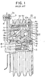
- FIG. 1 shows one type of auxiliary equipment drive apparatus which has been proposed in the past.
- a rotating input member in the form of a hollow input shaft 1 is directly connected to the crankshaft 2 of an engine by a bolt 3.
- a rotating output member in the form of a pulley 4 is rotatably supported on the input shaft 1 and on a stationary plate 5.
- the pulley 4 comprises a peripheral casing 4a and an end plate 4b which is secured to the casing 4a by screws 4c.
- the Pulley 4 drives a number of pieces of unillustrated auxiliary equipment by belts which are wound around the pulley casing 4a.
- the end plate 4b is rotatably supported by the input shaft 1 through a ball bearing 6.
- the stationary plate 5 is secured to a stationary portion of the engine in the form of a boss 8 by bolts 9 which pass through bolt holes 5a formed in the stationary plate 5.
- a roller bearing 10 is provided between the input shaft 1 and a flange portion of the stationary plate 5 which surrounds the input shaft 1.
- the planetary cone reduction gear 11 has a plurality of planetary cones 12 which are rotatably mounted by their stems on a cone support ring 13 which surrounds the input shaft 1 and can rotate with respect thereto.
- Each of the cones 12 has a first frictional transmission surface 12a which forms the top surface of the cone 12.
- a second frictional transmission surface 12b which forms the base of the cone 12, and a third frictional transmission surface 12c which forms the periphery of the stem of the cone 12.
- each cone 12 is sloped with respect to the axis of the input shaft 1 so that a line which is parallel to the axis of the input shaft 1 can be drawn from the vertex of the cone 12 to its base along its top surface.
- the first frictional transmission surface 12a of each cone 12 frictionally engages with the inner surface of a speed change ring 14 which is concentrically disposed with respect to the input shaft 1.
- the speed change ring 14 has a plurality of pins 1 4a secured to its outer surface. and on each of these pins 14a are rotatably mounted two roller keys 14b and 14c.
- the outer roller keys 14b are disposed inside corresponding axially-extending grooves 4d formed in the inner surface of the peripheral casing 4a of the pulley 4.
- the rotation of the speed change ring 14 is transmitted to the peripheral casing 4a of the pulley 4 by the outer roller keys 14b. causing the pulley 4 to rotate at the same speed as the speed change ring 14. but at the same time. the speed change ring 14 is able to freely move in the axial direction of the pulley 4.
- the second frictional transmission surface 12b of each cone 12 is in frictional engagement with the outer periphery of an input ring 15 which surrounds the input shaft 1.
- the input ring 15 is caused to rotate together with the input shaft 1 by a transmission mechanism 16 comprising a first race 16a and a plurality of balls 16b.
- the balls 16b are held between the undulating surface of the first race 16a and a similar undulating surface of a second race which is formed on the inner portion of the input ring 15.
- the transmission mechanism 16 exerts a torque on the input ring 15 as well as a force in the axial direction which causes the outer end of the input ring 15 to contact with the second frictional transmission surface 12b of each of the planetary cones 12.
- the third frictional transmission surface 12c of each planetary cone 12 is in frictional engagement with the outer peripheral surface of a stationary guide ring 17 which is secured to the stationary plate 5.
- the reduction ratio of the reduction gear 11 can be adjusted by moving the speed change ring 14 in the axial direction of the input shaft 1. and this is accomplished by a reduction ratio adjustment mechanism in the form of an overcurrent electromagnetic brake 19 and a cylindrical cam 20.
- the overcurrent electromagnetic brake 19 has an electromagnetic coil 19a which is mounted on the stationary plate 5 and which uses the stationary plate 5 as a portion of a magnetic path, an electromagnetic pole 19b which is also secured to the stationary plate 5. and a cylindrical overcurrent cup 19c which surrounds the pole 19b and which is made of a material with good electrical conductivity.
- the cylindrical cam 20 is a tubular member having a flange 20a which is integral with the overcurrent cup 19c and a plurality of axially-extending cam surfaces 20b which confront the inner roller keys 14c mounted on the pins 14a of the speed change ring 14.
- the cylindrical cam 20 and the overcurrent cup 19c are rotatably supported by the pulley casing 4a through a ball bearing 21.
- a number of packing rings 22 are disposed between the input shaft 1. the pulley 4. and the stationary plate 5 so as to prevent lubricating oil from leaking from the inside of the pulley 4.
- this conventional drive apparatus is as follows.
- the input shaft 1 is rotated by the crankshaft 2 of the engine.
- the input ring 15 is caused to rotate by the transmission mechanism 16.
- the planetary cones 12 are caused to rotate about their axes.
- the planetary cones 12 revolve about the input shaft 1. performing planetary motion.
- the frictional engagement between the planetary cones 12 and the speed change ring 14 causes the speed change ring 14 to rotate about the center of the input shaft 1. and this rotation is transmitted to the pulley casing 4a by the outer roller keys 14b.
- the pulley 4 thus rotates at the same speed as the speed change ring 14. and the unillustrated auxiliary equipment is belt-driven by the pulley 4.
- the reduction ratio of the reduction gear 11 can be set at a desired value by moving the speed change ring 14 in the axial direction of the input shaft 1. and this is done by controlling the damping force exerted by the overcurrent electromagnetic brake 19.
- rotational force is transmitted to the cam surfaces 20b of the cylindrical cam 20 by the inner roller keys 14c. and this causes the cylindrical cam 20 and the overcurrent cap 19c to rotate as a single body at the same speed as the speed change ring 14.
- the electromagnetic coil 19a of the overcurrent electromagnetic brake 19 is excited. a damping force is exerted on the overcurrent cup 19c. and this causes the cam surfaces 20b to press against the inner roller keys 14c.
- the speed change ring 14 will move to the point on the top surfaces of the planetary cones 12 where the longitudinally-directed force exerted on it by the cam surfaces 20b is balanced by the biasing force.
- the damping force exerted on the overcurrent cup 19c By adjusting the damping force exerted on the overcurrent cup 19c. the speed change ring 14 can be moved to any desired position along the top surfaces of the planetary cones 12.
- the damping force produced by the overcurrent electromagnetic brake 19 is automatically controlled by an unillustrated control circuit which automatically adjusts the exciting current of the electromagnetic coil 19a based on operating conditions.
- the conventional drive apparatus described above is mounted on an engine by being directly connected to bosses 8 of the engine by bolts 9.
- This manner of mounting the apparatus can easily result in abnormal vibrations, since there is a difference in the modes and phases of vibration of the crankshaft 2 and the boss 8. These abnormal vibration reduce the performance of the apparatus.
- the mounting of the apparatus on the engine bosses 8 can produce strains in the apparatus. which reduces the durability of bearings and other parts. In order to prevent such strains. it is necessary to machine the boss 8 and the stationary plate 5 in order to ensure positional accuracy. and this increases manufacturing costs.
- An auxiliary equipment drive apparatus has a stationary plate which is mounted on an engine boss by a fastener such as a bolt.
- a shock absorbing member is disposed between the stationary plate of the drive apparatus and the fastener. The shock absorbing member absorbs vibrations and prevents abnormal vibrations from developing in the drive apparatus. Furthermore. the shock absorbing member compensates for dimensional inaccuracies and prevents stresses from developing in the drive apparatus when it is mounted on an engine.
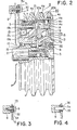
- FIG. 2 is a partially cross-sectional side view of a first embodiment of the present invention. Elements bearing the same reference numbers as those in the conventional apparatus of Figure 1 are identical in structure and function, and their explanation will be omitted.
- This apparatus differs from the conventional apparatus of Figure 1 in the provision of a shock absorbing member between the stationary plate 5 of the apparatus and a fastener in the form of a bolt 9 by which the stationary plate 5 is secured to a boss 8 of an engine.
- the shock absorbing member comprises a metallic, flanged, inner bushing 30 and a flanged, outer bushing 31 made of an elastic material such as rubber.
- the metallic inner bushing 30 fits over the bolt 9 with the flanged end abutting against the surface of the boss 8 and with the other end abutting against the head of the bolt 9.
- the outer bushing 31 fits over the inner bushing 30 with its flanged end held between the flange of the inner bushing 30 and the stationary plate 5. and with the other end abutting against the head of the bolt 9.
- the manner in which drive force is transmitted from the ' crankshaft 2 to the pulley 4 in this embodiment is identical to that for the previously-described conventional apparatus.
- the crankshaft 2 of the engine and the engine boss 9 vibrate with respect to one another due to differences in their modes and phases of vibration.
- the shock absorbing member can absorb these vibrations and prevent abnormal vibrations from developing in the drive apparatus. thereby improving the performance of the apparatus.
- the outer bushing 31 of the shock absorbing member is made of an elastic material which can easily deform, it can compensate for dimensional errors in the boss 8 and the stationary plate 5 so that stresses will not develop in the apparatus due to small dimensional errors when it is mounted on the engine boss 8. Accordingly, it is not necessary to manufacture the boss 8 and the stationary plate 5 so as to have high dimensional accuracy, and their manufacturing costs can be decreased.
- FIG. 3 illustrates a portion of a second embodiment of the present invention.
- a shock absorbing member comprises a metallic, inner bushing 32 which fits over a bolt 9. an metallic. outer bushing 34 which surrounds the metallic inner bushing 32 with a space therebetween. and a middle bushing 33 made of an elastic material such as rubber which is disposed between the inner bushing 32 and the outer bushing 34.
- the metallic. outer bushing 34 is secured to the inner surface of the bolt hole 5a in the stationary plate 5 by press-fitting or other means.
- the middle bushing 33 is secured to the inner bushing 32 and the outer bushing 34 by a suitable method such as melting or bonding.
- This embodiment is otherwise identical to the first embodiment. and the shock absorbing member provides the same benefits as in that embodiment.
- Figure 4 illustrates a portion of a third embodiment of the present invention.
- a pin 35 which is secured to the engine boss 8 is used as a fastener to mount the drive apparatus on the boss 8.
- the shock absorbing member comprises an elastic ring 36 made of rubber or the like which is mounted inside the bolt hole 5a of the stationary plate and which is secured to the engine boss 8 by suitable means.
- This embodiment is otherwise identical to the embodiment of Figure 2. and the shock absorbing member provides the same effects as in that embodiment. Furthermore. because a bolt 9 is not needed. the drive apparatus can be more easily mounted on the boss 8.
- a planetary cone reduction gear is employed as an adjustable. stepless speed change mechanism, and the mechanism for adjusting the reduction ratio of the speed change mechanism is an overcurrent electromagnetic brake.
- the mechanism for adjusting the reduction ratio of the speed change mechanism is an overcurrent electromagnetic brake.
Landscapes
- Engineering & Computer Science (AREA)
- General Engineering & Computer Science (AREA)
- Mechanical Engineering (AREA)
- Chemical & Material Sciences (AREA)
- Combustion & Propulsion (AREA)
- Friction Gearing (AREA)
- Retarders (AREA)
- General Details Of Gearings (AREA)
- Devices For Conveying Motion By Means Of Endless Flexible Members (AREA)
- Pulleys (AREA)
Applications Claiming Priority (2)
| Application Number | Priority Date | Filing Date | Title |
|---|---|---|---|
| JP60069509A JPS61228162A (ja) | 1985-04-01 | 1985-04-01 | エンジンの補機駆動装置 |
| JP69509/85 | 1985-04-01 |
Publications (2)
| Publication Number | Publication Date |
|---|---|
| EP0196908A2 true EP0196908A2 (de) | 1986-10-08 |
| EP0196908A3 EP0196908A3 (de) | 1987-10-28 |
Family
ID=13404780
Family Applications (1)
| Application Number | Title | Priority Date | Filing Date |
|---|---|---|---|
| EP86302392A Withdrawn EP0196908A3 (de) | 1985-04-01 | 1986-04-01 | Antriebsvorrichtung für Hilfsaggregat |
Country Status (2)
| Country | Link |
|---|---|
| EP (1) | EP0196908A3 (de) |
| JP (1) | JPS61228162A (de) |
Cited By (1)
| Publication number | Priority date | Publication date | Assignee | Title |
|---|---|---|---|---|
| WO2006012955A1 (de) * | 2004-07-31 | 2006-02-09 | Schaeffler Kg | Zugmitteltrieb |
Family Cites Families (4)
| Publication number | Priority date | Publication date | Assignee | Title |
|---|---|---|---|---|
| JPH0239666B2 (ja) * | 1983-01-17 | 1990-09-06 | Shinho Kogyo Kk | Mudanhensokusochi |
| JPS59155633A (ja) * | 1983-02-21 | 1984-09-04 | Honda Motor Co Ltd | 補機駆動用自動変速装置 |
| JPS59194153A (ja) * | 1983-04-15 | 1984-11-02 | Honda Motor Co Ltd | 自動変速装置 |
| JPS59194152A (ja) * | 1983-04-15 | 1984-11-02 | Honda Motor Co Ltd | 自動変速装置 |
-
1985
- 1985-04-01 JP JP60069509A patent/JPS61228162A/ja active Pending
-
1986
- 1986-04-01 EP EP86302392A patent/EP0196908A3/de not_active Withdrawn
Cited By (1)
| Publication number | Priority date | Publication date | Assignee | Title |
|---|---|---|---|---|
| WO2006012955A1 (de) * | 2004-07-31 | 2006-02-09 | Schaeffler Kg | Zugmitteltrieb |
Also Published As
| Publication number | Publication date |
|---|---|
| EP0196908A3 (de) | 1987-10-28 |
| JPS61228162A (ja) | 1986-10-11 |
Similar Documents
| Publication | Publication Date | Title |
|---|---|---|
| US4738164A (en) | Centrifugal force adjusted infinitely variable drive apparatus for auxiliary equipment | |
| US4926992A (en) | Electromagnetically operable friction-disk clutch | |
| JPH0139865Y2 (de) | ||
| JPH0158386B2 (de) | ||
| US6848401B2 (en) | Valve timing adjusting device | |
| EP0250551A1 (de) | Generator mit doppeldauermagnet | |
| KR940018564A (ko) | 스크롤형 유체기구 | |
| JPH09504347A (ja) | 渦巻圧縮機用平行調節装置 | |
| US5445247A (en) | Damping unit | |
| US20210048095A1 (en) | Compound harmonic gear motor configured for continuous output rotation | |
| CN114337159A (zh) | 一种可穿轴安装的电机式在线自动平衡装置 | |
| EP0196909B1 (de) | Antriebsanlage für Nebenaggregate | |
| EP0196908A2 (de) | Antriebsvorrichtung für Hilfsaggregat | |
| CN114337186B (zh) | 一种永磁涡流调速装置 | |
| KR20040094407A (ko) | 다중 시동장치-발전기 수단을 구비하는 클러치-바이-와이어 | |
| EP1657803B1 (de) | Fahrzeuggenerator mit magnetischem Schwankungsuppressor, zum Unterdrücken von Schwankungen in der Rotationbewegung | |
| KR0136090B1 (ko) | 전자 클러치 | |
| JPH0271946A (ja) | フライス・ボール盤用スピンドル・ユニット | |
| CN111224476A (zh) | 一种圆盘电机 | |
| JPH0217695B2 (de) | ||
| EP0993098A2 (de) | Vorrichtung zur Regelung eines Wechselstromgenerators für Fahrzeuge | |
| CN221033831U (zh) | 一种蜗轮蜗杆行星无级调速装置 | |
| JP2583955Y2 (ja) | 電磁クラッチ | |
| KR19990062106A (ko) | 공작기계의 로타리 테이블 구조 | |
| JPS62160052A (ja) | ボールねじ付中空軸モータ |
Legal Events
| Date | Code | Title | Description |
|---|---|---|---|
| PUAI | Public reference made under article 153(3) epc to a published international application that has entered the european phase |
Free format text: ORIGINAL CODE: 0009012 |
|
| AK | Designated contracting states |
Kind code of ref document: A2 Designated state(s): DE FR GB |
|
| PUAL | Search report despatched |
Free format text: ORIGINAL CODE: 0009013 |
|
| AK | Designated contracting states |
Kind code of ref document: A3 Designated state(s): DE FR GB |
|
| STAA | Information on the status of an ep patent application or granted ep patent |
Free format text: STATUS: THE APPLICATION IS DEEMED TO BE WITHDRAWN |
|
| 18D | Application deemed to be withdrawn |
Effective date: 19880429 |
|
| RIN1 | Information on inventor provided before grant (corrected) |
Inventor name: KANEYUKI, KAZUTOSHIC/O HIMEJI WORKS |