EP0195981B1 - Printing mechanism with a printing head movable in print line direction and a print hammer bar as platen backing - Google Patents
Printing mechanism with a printing head movable in print line direction and a print hammer bar as platen backing Download PDFInfo
- Publication number
- EP0195981B1 EP0195981B1 EP86103352A EP86103352A EP0195981B1 EP 0195981 B1 EP0195981 B1 EP 0195981B1 EP 86103352 A EP86103352 A EP 86103352A EP 86103352 A EP86103352 A EP 86103352A EP 0195981 B1 EP0195981 B1 EP 0195981B1
- Authority
- EP
- European Patent Office
- Prior art keywords
- carrier
- transport roller
- printing
- transport
- disposed
- Prior art date
- Legal status (The legal status is an assumption and is not a legal conclusion. Google has not performed a legal analysis and makes no representation as to the accuracy of the status listed.)
- Expired - Lifetime
Links
Images

Classifications
-
- B—PERFORMING OPERATIONS; TRANSPORTING
- B41—PRINTING; LINING MACHINES; TYPEWRITERS; STAMPS
- B41J—TYPEWRITERS; SELECTIVE PRINTING MECHANISMS, i.e. MECHANISMS PRINTING OTHERWISE THAN FROM A FORME; CORRECTION OF TYPOGRAPHICAL ERRORS
- B41J11/00—Devices or arrangements of selective printing mechanisms, e.g. ink-jet printers or thermal printers, for supporting or handling copy material in sheet or web form
- B41J11/20—Platen adjustments for varying the strength of impression, for a varying number of papers, for wear or for alignment, or for print gap adjustment
-
- B—PERFORMING OPERATIONS; TRANSPORTING
- B41—PRINTING; LINING MACHINES; TYPEWRITERS; STAMPS
- B41J—TYPEWRITERS; SELECTIVE PRINTING MECHANISMS, i.e. MECHANISMS PRINTING OTHERWISE THAN FROM A FORME; CORRECTION OF TYPOGRAPHICAL ERRORS
- B41J11/00—Devices or arrangements of selective printing mechanisms, e.g. ink-jet printers or thermal printers, for supporting or handling copy material in sheet or web form
- B41J11/02—Platens
- B41J11/08—Bar or like line-size platens
Description
Die Erfindung betrifft ein Druckwerk der im Oberbegriff des Anspruches 1 bzw. des Anspruches 4 genannten Art.The invention relates to a printing unit of the type mentioned in the preamble of claim 1 and
Der Aufzeichnungsträger wird bei derartigen Druckwerken durch die Transporteinrichtung senkrecht zur Zeilenrichtung im allgemeinen in Zeilensprüngen weitertransportiert und durch den Druckkopf zeilenweise bedruckt. Die Druckköpfe moderner Druckwerke, beispielsweise in Zeilenrichtung verfahrbare Nadeldruckköpfe oder Tintenmosaikdruckköpfe oder auch in zeilenrichtung unbewegliche Thermodruckleisten müssen während des Druckvorganges mit großer Genauigkeit in einem sehr geringen Abstand zum Aufzeichnungsträger gehalten bzw. mit einer bestimmten Andruckkraft gegen den Aufzeichnungsträger gehalten werden. Um den genauen Abstand bzw. Andruck auch bei Aufzeichnungsträgern unterschiedlicher Stärke sicherzustellen, ist es schon bekannt, die Stärke des Aufzeichnungsträgers durch eine Fühleranordnung festzustellen und den Abstand des Druckkopfes vom Druckgegenlager durch die Fühleranordnung zu steuern. Typische Anwendungsbeispiele für Druckwerke der gattungsgemäßen Art sind die Druckwerke von Belegdruckern in Registrierkassen, die in Transportrichtung geschuppte Belege verarbeiten müssen, sowie von Druckern zum Bedrucken von Sparkassenbüchern oder dergleichen. Es sei an dieser Stelle bemerkt, daß das Druckgegenlager eine beliebige, geeignete Form hat und beispielsweise als Riegel mit einer ebenen Schreibfläche oder als drehbare Druckwalze ausgebildet sein kann.In such printing units, the recording medium is generally transported in line jumps by the transport device perpendicular to the line direction and printed line by line by the print head. The print heads of modern printing units, for example needle print heads or ink mosaic print heads that can be moved in the line direction or thermal print bars that are immobile in the line direction, must be kept with great accuracy at a very short distance from the recording medium during the printing process or must be held against the recording medium with a certain pressure force. In order to ensure the exact distance or pressure even in the case of recording media of different thicknesses, it is already known to determine the thickness of the recording media by means of a sensor arrangement and to control the distance of the print head from the platen by the sensor arrangement. Typical application examples for printing units of the generic type are the printing units of receipt printers in cash registers, which have to process shingled receipts in the transport direction, and of printers for printing savings bank books or the like. It should be noted at this point that the platen has any suitable shape and can be designed, for example, as a bar with a flat writing surface or as a rotatable pressure roller.
Es ist bereits eine Konstruktion bekannt, bei der die Fühleranordnung durch eine an einem Schwenkrahmen angeordnete Fühlerrolle oder -walze gebildet ist, die durch Federmittel gegen den auf dem fest im Druckergehäuse angeordneten Druckbalken aufliegenden Aufzeichnungsträger angelegt wird (DE-PS 22 48 262). An dem Schwenkarm ist eine parallel zur Zeilenrichtung sich erstreckende Führungsleiste befestigt, gegen die der senkrecht zur Schreibebene bewegliche Druckkopf über Führungsrollen federnd anliegt. Diese Einrichtung dient ausschließlich zur Steuerung des Abstandes zwischen dem Druckkopf und dem Druckbalken. Sie muß zusätzlich noch mit nicht dargestellten Mitteln zum Abheben der Fühlerrollen und des Druckkopfes ausgestattet sein. Außerdem muß unabhängig von den in der DE-PS 22 48 262 beschriebenen Bauteilen eine Einrichtung zum Transport des Aufzeichnungsträgers vorgesehen sein. Diese umfaßt im allgemeinen mit einem Antrieb verbundene Transportrollen, Gegendruckrollen sowie Mittel zum Anlegen der Transportrollen gegen den Aufzeichnungsträger sowie zum Abheben der Transportrollen, wenn ein Aufzeichnungsträger eingelegt werden soll.A construction is already known in which the sensor arrangement is formed by a sensor roller or roller arranged on a swivel frame, which is formed by spring means is placed against the recording medium resting on the pressure bar fixedly arranged in the printer housing (DE-PS 22 48 262). A guide bar extending parallel to the line direction is fastened to the swivel arm, against which the print head, which is movable perpendicular to the writing plane, rests resiliently via guide rollers. This device is used only to control the distance between the print head and the print bar. You must also be equipped with means, not shown, for lifting the sensor rollers and the print head. In addition, a device for transporting the recording medium must be provided regardless of the components described in DE-PS 22 48 262. This generally comprises transport rollers connected to a drive, counter-pressure rollers and means for placing the transport rollers against the recording medium and for lifting the transport rollers when a recording medium is to be inserted.
Die bekannte Einrichtung ist in ihrem Aufbau sehr aufwendig, da sie neben dem unabdingbaren Transportsystem mit seinen Antriebs- und Verstelleinrichtungen eine davon unabhängige Fühleranordnung aufweist, die ihrerseits eine Reihe von beweglich gelagerten Bauteilen sowie Mittel zum Betätigen der Fühleranordnung besitzt. Ein weiterer Nachteil der bekannten Konstruktion wird darin gesehen, daß die Übertragung der Stellung der Fühlerrolle auf den Druckkopf über eine Reihe von Lagerstellen geht, welche beim Anlegen oder Abheben der Fühleranordnung bewegt werden und die einem besonders hohen Verschleiß unterliegen. Dieser Verschleiß äußert sich in einer zunehmenden Dejustierung des Druckkopfes im Verlaufe des Einsatzes des Druckwerkes, so daß eine regelmäßige Nachjustierung bzw. ein regelmäßiger Austausch von Teilen der Fühleranordnung erforderlich ist.The structure of the known device is very complex since, in addition to the indispensable transport system with its drive and adjustment devices, it has an independent sensor arrangement, which in turn has a number of movably mounted components and means for actuating the sensor arrangement. Another disadvantage of the known construction is seen in the fact that the transfer of the position of the sensor roller to the print head takes place via a series of bearing points which are moved when the sensor arrangement is put on or taken off and which are subject to particularly high wear. This wear manifests itself in an increasing misalignment of the printhead in the course of the use of the printing unit, so that a regular readjustment or a regular exchange of parts of the sensor arrangement is necessary.
Die US-A-4,227,819 zeigt bereits ein Druckwerk der im Oberbegriff des neuen Anspruches 1 genannten Art, bei welchem ein Druckgegenlager und eine antreibbare Transportrolle auf einem gemeinsamen Träger angeordnet sind und gemeinsam mittels eines einzigen Antriebes in ihre jeweilige Betriebsstellung eingestellt werden können. Dabei sind sowohl das Druckgegenlager als auch die Transportrolle federnd auf dem gemeinsamen Träger montiert. Der Träger 66 wird durch einen Verstellantrieb 120, 124 zwischen einer Außerbetriebsstellung und einer fest vorgegebenen Betriebsstellung verstellt, wobei zunächst die Transportrolle zur Anlage an die Gegenrolle 112 und dann das Druckgegenlager zur Anlage an zum Druckkopf fest ausgerichteten Anschlägen kommt.US-A-4,227,819 already shows a printing unit of the type mentioned in the preamble of the new claim 1, in which a Platen and a drivable transport roller are arranged on a common carrier and can be adjusted together into their respective operating positions by means of a single drive. Both the platen and the transport roller are resiliently mounted on the common carrier. The
Es findet demnach keine gesteuerte Zustellung des Trägers in Abhängigkeit von der Dicke des Druckträgers statt. Sowohl die Transportrolle als auch das Druckgegenlager werden weitgehend unabhängig voneinander federnd gegen die Gegenrolle bzw. die Anschläge angelegt. Ein wesentlicher Nachteil der bekannten Konstruktion wird darin gesehen, daß das Druckgegenlager während des Druckvorganges den Druckträger zwischen sich und den Anschlägen einklemmt. Für den Weitertransport des Druckträgers muß dieser jeweils freigegeben werden, d.h., der Träger muß soweit in Richtung seiner Außerbetriebsstellung verstellt werden, daß er das Druckgegenlager mitnimmt und von den Anschlägen soweit abhebt, daß der Druckträger sich frei bewegen kann.Accordingly, there is no controlled delivery of the carrier depending on the thickness of the print carrier. Both the transport roller and the pressure counter bearing are largely resiliently placed against the counter roller or the stops. A major disadvantage of the known construction is seen in the fact that the platen jams the printing medium between itself and the stops during the printing process. For the further transport of the print carrier, it must be released, i.e. the carrier must be adjusted in the direction of its non-operational position so that it takes the platen with it and lifts it from the stops so that the print carrier can move freely.
Die Zeitschrift IBM Technical Disclosure Bulletin Vol. 25, No. 10, Seite 5188 zeigt eine Lösung, bei welcher ähnlich der DE 22 48 262 eine Tastrolle die Dicke des Druckträgers abtastet und über eine Hebelanordnung das Gegenlager gegenüber dem senkrecht zum Druckträger festen Druckkopf verstellt. Auch hier ist die Tastrollen- und Hebelanordnung zusätzlich zu den Transportrollen vorgesehen, so daß auch diese Konstruktion aufwendig und teuer ist.IBM Technical Disclosure Bulletin Vol. 25, No. 10, page 5188 shows a solution in which, similar to
Die unter Art. 54(3) EPÜ fallende WO 85/04840 zeigt eine Anordnung, bei welcher die Transportrolle und das Druckgegenlager ebenfalls auf einem gemeinsamen Träger angeordnet sind. Das Druckgegenlager ist im Gegensatz zur vorliegenden Erfindung nicht fest auf dem Träger montiert, sondern kann gegen die Kraft von Federn nach unten ausweichen. Für den Druckvorgang wird der Träger mittels einer Verstelleinrichtung verschwenkt, bis die Transportrolle an der Gegenrolle anliegt. Das Druckgegenlager drückt den Druckträger mittels der Federn federnd gegen eine untere Fläche des Druckkopfes an. Auch bei dieser Konstruktion muß demnach der Träger zum Zwecke des Druckträgertransportes soweit abgehoben werden, daß der Druckträger nicht mehr zwischen dem Druckgegenlager und der Unterseite des Druckkopfes eingeklemmt ist. Eine Regelung des Abstandes zwischen dem Druckgegenlager und dem Druckkopf in Abhängigkeit von der Dicke des Druckträgers ist auch hier nicht gegeben.WO 85/04840, which falls under Art. 54 (3) EPC, shows an arrangement in which the transport roller and the platen are also arranged on a common carrier. In contrast to the present invention, the thrust bearing is not fixedly mounted on the carrier, but can deflect downward against the force of springs. For the printing process, the carrier is pivoted by means of an adjusting device until the transport roller rests on the counter roller. The platen resiliently presses the print carrier against a lower surface of the print head by means of the springs. In this construction, too, the carrier must be lifted for the purpose of transporting the printing medium to such an extent that the printing medium is no longer clamped between the platen and the underside of the print head. There is also no regulation of the distance between the platen and the print head as a function of the thickness of the print carrier.
Die der Erfindung zugrundeliegende Aufgabe wird darin gesehen, ein Druckwerk zu schaffen, bei welchem der Abstand zwischen dem Druckkopf und Druckträgern unterschiedlicher Dicke genau eingeregelt werden kann, wobei insbesondere dem Druckkopf zugeordnete, als Abstandhalter dienende feste Anschläge, die ein periodisches Zurückziehen des Druckgegenlagers während des Druckträgertransportes erforderlich machen, vermieden werden sollen.The object on which the invention is based is seen in creating a printing unit in which the distance between the print head and print carriers of different thicknesses can be precisely adjusted, in particular fixed stops associated with the print head and serving as spacers, which periodically retract the platen during Make print carrier transport necessary, should be avoided.
Diese Aufgabe ist erfindungsgemäß durch die im Anspruch 1 sowie im Anspruch 4 enthaltenen Merkmale gelöst.This object is achieved by the features contained in claim 1 and in
Beide Lösungsalternativen lösen diese Aufgabe mit teilweise übereinstimmenden, teilweise jedoch unterschiedlichen technischen Mitteln. Bei beiden Lösungen ist das Druckgegenlager fest auf dem Träger angeordnet, so daß einer bestimmten Einstellung des Trägers auch eine bestimmte Einstellung des Druckgegenlagers und damit ein bestimmter Abstand dieses Druckgegenlagers vom Druckkopf entspricht. Bei beiden Lösungen wird diese Tatsache für die Regelung des Druckspaltes ausgenutzt, indem der Träger beim Druckvorgang in Abhängigkeit von der Dicke des zu bedruckenden Materials in eine Stellung eingestellt wird, bei der ein bestimmter Druckspalt zwischen Druckkopf und dem auf dem Druckgegenlager liegenden Material gegeben ist. Bei der ersten Alternative wird dies durch den Einsatz eines Grenzschalters erreicht, welcher durch die Transportrollenachse betätigt wird und einen vorgegebenen Druckspalt einregelt. Ein wesentlicher Vorteil dieser ersten Alternative liegt darin, daß auch der Andruck der Transportrolle unabhängig von der Dicke des zu bedruckenden Materials gleichbleibend geregelt wird.Both alternative solutions solve this task with technical means that are partly the same but sometimes different. In both solutions, the platen is fixed on the carrier, so that a certain setting of the carrier also a certain setting of the Platen and thus a certain distance of this platen corresponds to the printhead. In both solutions, this fact is used for the regulation of the printing gap, in that the carrier is set during the printing process depending on the thickness of the material to be printed in a position in which there is a certain printing gap between the print head and the material lying on the platen. In the first alternative, this is achieved by using a limit switch which is actuated by the transport roller axis and regulates a predetermined pressure gap. A major advantage of this first alternative is that the pressure of the transport roller is regulated independently of the thickness of the material to be printed.
Bei der zweiten Alternative wird der korrekte Druckspalt unmittelbar bei Anlage der Transportrolle an der Gegenrolle erreicht; die nach dieser Anlage erfolgende Zusammendrückung der federnden Übertragungsmittel dient nur noch der Erzeugung eines Andruckes für die Transportrolle. Der Vorteil dieser Ausgestaltung wird in seiner besonderen konstruktiven Einfachheit gesehen, wobei jedoch der Andruck abhängig von der Dicke des zu bedruckenden Materials ist.In the second alternative, the correct pressure gap is reached immediately when the transport roller is in contact with the counter roller; the compression of the resilient transmission means taking place according to this system only serves to generate a pressure for the transport roller. The advantage of this configuration is seen in its special structural simplicity, but the pressure depends on the thickness of the material to be printed.
Der Druckkopf, auf dessen genaue Anordnung es ganz besonders ankommt, führt keine Zustell- oder Abhebebewegung senkrecht zur Schreibebene aus. Im Falle von in Zeilenrichtung verfahrbaren Druckköpfen zum Beispiel sind diese nur in dieser Richtung beweglich zu lagern, was in einfacher Weise mit robusten und präzisen Längsführungen bewerkstelligt werden kann. Eine kreuzschlittenartige Anordnung gemäß einer der bekannten Konstruktionen mit den dabei auftretenden Genauigkeitsproblemen ist nicht erforderlich. Die Steuerung des Abstandes bzw. Andruckes zwischen Druckkopf und Druckgegenlager erfolgt vielmehr durch Zustellung des Druckgegenlagers senkrecht zur Schreibebene, wobei die bewegliche Lagerung des Druckgegenlagers ebenfalls sehr einfach sein kann, da auch dieses nur eine Bewegung in einer Richtung durchführt. Auf dem das Druckgegenlager tragenden Träger sind außerdem die Transportrollen gelagert, so daß für das Zustellen und Abheben des Gegenlagers und der Transportrollen relativ zum Aufzeichnungsträger nur ein einziger Verstellantrieb erforderlich ist. Nach dem Anlegen der Transportrollen am Aufzeichnungsträger werden durch weitere Zustellung des Trägers die federnden Übertragungsmittel gespannt, bis bei der ersten Alternative der korrekte Abstand des Druckkopfes bezüglich des Aufzeichnungsträgers erreicht ist, bzw. bis der zweiten Alternative ein ausreichender Andruck der Transportrollen gegeben ist.The printhead, the precise arrangement of which is particularly important, does not perform an infeed or lift movement perpendicular to the writing plane. In the case of print heads that can be moved in the line direction, for example, they can only be mounted so that they can move in this direction, which can be accomplished in a simple manner with robust and precise longitudinal guides. A cross slide-like arrangement according to one of the known constructions with the accuracy problems that occur is not necessary. The control of the distance or pressure between the print head and the platen is rather carried out by delivering the platen perpendicular to Writing plane, whereby the movable mounting of the platen can also be very simple, since this also only carries out a movement in one direction. The transport rollers are also mounted on the support bearing the platen, so that only a single adjustment drive is required for the delivery and lifting of the platen and the transport rollers relative to the recording medium. After the transport rollers have been placed on the recording medium, the resilient transmission means are tensioned by further delivery of the carrier until the correct distance of the print head with respect to the recording medium is reached in the first alternative, or until the transport rollers are sufficiently pressed against the second alternative.
Bei der erfindungsgemäßen Konstruktion kann die Transporteinrichtung gleichzeitig die Aufgabe einer Dickenabtasteinrichtung übernehmen, da die Transportrolle mit einer (oder mehreren) zum Druckkopf exakt ausgerichteten Gegenrollen zusammenwirkt und auf diese Weise infolge der mechanischen Kopplung über den gemeinsamen Träger auch eine genaue Ausrichtung des Druckgegenlagers zum Druckkopf bewirkt. Da für den Transport und für das Abfühlen der Stärke des Aufzeichnungsträgers oder Beleges nur ein einziges Rollensystem entsprechend; während bei getrennten Transport- und Fühlerrollen auch getrennte Andrucksysteme vorgesehen sein müssen, genügt bei der vorliegenden Erfindung ein einziges Andrucksystem.In the construction according to the invention, the transport device can at the same time take on the task of a thickness sensing device, since the transport roller interacts with one (or more) counter-rollers precisely aligned with the print head and, in this way, also causes the print platen to be precisely aligned with the print head due to the mechanical coupling via the common carrier . Since only one roller system is suitable for the transport and for sensing the strength of the record carrier or document; While separate pressure systems must also be provided in the case of separate transport and feeler rollers, a single pressure system is sufficient in the present invention.
Bei der Lösung gemäß Anspruch 1 ist der Verstellantrieb des Trägers als Positionierantrieb ausgebildet, wobei am Träger ein von der verschiebbaren Transportrollenachse betätigbarer Grenzschalter angeordnet ist, welcher den Positionierantrieb derart ansteuert, daß die verschiebbare Transportrollenachse relativ zum Träger eine Sollstellung einnimmt, bei der die Andruckfeder eine bestimmte, der gewünschten Andruckkraft entsprechende Federkraft aufbringt. Beim Einlegen des Beleges erhält der Verstellantrieb des Trägers den Befehl, diesen zuzustellen. Der Grenzschalter hat eine Stellung, welche dem Zustellbefehl des Verstellantriebes entspricht. Wenn die Transportrolle zur Anlage an den Beleg kommt, wird sie entgegen der Zustellrichtung relativ zum Träger verschoben, wobei die Andruckfeder gespannt und bei einer bestimmten Sollstellung der Transportrolle relativ zum Träger der Grenzschalter geöffnet wird, so daß der Verstellantrieb stehen bleibt. Bei Abweichungen von der Sollage wird der Verstellantrieb über den Grenzschalter im Sinne einer Wiederherstellung dieser Sollage gesteuert. Um die Auflösung der Steuerung zu verbessern, ist weiterhin erfindungsgemäß vorgesehen, daß die verschiebbare Transportrollenachse einen am Träger schwenkbar gelagerten, die Verschiebebewegung der Transportrollenachse vergrößernden Übersetzungshebel antreibt, wobei dessen Abtriebsende den Grenzschalter betätigt und von der Andruckfeder beaufschlagt ist.In the solution according to claim 1, the adjustment drive of the carrier is designed as a positioning drive, a limit switch which can be actuated by the displaceable transport roller axis being arranged on the carrier and which controls the positioning drive in such a way that the displaceable transport roller axis assumes a desired position relative to the carrier, in which the pressure spring is one certain spring force corresponding to the desired pressure force. When inserting the document the adjustment drive of the carrier receives the command to deliver it. The limit switch has a position that corresponds to the delivery command of the adjustment drive. When the transport roller comes to rest against the document, it is displaced relative to the feed direction relative to the carrier, the pressure spring being tensioned and the limit switch being opened relative to the carrier at a specific desired position of the transport roller, so that the adjustment drive stops. In the event of deviations from the target position, the adjustment drive is controlled via the limit switch in order to restore this target position. In order to improve the resolution of the control, it is further provided according to the invention that the displaceable transport roller axis drives a translation lever which is pivotably mounted on the carrier and increases the displacement movement of the transport roller axis, the output end of which actuates the limit switch and is acted upon by the pressure spring.
In der anderen Ausgestaltung der Erfindung gemäß Anspruch 4 ist die Transportrolle ortsfest auf dem Träger angeordnet, wobei der Verstellantrieb des Trägers als linearer Verstellantrieb mit jeweils einer der Außereingriffstellung und einer der Eingriffstellung entsprechenden Schaltstellung ausgebildet ist und wobei zwischen dem Verstellantrieb und dem Träger eine federnde Übertragungseinrichtung vorgesehen ist, welche einen über den der Eingriffstellung entsprechenden Hub hinausgehenden Überhub des Verstellantriebes ermöglicht. Wenn sich beim Zustellen des Trägers die Transportrolle gegen den Beleg angelegt hat und der Druckbalken seine Schreibstellung erreicht hat, führt der Verstellantrieb seinen Überhub aus und spannt dabei die federnde Übertragungseinrichtung, wobei die dabei erreichte Federkraft die Andruckkraft der Transportrolle bestimmt.In the other embodiment of the invention according to
Der Träger ist beispielsweise als Rahmen ausgebildet, welcher über eine Parallellenkeranordnung verstellbar am Druckergehäuse gelagert ist. Der mit der Transportrolle in Antriebsverbindung stehende Transportantrieb kann im Druckergehäuse angeordnet sein, wobei die Antriebsverbindung wegen der Relativbewegung zwischen Transportrolle und Transportantrieb beispielsweise als Gelenkwelle ausgebildet ist; in einer bevorzugten Ausgestaltung der Erfindung ist der Transportantrieb jedoch ebenfalls auf dem Träger angeordnet, wobei die Antriebsverbindung zwischen Transportrolle und Transportantrieb starr ausgebildet sein kann.The carrier is designed, for example, as a frame which is adjustably mounted on the printer housing via a parallel link arrangement. The transport drive connected to the transport roller can be arranged in the printer housing, the drive connection being designed, for example, as a cardan shaft because of the relative movement between the transport roller and the transport drive; In a preferred embodiment of the invention, however, the transport drive is also arranged on the carrier, it being possible for the drive connection between the transport roller and the transport drive to be rigid.
Weitere Merkmale und Vorteile der Erfindung ergeben sich aus den Patentansprüchen, der Zeichnung sowie der Zeichnungsbeschreibung. Mehrere Ausführungsbeispiele der Erfindung sind in der Zeichnung dargestellt und im folgenden näher beschrieben.
Es zeigen:
- Fig. 1
- schematisch ein Druckwerk in einer Seitenansicht mit abgehobenem Träger und Druckbalken in einem für das Einlegen eines Aufzeichnungsträgers bereiten Zustand;
- Fig. 2
- eine Ansicht gemäß Fig. 1 mit zugestelltem Träger;
- Fig. 3 und 4
- jeweils eine Einzelheit eines Druckwerkes gemäß den Fig. 1 oder 2;
- Fig. 5
- eine Einzelheit zur Verstellung des Trägers gemäß den Fig. 1
bis 4; - Fig. 6 und 7
- jeweils eine Einzelheit aus Fig. 5 in vergrößerter Darstellung;
- Fig. 8
- eine Einzelheit zur Verstellung des Trägers gemäß den Fig. 5 bis 7;
- Fig. 9
- schematisch einen Verstellantrieb für den Träger gemäß Fig. 8, mit einem Positionierantrieb;
- Fig. 10
- eine Darstellung gemäß Fig. 9 mit einem linearen, zwei Schaltstellungen aufweisenden Verstellantrieb;
- Fig. 11
- schematisch Transportrollen und damit zusammenwirkende Andruckrollen in einer Vorderansicht;
- Fig. 12
- schematisch einen Träger mit Transportrollen und außerhalb des Trägers angeordnetem Transportantrieb;
- Fig. 13
- schematisch einen Träger mit Transportrollen und auf dem Träger angeordnetem Transportantrieb.
Show it:
- Fig. 1
- schematically shows a printing unit in a side view with the carrier raised and the printing bar in a state ready for inserting a recording medium;
- Fig. 2
- a view of Figure 1 with the carrier delivered.
- 3 and 4
- in each case a detail of a printing unit according to FIGS. 1 or 2;
- Fig. 5
- a detail for adjusting the carrier according to Figures 1 to 4.
- 6 and 7
- each a detail of Figure 5 in an enlarged view.
- Fig. 8
- a detail for adjusting the carrier according to FIGS. 5 to 7;
- Fig. 9
- schematically an adjustment drive for the carrier according to FIG 8, with a positioning drive.
- Fig. 10
- a representation according to FIG 9 with a linear, two switching positions adjusting drive.
- Fig. 11
- schematically transport rollers and interacting pressure rollers in a front view;
- Fig. 12
- schematically a carrier with transport rollers and transport drive arranged outside the carrier;
- Fig. 13
- schematically a carrier with transport rollers and a transport drive arranged on the carrier.
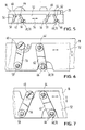
Das in Fig. 1 schematisch dargestellte Druckwerk 2 ist in einem Druckergehäuse 4 angeordnet. Es umfaßt einen Druckkopf 6, einen als Druckgegenlager dienenden Druckbalken 8, eine oder mehrere nebeneinanderliegende Transportrollen 10 zum Weitertransportieren des Aufzeichnungsträgers 12 in Richtung des Pfeiles 14 und als Gegenlager für die Transportrollen 10 dienende Gegenrollen 16. Der Druckbalken 8 und die Transportrollen 10 sind auf einem Träger 18 angeordnet, welcher in Richtung des Pfeiles 20 verstellbar im Druckergehäuse 4 gelagert ist. Die zur Lagerung und Verstellung des Trägers 18 in Richtung des Pfeiles 20 vorgesehenen Mittel werden weiter hinten beschrieben.The
Wie Fig. 1 erkennen läßt, ist die Transportrollenachse 22 nicht direkt auf dem Träger 18 gelagert, sondern auf einem Übersetzungshebel 24, welcher seinerseits um die Achse 26 schwenkbar am Träger 18 gelagert ist. Auf diese Weise kann sich die Transportrollenachse 22 auf einem Bogen um die Achse 26, d. h. also im wesentlichen in einer der Verstellrichtung 20 des Trägers 18 entsprechenden Richtung relativ zum Träger 18 verschieben. Das freie Ende des Übersetzungshebels 24 ist von einer Andruckfeder 28 beaufschlagt, welche dieses Ende in Andruckrichtung, d. h. also in Richtung des Pfeiles 30 belastet.As can be seen in FIG. 1, the
Fest im Träger 18 angeordnet ist ein Grenzschalter 32 mit drei Kontaktlamellen 34, 35, 36; die mittlere Kontaktlamelle 35 kann durch einen am Übersetzungshebel 24 ausgebildeten Betätigungsvorsprung 38 aus einer in Fig. 1 dargestellten oberen Schaltstellung über eine Neutralstellung in eine in Fig. 2 dargestellte untere Schaltstellung bewegt werden. Die obere Schaltstellung gemäß Fig. 1 bewirkt eine Aktivierung des Verstellantriebes für den Träger 18 in Andruckrichtung 30, die untere Schaltstellung gemäß Fig. 2 eine Aktivierung in der Gegenrichtung; in der dazwischenliegenden Neutralstellung ist der Verstellantrieb nicht aktiviert.A
Die Funktion des Druckwerkes wird im folgenden anhand der Fig. 1 und 2 erläutert. Bei der in Fig. 1 dargestellten abgesenkten Stellung des Trägers 18 befindet sich das Druckwerk in einem für das Einlegen des Aufzeichnungsträgers 12 bereiten Zustand. Der Aufzeichnungsträger 12 wird zwischen dem Druckkopf 6 und dem Druckbalken 8 eingeführt, bis er an einem Anschlag 40 anliegt. Ein geeigneter Sensor stellt fest, daß ein Aufzeichnungsträger 12 eingelegt wurde und aktiviert den Verstellantrieb für den Träger 18. Da der Grenzschalter 32 eine Schaltstellung aufweist, welche einer Betätigung des Verstellantriebes im Sinne einer Zustellung des Trägers 18 in Richtung des Pfeiles 30 entspricht, bewegt sich der Träger 18 nach oben und legt den Aufzeichnungsträger 12 gegen die Gegenrollen 16 an. Bei einer Weiterbewegung des Trägers 18 in Richtung des Pfeiles 30 wird die Transportrollenachse 22 relativ zum Träger 18 gegen die Kraft der Andruckfeder 28 nach unten verschoben. Bei einer vorbestimmten Zusammendrückung der Andruckfeder 28, bei der diese die gewünschte Andruckkraft aufbringt, wird die Kontaktlamelle 35 durch den Betätigungsfortsatz 38 von der Kontaktlamelle 34 abgehoben, so daß der Verstellantrieb stehen bleibt. Bei dieser Stellung, bei der die erwünschte Andruckkraft der Transportrollen erreicht wird, hat der Druckbalken 8 gleichzeitig seinen korrekten Schreibabstand zum Druckkopf 6, so daß das Druckwerk schreibbereit ist.The function of the printing unit is explained below with reference to FIGS. 1 and 2. The one shown in Fig. 1 When the
Gleichzeitig mit Erreichen der Schreibbereitschaft werden in bekannter Weise der Transportantrieb für die Transportrollen 10 und der Druckkopf 6 aktiviert, so daß der Aufzeichnungsträger 12 z. B. zeilenweise beschrieben wird. Während der Zustellbewegung des Trägers 18 ist der Anschlag 40 aus seiner in Fig. 1 dargestellten Betriebsstellung in die in Fig. 2 dargestellte Außerbetriebsstellung bewegt worden, wie weiter hinten noch genauer erläutert wird.Simultaneously with the readiness to write, the transport drive for the
Die Transportrollen 10 erfüllen gleichzeitig die Aufgabe, die Stärke des Aufzeichnungsträgers 12 festzustellen und den Druckabstand zwischen dem Druckkopf 6 und dem Druckbalken 8 zu steuern. Wenn der Aufzeichnungsträger 12 z. B. eine mit zunehmender Einzugsbewegung abnehmende Stärke aufweist, wie das bei Kassenbelegen oder dergleichen häufig der Fall ist, dann verschieben sich die Transportrollen 10 bei Erreichen jeder Stufe relativ zum Träger 18 um einen der Stufenhöhe entsprechenden Betrag nach oben. Dabei hebt sich der Betätigungsfortsatz 38 von der mittleren Kontaktlamelle 35 ab, diese kommt in Kontakt mit der oberen Kontaktlamelle 34, so daß der Verstellantrieb des Trägers 18 diesen nach oben bewegt, bis der Grenzschalter 32 wieder seine Neutralstellung einnimmt. Wenn die Stärke des Beleges zunimmt, verschieben sich die Transportrollen 10 relativ zum Träger 18 entsprechend nach unten, wobei die mittlere und untere Kontaktlamelle 35 bzw. 36 in Kontakt kommen, so daß der Träger 18 nach unten verstellt wird, bis der Grenzschalter 32 wiederum seine Neutralstellung innehat, wobei gleichzeitig die Transportrolle 10 ihren korrekten Andruck, der Druckbalken 8 seinen korrekten Schreibabstand zum Druckkopf 6 aufweist.The
Die Fig. 3 und 4 zeigen das Druckwerk 2 schematisch in einer Schnittdarstellung, bei der der Anschlag 40 in seinen beiden möglichen Stellungen zu erkennen ist. Der Anschlag 40 besteht aus einer etwa senkrecht zur Schreibebene stehenden Anschlagplatte 42, die über einen dazu rechtwinklig stehenden Arm 44 um eine Achse 46 schwenkbar im Druckergehäuse 4 gelagert ist. Am Arm 44 greift eine Zugfeder 48 an, deren freies Ende an einem Befestigungspunkt 50 mit dem Träger 18 fest verbunden ist. Der Befestigungspunkt 50 befindet sich in der abgesenkten Stellung des Trägers 18 gemäß Fig. 3 etwas unterhalb der Achse 46, so daß der Anschlag 40 in seiner dargestellten Betriebsstellung gehalten wird. Wenn der Träger 18 in Richtung des Pfeiles 30 zugestellt wird, bewegt sich auch der Befestigungspunkt 50 nach oben, so daß bei Überschreiten eines bestimmten Totpunktes der Anschlag 40 nach links gekippt wird, wobei die Anschlagplatte 42 sich aus der durch den Aufzeichnungsträger 12 definierten Schreibebene zurückzieht und den Weitertransport des Aufzeichnungsträgers ermöglicht. Beim Absenken des Trägers 18 schnappt der Anschlag 40 wieder in seine Betriebsstellung.3 and 4 show the
Die in Richtung des Pfeiles 20 verstellbare Lagerung des Trägers 18 erfolgt über eine Parallellenker-Anordnung gemäß Fig. 5. Parallel zu zwei Längsseiten des Trägers 18 ist je ein Verstellriegel 52 in Richtungs des Pfeiles 54 verschiebbar gelagert und mit einem nicht dargestellten Verstellantrieb verbunden. In Fig. 5 ist nur der dem Betrachter zugekehrte Verstellriegel 52 dargestellt. Zwei Lenkerarme 56 sind in Drehpunkten 58 schwenkbar mit dem Verstellriegel 52 verbunden. Die anderen Enden der Lenkerarme 56 sind in Drehpunkten 60 mit dem Träger 18 schwenkbar verbunden. Zwei weitere Lenkerarme 62 sind in Drehpunkten 64 mit dem Verstellriegel 52 schwenkbar verbunden. Die anderen Enden der Lenkerarme 62 sind mit den Drehpunkten 66 schwenkbar und senkrecht verschiebbar im Druckergehäuse und im Träger 18 in entsprechenden, sich deckenden Führungsschlitzen 68, 70 geführt. Bei einer Verstellung des Verstellriegels 52 nach rechts (in Fig. 5) wird der Träger 18 nach oben, bei einer Bewegung des Verstellriegels 52 nach links entsprechend nach unten verstellt.The mounting of the
Die Funktionsweise der Parallellenker-Anordnung ist anhand der Fig. 6 und 7 genauer erläutert. In Fig. 7 sind die beiden Lenkerarme 56 und 62 in einer Stellung dargestellt, die der Stellung gemäß Fig. 5 entspricht. Der Träger 18 befindet sich in seiner unteren Lage, bei der die Transportrollen außer Eingriff, der Druckbalken vom Druckkopf entfernt ist. Bei einer Bewegung des Verstellriegels 52 nach rechts (in Fig. 7) werden die mit dem Verstellriegel 52 fest verbundenen Drehpunkte 58, 64 in die in Fig. 6 dargestellten Lagen 58', 64' verschoben.The operation of the parallel link arrangement is explained in more detail with reference to FIGS. 6 and 7. In Fig. 7, the two
Da der Drehpunkt 58 in senkrechter Richtung nicht ausweichen kann, wird der Drehpunkt 60 um den Betrag a nach oben verschoben, wobei er den mit den Drehpunkt 60 fest verbundenen Träger 18 mitnimmt. Der im Druckergehäuse ausgebildete Schlitz 68 erlaubt nur eine senkrechte Verschiebung des Drehpunktes 66. Da der Träger 18 über den in diesem ausgebildeten Schlitz 70 gegenüber dem Drehpunkt 66 ebenfalls nur eine senkrechte Bewegung ausführen kann, wird der Träger 18 ohne Seitenbewegung senkrecht nach oben angehoben.Since the fulcrum 58 cannot deflect in the vertical direction, the
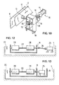
Fig. 8 zeigt wiederum das Druckwerk 2 mit dem Druckergehäuse 4, dem darin in Richtung des Pfeiles 20 verstellbaren Träger 18, den auf dem Träger angeordneten Transportrollen 10 sowie dem Druckbalken 8, ferner mit dem Druckkopf 6 und den Gegenrollen 16. Außerdem ist der dem Betrachter zugekehrte, horizontal verschiebbare Verstellriegel 52 erkennbar. Die horizontale Verstellung des Verstellriegels 52 erfolgt über einen in diesen eingreifenden Mitnehmer 72 (s. Fig. 8 und 9), welcher in eine im Verstellriegel 52 ausgebildete Ausnehmung 74 eingreift.Fig. 8 again shows the
Fig. 9 zeigt einen Verstellantrieb 76, welcher als sogenannter Positionierantrieb ausgebildet ist. Er umfaßt einen Elektromotor 78, welcher in beiden Drehrichtungen laufen kann und eine Gewindespindel 80 antreibt. Auf der Gewindespindel 80 ist eine Spindelmutter 82 angeordnet, welche von der Gewindespindel 80 in Richtung des Pfeiles 84 verstellbar ist. Die Spindelmutter 82 ist mit dem Mitnehmer 72 verbunden. Der Verstellantrieb 76 findet im Zusammenhang mit der in den Fig. 1 und 2 beschriebenen Anordnung der Transportrollen 10 Verwendung. Er wird durch den Grenzschalter 32 in der vorne beschriebenen Weise angesteuert, so daß der Träger 18 je nach Drehrichtung des Elektromotors 78 gehoben oder abgesenkt wird.9 shows an
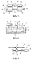
Fig. 10 zeigt einen Verstellantrieb 86, welcher als linearer Verstellantrieb mit zwei Schaltstellungen ausgebildet ist. Er umfaßt im wesentlichen einen im dargestellten Ausführungsbeispiels als U-förmiger Bügel ausgebildeten einarmigen Hebel 88, welcher mit seinem unteren Ende um die Achse 90 schwenkbar im Druckergehäuse gelagert ist. Der Hebel 88 trägt den Mitnehmer 72, welcher den Verstellriegel 52 in Richtung des Pfeiles 92 verstellt. Der Hebel 88 wird durch einen Magnetschalter 94 in zwei Schaltstellungen verschwenkt, die der Außereingriffsstellung bzw. der Eingriffsstellung der Transportrollen entsprechen. Das Betätigungsglied 96 ist mit einem U-förmigen Bügel 98 verbunden, welcher in Schaltrichtung des Magnetschalters 94 verschiebbar auf einer am Hebel 88 angeordneten Querachse 100 geführt ist. Zwischen dem Basisschenkel des Bügels 98 und der Achse 100 ist eine Druckfeder 102 angeordnet. Wenn der Magnetschalter 94 anzieht, nimmt er über den Bügel 98 den Hebel 88 mit und betätigt auf diese Weise den Verstellriegel 52 und den Träger 18 bis zur Anlage der Transportrollen an der Gegenrolle 16 bzw. dem dazwischen angeordneten Aufzeichnungsträger 12. Bei der weiteren Anzugsbewegung des Betätidungsgliedes 96 wird die Zwischenfeder 102 gespannt und bestimmt mit ihrer Federkraft die Andruckkraft der Transportrollen. Die Rückstellung erfolgt beispielsweise durch eine an geeigneter Stelle, beispielsweise am Verstellriegel 52 angreifende Rückstellfeder, wie nicht näher dargestellt wurde.10 shows an
Fig. 11 zeigt schematisch die Anordnung von zwei auf einer Transportrollenachse 122 angeordneten Transportrollen 110. Die Transportrollenachse ist beispielsweise, wie anhand der Fig. 1 und 2 beschrieben, mit einem Ende 104 ortsfest, jedoch schwenkbar im Druckergehäuse gelagert, während das andere Ende 106 in Richtung des Pfeiles 108 gegen die Kraft einer Andruckfeder 128 verschiebbar gelagert ist. Die Gegenrollen 116 sind auf einem gemeinsamen Pendeljoch 112 angeordnet, welches um eine Pendelachse 114 in der Schwenkebene der Transportrollenachse 122 ebenfalls schwenkbar ist. Auf diese Weise stellt sich immmer eine gleichmäßige Andruckkraft beider Transportrollen 110 auf den gegen die Gegenrollen 116 anliegenden Aufzeichnungsträger 12 ein, da sich das Pendeljoch 112 der jeweiligen Schwenkwinkelstellung der Transportrollenachse anpaßt.11 schematically shows the arrangement of two transport rollers arranged on a
Fig. 12 zeigt schematisch den Träger 18 mit auf diesem angeordneten Transportrollen 210. Die Transportrollenachse 222 ist im Träger 18 gelagert und mit diesem in Richtung des Pfeiles 212 verstellbar. Der Antriebsmotor 214 ist im Druckgehäuse 4 fest angeordnet. Zwischen dem Antriebsmotor 214 und der Transportrollenachse 222 ist eine Gelenkwelle 216 vorgesehen, welche die Höhenverstellung des Trägers 18 bei bestehender Antriebsverbindung ermöglicht.12 schematically shows the
Fig. 13 zeigt einen Träger 18, auf welchem eine Transportrollenachse 322 mit zwei Transportrollen 310 angeordnet ist. Der Träger ist wiederum in Richtung des Pfeiles 312 verstellbar im Druckergehäuse 4 gelagert. Im vorliegenden Ausführungsbeispiel ist der Antriebsmotor 314 ebenfalls auf dem Träger 18 angeordnet und wird mit diesem verstellt. Die Antriebsverbindung zwischen dem Antriebsmotor 314 und der Transportrollenachse 322 kann dementsprechend starr ausgebildet sein.13 shows a
Die Einrichtung zur Regelung des Andruckes der Transportrollen an den Gegenrollen, wie sie vorstehend beschrieben wurde, kann auch zur Regelung für den Andruck des Druckträgers gegen eine Thermoschreibleiste verwendet werden.The device for regulating the pressure of the transport rollers on the counter rollers, as described above, can also be used for regulating the pressure of the print carrier against a thermal writing strip.
Claims (9)
- A line printing unit, comprising a printing abutment (8) and at least one transport roller (10) which are disposed beneath a printing medium plane on a common carrier (18) adjustable relatively to the printing medium plane, and comprising a print head (6) co-operating with the printing abutment (8) and a backing roller (16) co-operating with the transport roller, which print head and backing roller are fixed above the printing medium plane, the transport roller (10) being disposed on the carrier (18) on a spindle (22) which is mounted for displacement in a direction corresponding substantially to the direction of displacement of the carrier (18) and which is loaded by a biasing spring (28) in the blasing direction, characterised in that the printing abutment (8) is fixed on the carrier (18) and in that a limit switch (32) adapted to be actuated by the displaceable transport roller spindle (22) is disposed on the carrier (18) and so controls a positioning drive (76) connected to the carrier (18) that after the transport roller (10) has engaged the backing roller (16) the transport roller spindle (22) occupies relatively to the carrier (18) a set position in which the biasing spring (28) has a specific compression.
- A printing unit according to claim 1, characterised in that the displaceable transport roller spindle (22) is mounted on a transmission lever (24) which is pivotally mounted on the carrier (18) and which increases the displacement movement of the transport roller spindle (22), the transmission lever drive end actuating the limit switch (32) and being subjected to the action of the blasing spring (28).
- A printing unit according to claim 1 or 2, characterised in that only one end (106) of the transport roller spindle (122) is mounted to be displaceable while the other end (104) is mounted to be stationary but pivotally on the carrier (18), in that the transport roller spindle (122) carries two spaced transport rollers (110) which co-operate with two respectively associated backing rollers (116) disposed on a common pendulum yoke (112) mounted to pivot in the pivot plane of the transport roller spindle (122) about a pendulum axis (114) disposed between the backing rollers (116).
- A line printing unit, comprising a printing abutment and at least one transport roller (10) which are disposed beneath a printing medium plane on a common carrier (18) adjustable relatively to the printing medium plane, and comprising a print head co-operating with the printing abutment and a backing roller (18) co-operating with the transport roller (10), which print head and backing roller are fixed above the printing medium plane, the transport roller (10) being fixed on the carrier (18) and a resilient transmission means (98, 100, 102) being disposed between the carrier and an adjustment drive (94) for the carrier (18), and the printing abutment (8) being fixed on the carrier (18) and the adjustment of the printing abutment (8) relatively to the transport roller (10) being so selected that when the transport roller (10) engages the backing roller or a printing medium (12) disposed between them a predetermined distance is left between the print head and the printing abutment (8) or the printing medium (12).
- A printing unit according to claim 4, characterised in that the resillient transmission means comprises a one-arm lever (88) which is mounted by one end pivotally in the printer housing and on which the adjustment member (96) of the adjustment drive (86) acts via an intermediate spring.
- A printing unit according to any one of claims 1 to 5, characterised in that the carrier (18) is in the form of a frame which is mounted on the printer housing (4) so as to be adjustable by way of a parallel link arrangement (65, 62).
- A printing unit according to any one of claims 1 to 6, characterised in that the printer housing (4) contains a stop (40) which is substantially perpendicular to the printing plane, extends in the line direction, and is mounted adjustably between an operative position projecting into the path of the printing medium (12) and a withdrawn inoperative position, and in that the stop (40) is so drivingly connected to the carrier that during the adjustment movement of the carrier (18) in the biasing direction the stop (40) moves into its inoperative position, while on the adjustment movement in opposition to the biasing direction it passes into its operative position.
- A printing unit according to any one of claims 2 to 7, characterised in that the transport roller (10) disposed on the carrier (18) is connected to a transport drive (314), the latter being rigidly drivingly connected on the carrier (18).
- A printing unit according to any one of claims 2 to 7, characterised in that the transport roller (10) disposed on the carrier (18) is connected to a transport drive (314), the latter being disposed in the printer housing (4) and being connected to the transport roller (210) via a cardan shaft (216).
Applications Claiming Priority (2)
| Application Number | Priority Date | Filing Date | Title |
|---|---|---|---|
| DE19853511387 DE3511387A1 (en) | 1985-03-28 | 1985-03-28 | PRINTING UNIT WITH A PRINT HEAD, WHICH CAN BE MOVED IN THE PRINTING LINE DIRECTION, AND A PRINT BAR PRESENTING AS A PRESSURE COUNTER |
| DE3511387 | 1985-03-28 |
Publications (3)
| Publication Number | Publication Date |
|---|---|
| EP0195981A2 EP0195981A2 (en) | 1986-10-01 |
| EP0195981A3 EP0195981A3 (en) | 1987-08-26 |
| EP0195981B1 true EP0195981B1 (en) | 1991-12-11 |
Family
ID=6266645
Family Applications (1)
| Application Number | Title | Priority Date | Filing Date |
|---|---|---|---|
| EP86103352A Expired - Lifetime EP0195981B1 (en) | 1985-03-28 | 1986-03-12 | Printing mechanism with a printing head movable in print line direction and a print hammer bar as platen backing |
Country Status (3)
| Country | Link |
|---|---|
| EP (1) | EP0195981B1 (en) |
| JP (1) | JPH0721332Y2 (en) |
| DE (2) | DE3511387A1 (en) |
Families Citing this family (13)
| Publication number | Priority date | Publication date | Assignee | Title |
|---|---|---|---|---|
| JPH0729452B2 (en) * | 1985-10-25 | 1995-04-05 | 株式会社日立製作所 | Printer |
| DE8703083U1 (en) * | 1987-02-27 | 1987-06-11 | Nixdorf Computer Ag, 4790 Paderborn, De | |
| GB8722622D0 (en) * | 1987-09-25 | 1987-11-04 | Halo Retail Systems Ltd | Dot-matrix printers |
| US5087135A (en) * | 1988-04-14 | 1992-02-11 | Dataproducts Corporation | Printer paper thickness detector |
| US4957382A (en) * | 1989-12-06 | 1990-09-18 | Ncr Corporation | Platen-yoke apparatus for a printer using a floating platen |
| DE4014124A1 (en) * | 1990-05-02 | 1991-11-07 | Esselte Meto Int Gmbh | Thermographic printing device for price tickets etc. - has printing head supported for movement relative to counter pressure roller |
| JP2541457Y2 (en) * | 1990-08-31 | 1997-07-16 | アマノ株式会社 | Printing device |
| DE4228765C2 (en) * | 1992-08-28 | 1998-04-09 | Francotyp Postalia Gmbh | Pressure device for a franking machine with an electrothermal printing device |
| US5648811A (en) * | 1992-08-28 | 1997-07-15 | Francotyp-Postalia Aktiengesellschaft & Co. | Postage meter |
| GB9226781D0 (en) * | 1992-12-23 | 1993-02-17 | Neopost Ltd | Thermal printing apparatus |
| IT1276494B1 (en) * | 1995-07-12 | 1997-10-31 | Olivetti & Co Spa | IMPACT PRINTER WITH SIGNABLE CONTRAST BAR |
| JP3841315B2 (en) * | 1995-12-26 | 2006-11-01 | キヤノン株式会社 | Printing apparatus and printing method used in the apparatus |
| CN1313281C (en) * | 2003-11-04 | 2007-05-02 | 精工爱普生株式会社 | Recorder |
Family Cites Families (17)
| Publication number | Priority date | Publication date | Assignee | Title |
|---|---|---|---|---|
| DE2248262C3 (en) * | 1972-10-02 | 1978-12-21 | Walther-Bueromaschinen Gmbh, 7921 Gerstetten | Automatic material thickness sensing device for the recording medium for high-speed printing units in office machines |
| US3837461A (en) * | 1973-03-13 | 1974-09-24 | Singer Co | Print station for a matrix printer |
| IT1021169B (en) * | 1973-09-27 | 1978-01-30 | Sperry Rand Corp | METHOD AND DEVICE FOR AUTOMATICALLY ADJUSTING THE PRINT SPACE OF A PRINTER |
| IT1020820B (en) * | 1974-09-18 | 1977-12-30 | Olivetti & Co Spa | DEVICE FOR AUTOMATIC FEEDING OF DOCUMENTS FOR ACCOUNTING MACHINES OR SIMILAR |
| US3995730A (en) * | 1975-03-31 | 1976-12-07 | Bunker Ramo Corporation | Dot matrix impact printer having retractable platen |
| DE2608301C2 (en) * | 1976-02-28 | 1986-02-20 | Ncr Corp., Dayton, Ohio | Device for regulating the distance between a print head and a recording medium |
| DE2651884C3 (en) * | 1976-11-13 | 1981-05-14 | Philips Patentverwaltung Gmbh, 2000 Hamburg | Device for electromechanical distance control of a print head from the platen |
| US4227819A (en) * | 1978-11-24 | 1980-10-14 | International Computers Limited | Printer platen |
| IT1122891B (en) * | 1979-08-30 | 1986-04-30 | Honeywell Inf Systems Italia | DRIVE DEVICE FOR PRINTING SUPPORT |
| JPS56104950U (en) * | 1980-01-16 | 1981-08-15 | ||
| JPS56123252U (en) * | 1980-02-20 | 1981-09-19 | ||
| US4422782A (en) * | 1982-06-28 | 1983-12-27 | Ncr Corporation | Record member feed and support mechanism |
| JPS5935056U (en) * | 1982-08-31 | 1984-03-05 | 富士通株式会社 | Platen evacuation mechanism |
| JPS5950751U (en) * | 1982-09-27 | 1984-04-04 | ユ−ザツク電子工業株式会社 | printer device |
| JPS59181756U (en) * | 1983-05-24 | 1984-12-04 | ブラザー工業株式会社 | slip printer |
| JPS60152U (en) * | 1983-06-17 | 1985-01-05 | 日本電気株式会社 | Printing device platen retraction mechanism |
| US4575267A (en) * | 1984-04-23 | 1986-03-11 | Ncr Corporation | Record media thickness compensating mechanism |
-
1985
- 1985-03-28 DE DE19853511387 patent/DE3511387A1/en not_active Ceased
-
1986
- 1986-03-12 EP EP86103352A patent/EP0195981B1/en not_active Expired - Lifetime
- 1986-03-12 DE DE8686103352T patent/DE3682796D1/en not_active Expired - Fee Related
- 1986-03-28 JP JP1986046019U patent/JPH0721332Y2/en not_active Expired - Lifetime
Also Published As
| Publication number | Publication date |
|---|---|
| EP0195981A3 (en) | 1987-08-26 |
| DE3682796D1 (en) | 1992-01-23 |
| EP0195981A2 (en) | 1986-10-01 |
| DE3511387A1 (en) | 1986-10-16 |
| JPS61166852U (en) | 1986-10-16 |
| JPH0721332Y2 (en) | 1995-05-17 |
Similar Documents
| Publication | Publication Date | Title |
|---|---|---|
| DE2535136C2 (en) | Holding device in a printing device for holding a single sheet or a recording medium having a book spine | |
| EP0195981B1 (en) | Printing mechanism with a printing head movable in print line direction and a print hammer bar as platen backing | |
| EP0196580B1 (en) | Apparatus for cutting form webs | |
| EP0052408B1 (en) | Printing mechanism with a recording element and means for the rotation of a record carrier | |
| DE4041985A1 (en) | PRINTER, IN PARTICULAR MATRIX PRINTER | |
| DE2752061C3 (en) | Device for adjusting the distance of a print head perpendicular to the platen | |
| DE2651884A1 (en) | DEVICE FOR ELECTROMECHANICAL DISTANCE REGULATION OF A PRINT HEAD FROM THE PRINTING PLATE | |
| EP0021388A1 (en) | Apparatus for cutting vertical paper webs | |
| DE2829827A1 (en) | GUIDE DEVICE FOR RECORDING CARRIERS AT PRINTING WORKS | |
| DE1292672B (en) | Device for conveying writing sheets in writing or similar machines | |
| DE3636814C2 (en) | ||
| EP0884699B1 (en) | Franking machine | |
| EP0530583A1 (en) | Sheet feeder | |
| EP0079008A2 (en) | Feeding device for single or multiple sheets | |
| DE602004005621T2 (en) | Device for adjusting the angular position of print heads | |
| DE3204348C2 (en) | Paper feed for printer | |
| DE2704267C2 (en) | Control device with a main lever pivotably mounted on a pivot axis | |
| DE3140473A1 (en) | "PRINTING DEVICE WITH DRIVE ENGINE AND A WRITER" | |
| DE1221649B (en) | Write head for mosaic printer whose recording medium is moistened | |
| DE2110171A1 (en) | Height position measurement for printing material from a strip printer | |
| EP0064668B1 (en) | Pivot for a printing mechanism | |
| DE102004038753B3 (en) | Singling system for stack of sheets of paper has rollers with patterned surfaces mounted on shaft on end of arm with hinge at either end | |
| DE3630782A1 (en) | Printing mechanism with endless paper and single-sheet conveyance | |
| DE2549004B2 (en) | Device for setting the type wheels of a rotating printing cylinder | |
| EP0190629A2 (en) | Severing device for form webs or single sheets in office machines, in particular matrix printers |
Legal Events
| Date | Code | Title | Description |
|---|---|---|---|
| PUAI | Public reference made under article 153(3) epc to a published international application that has entered the european phase |
Free format text: ORIGINAL CODE: 0009012 |
|
| AK | Designated contracting states |
Kind code of ref document: A2 Designated state(s): AT BE CH DE FR GB IT LI LU NL SE |
|
| PUAL | Search report despatched |
Free format text: ORIGINAL CODE: 0009013 |
|
| RHK1 | Main classification (correction) |
Ipc: B41J 11/20 |
|
| AK | Designated contracting states |
Kind code of ref document: A3 Designated state(s): AT BE CH DE FR GB IT LI LU NL SE |
|
| 17P | Request for examination filed |
Effective date: 19880224 |
|
| RBV | Designated contracting states (corrected) |
Designated state(s): DE FR GB IT NL SE |
|
| 17Q | First examination report despatched |
Effective date: 19890512 |
|
| RIN1 | Information on inventor provided before grant (corrected) |
Inventor name: MALKE, WOLFGANG Inventor name: DOBRING, WILFRIED |
|
| RAP3 | Party data changed (applicant data changed or rights of an application transferred) |
Owner name: SIEMENS NIXDORF INFORMATIONSSYSTEME AKTIENGESELLSC |
|
| GRAA | (expected) grant |
Free format text: ORIGINAL CODE: 0009210 |
|
| AK | Designated contracting states |
Kind code of ref document: B1 Designated state(s): DE FR GB IT NL SE |
|
| REF | Corresponds to: |
Ref document number: 3682796 Country of ref document: DE Date of ref document: 19920123 |
|
| GBT | Gb: translation of ep patent filed (gb section 77(6)(a)/1977) | ||
| ET | Fr: translation filed | ||
| ITF | It: translation for a ep patent filed |
Owner name: MODIANO & ASSOCIATI S.R.L. |
|
| PGFP | Annual fee paid to national office [announced via postgrant information from national office to epo] |
Ref country code: NL Payment date: 19920331 Year of fee payment: 7 |
|
| PLBE | No opposition filed within time limit |
Free format text: ORIGINAL CODE: 0009261 |
|
| STAA | Information on the status of an ep patent application or granted ep patent |
Free format text: STATUS: NO OPPOSITION FILED WITHIN TIME LIMIT |
|
| 26N | No opposition filed | ||
| PG25 | Lapsed in a contracting state [announced via postgrant information from national office to epo] |
Ref country code: NL Effective date: 19931001 |
|
| NLV4 | Nl: lapsed or anulled due to non-payment of the annual fee | ||
| PGFP | Annual fee paid to national office [announced via postgrant information from national office to epo] |
Ref country code: SE Payment date: 19940324 Year of fee payment: 9 |
|
| EAL | Se: european patent in force in sweden |
Ref document number: 86103352.0 |
|
| PG25 | Lapsed in a contracting state [announced via postgrant information from national office to epo] |
Ref country code: SE Effective date: 19950313 |
|
| EUG | Se: european patent has lapsed |
Ref document number: 86103352.0 |
|
| PGFP | Annual fee paid to national office [announced via postgrant information from national office to epo] |
Ref country code: DE Payment date: 19960520 Year of fee payment: 11 |
|
| PGFP | Annual fee paid to national office [announced via postgrant information from national office to epo] |
Ref country code: GB Payment date: 19970224 Year of fee payment: 12 |
|
| PGFP | Annual fee paid to national office [announced via postgrant information from national office to epo] |
Ref country code: FR Payment date: 19970321 Year of fee payment: 12 |
|
| PG25 | Lapsed in a contracting state [announced via postgrant information from national office to epo] |
Ref country code: DE Effective date: 19971202 |
|
| PG25 | Lapsed in a contracting state [announced via postgrant information from national office to epo] |
Ref country code: GB Free format text: LAPSE BECAUSE OF NON-PAYMENT OF DUE FEES Effective date: 19980312 |
|
| PG25 | Lapsed in a contracting state [announced via postgrant information from national office to epo] |
Ref country code: FR Free format text: THE PATENT HAS BEEN ANNULLED BY A DECISION OF A NATIONAL AUTHORITY Effective date: 19980331 |
|
| GBPC | Gb: european patent ceased through non-payment of renewal fee |
Effective date: 19980312 |
|
| REG | Reference to a national code |
Ref country code: FR Ref legal event code: ST |
|
| PG25 | Lapsed in a contracting state [announced via postgrant information from national office to epo] |
Ref country code: IT Free format text: LAPSE BECAUSE OF NON-PAYMENT OF DUE FEES;WARNING: LAPSES OF ITALIAN PATENTS WITH EFFECTIVE DATE BEFORE 2007 MAY HAVE OCCURRED AT ANY TIME BEFORE 2007. THE CORRECT EFFECTIVE DATE MAY BE DIFFERENT FROM THE ONE RECORDED. Effective date: 20050312 |