EP0195572A2 - Papiereinführvorrichtung für Drucker - Google Patents
Papiereinführvorrichtung für Drucker Download PDFInfo
- Publication number
- EP0195572A2 EP0195572A2 EP86301680A EP86301680A EP0195572A2 EP 0195572 A2 EP0195572 A2 EP 0195572A2 EP 86301680 A EP86301680 A EP 86301680A EP 86301680 A EP86301680 A EP 86301680A EP 0195572 A2 EP0195572 A2 EP 0195572A2
- Authority
- EP
- European Patent Office
- Prior art keywords
- paper
- platen
- printing
- feed passage
- printer
- Prior art date
- Legal status (The legal status is an assumption and is not a legal conclusion. Google has not performed a legal analysis and makes no representation as to the accuracy of the status listed.)
- Granted
Links
Images


Classifications
-
- B—PERFORMING OPERATIONS; TRANSPORTING
- B41—PRINTING; LINING MACHINES; TYPEWRITERS; STAMPS
- B41J—TYPEWRITERS; SELECTIVE PRINTING MECHANISMS, i.e. MECHANISMS PRINTING OTHERWISE THAN FROM A FORME; CORRECTION OF TYPOGRAPHICAL ERRORS
- B41J13/00—Devices or arrangements of selective printing mechanisms, e.g. ink-jet printers or thermal printers, specially adapted for supporting or handling copy material in short lengths, e.g. sheets
- B41J13/10—Sheet holders, retainers, movable guides, or stationary guides
- B41J13/103—Sheet holders, retainers, movable guides, or stationary guides for the sheet feeding section
-
- B—PERFORMING OPERATIONS; TRANSPORTING
- B41—PRINTING; LINING MACHINES; TYPEWRITERS; STAMPS
- B41J—TYPEWRITERS; SELECTIVE PRINTING MECHANISMS, i.e. MECHANISMS PRINTING OTHERWISE THAN FROM A FORME; CORRECTION OF TYPOGRAPHICAL ERRORS
- B41J11/00—Devices or arrangements of selective printing mechanisms, e.g. ink-jet printers or thermal printers, for supporting or handling copy material in sheet or web form
- B41J11/48—Apparatus for condensed record, tally strip, or like work using two or more papers, or sets of papers, e.g. devices for switching over from handling of copy material in sheet form to handling of copy material in continuous form and vice versa or point-of-sale printers comprising means for printing on continuous copy material, e.g. journal for tills, and on single sheets, e.g. cheques or receipts
- B41J11/54—Apparatus for condensed record, tally strip, or like work using two or more papers, or sets of papers, e.g. devices for switching over from handling of copy material in sheet form to handling of copy material in continuous form and vice versa or point-of-sale printers comprising means for printing on continuous copy material, e.g. journal for tills, and on single sheets, e.g. cheques or receipts in which one paper or set is fed towards printing position from the front of the apparatus
Definitions
- the present invention relates to a printer capable of setting a second paper therein keeping a first paper in its set state and of printing any data on the newly set paper, and furthermore to a paper insertion apparatus suitable for the printer.
- a printer of this type is disclosed in, for example, Japanese Patent Application No. 58-31313 (priority declaration No. US 948860).
- the printer is capable of treating different types of documents such, for example, as receipt tapes, etc., for monetary transactions, scrips and multipart documents for relatively complicated business such as taxation and sales, etc.
- the apparatus has a first receipt tape feed passage for guiding a receipt tape delivered from a supply roll housed in the apparatus to a printing part, and a second scrip feed passage for guiding a scrip inserted by an operator from the front of the apparatus to the printing part.
- the apparatus can print data about monetary transactions on a receipt tape guided through the first receipt tape feed passage and put a scrip inserted from the outside on the receipt tape and print any data about taxation and sales, etc., on the scrip.
- the device can feed a paper between a pinch roller and a platen provided upward of the printing part, and with the paper pressed by the pinch roller, send the paper by rotation of the platen.
- the apparatus is made thicker by a space corresponding to a passage needed to insert the scrip. As a result, the apparatus is unsuitable for desktop use or it must have a hole made in a table for allowing the paper to pass therethrough.
- Another object of the present invention is to provide a paper insertion device capable of placing a second paper thereon with accurate positioning of the paper and guiding the paper to the second feed passage.
- Still another object of the present invention is to provide a printer provided with a paper insertion device, the printer being made thinner upon employing a paper of one kind, and being capable of simultaneously setting two types of papers and printing any data on the upper paper.
- a printer has a first paper feed passage extending from the back of a platen through the lower portion thereof to a printing portion, and a second paper feed passage extending from a portion substantially Directly below the printing portion almost to the printing portion.
- the printer includes a first pinch roller disposed on the way- to the first paper feed passage for bringing a first paper into close contact with the platen, the first paper being fed by rotation of the platen, and further includes a second pinch roller on the way to the second paper feed passage for pressing a second paper against the platen, the second paper being fed by rotation of the platen.
- a paper insertion device has a flat section for placing a paper thereon as well as a slit for changing the advance direction of the paper from horizontal to vertical.
- the paper goes upward along the curved surface of the slit and enters the second paper feed passage with ease for further advance.
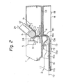
- a printer As shown in Fig. 1, a printer according to the present invention comprises a printing unit 1 and a paper insertion unit 2, and for them in use the paper insertion unit is placed on a desk, and the printing unit 1 placed thereon.
- Fig. 2 illustrating, in a side cross-sectional view, of the printer in use, details of the printer are neglected for brevity.
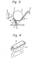
- Two types of papers are allowed to advance in the direction of an arrow shown in Fig. 3.
- the printer has an opening 3 formed in the central lower part of the printing unit 1., and an opening 4 corresponding to the opening 3 and formed in the central upper part of the paper insertion unit 2.
- the opening 3 facing to the opening 4 partly forms a paper feed passage.
- the printing unit 1 includes a printing head 5, a platen 6, pinch rollers 7, 8, paper guides 9, 10, 11, and a tractor 21.
- the paper guide 9 extends from the platen 6 to the lower part thereof, and further along the outer peripheral surface of the platen 6 to the front thereof, and forms a first paper feed passage through which a continuous paper 12 passes, jointly with the platen 6.
- the pinch roller 7 is located on the way to the first paper feed passage, and presses the continuous paper 12 against the platen 6 at a position backward from just under the platen.
- the paper guides 10, 11 extend from the opening 3 to a position where a printing head 5 and the platen 6 face to each other, i.e., to a printing position upward, and the pinch roller 8 located on the way to a second paper feed passage for pressing a scrip 13 against the platen 6 between the tips of-the paper guides 10, 11 and the printing position.
- the paper insertion unit 2 includes a frame 14 for supporting the printing unit 1, a upper guide plate 15, a lower guide plate 16, and a side guide 17.
- the frame 14 has guide holes 18 to permit support legs of the printing unit 1 to be inserted in the upper four corners thereof, and rubber-made legs 19 are mounted on the bottom at positions substantially corresponding to the four corners.
- the upper guide plate 15 has a upper wall 15a suspended from the upper surface of the frame 14 and a crook part 1 5b extending upward from the lowest position of the upper wall 15a.
- the lower guide plate 16 has a flat part 16a for supporting a scrip 1 3 and a crook part 1 6b extending upward from the rear of the flat part.
- the side guide plate 17 is mounted on the front end of the lower guide plate 16 by making use of a _flexing edge 17a itself and supported movably widthwise of a paper.
- a slit 20 is formed by the crook part 15b of the upper guide plate 1 5 and the crook part 1 6b of the lower guide plate 16, and the scrip 13 is guided to the opening 3 of the printing unit 1 through the slit 20.
- a continuous paper 12 is typically employed in the embodiment with the above arrangement according to the present invention.
- the continuous paper 12 is intermittently fed by a tractor 21 inserted from the rear of the printing unit 1 and allowed to advance on the first paper feed passage.
- the continuous paper is printed thereon with prescribed data at a prescribed position, and again fed by means of the tractor 21 after completing the printing along one line of the paper.
- a scrip 13 is placed on the flat part 16a of the lower guide plate 16 and forced to advance along the side guide 17.
- ⁇ A scrip 13 of a different size may also be employed or may be transversely displaced in its set position at need by moving the side guide 17.
- the scrip 13 runs on in its tip on the crook part 16b of the lower guide plate 16, and guided to the slit 20 while pressed down in its floating by the upper guide plate 15.
- the scrip is further forced to advance through the slit 20, the opening 4 in the paper insertion unit 2, and the opening 3 in the printing unit 1, and further forced to pass through between the paper guides 10, 11, i.e., through the second feed passage and strikes a contact part 24 between the pinch roller 8 and the platen 6.
- the platen 6 is rotated with this state.
- the scrip 13 is forced to advance upward together with the continuous paper 12 following rotation of the platen 6 while being pressed against the platen 6 by means of the pinch roller 8.
- the scrip 13 has then been put on the continuous paper 12. After stopping the rotation of the platen 6 at a proper position, printing is started.
- the platen 6 is rotated to force the scrip 13 and the continuous paper 12 to be again advanced. After printing necessary data in such a way, the platen 6 is further rotated to force the scrip 13 to a position where it is put out of the contact with the pinch roller 8. With this operation, the scrip 13 is discharged. Thereafter, the next scrip may be inserted or printed thereon if necessary, or the continuous paper 12 may be printed thereon. ⁇
- the continuous paper 12 is also advanced in conformity with the rotation of the platen 6, but there is no sag on the continuous paper 12 since the paper tractor 21 is driven in synchronism with the platen 6.
- This is achieved by mounting a gear on a shaft of the platen 6 and rotating the shaft of the tractor 21 via a gear engaging with the above gear.
- the pinch roller 6 is supported by a frame 22 formed by a spring and shaped as shown in Fig. 4 and thereby the pinch roller 8 is endowed with the press force to the platen 6.
- the frame 22 is mounted on a beam 23 of Fig. 1.
- the printer according to the present invention was given as being typically capable of printing any data on a scrip or a continuous paper at need, it is also possible to permit the continuous paper 12a to be inserted therein from the paper insertion unit 2 and the paper to be advanced by means of the tractor 21. There is no fear perforations in a continuous paper before printing is caught by those in the same paper after the printing and thereby the latter paper is again drawn into the paper feed passage, since the continuous paper 12 does not take a U-turn in this case.
- first and second paper feed passages also in the vicinity of the sprocket wheel 25 facilitates setting of any paper.
- an integral guide frame 26 is mounted on the shaft of the platen as shown in Fig. 7.
- the guide frame 26 has a main guide 26a, a sub-guide 26b, and a side plate 26c, and an opening 26d is formed in a gap between the main guide 26a and the sub-guide 26b.
- a slit 20a may be formed by forming the upper guide part 28 having a proper width on the tip of the side guide 27 as shown in Fig. 8 and making use of a crook part 28a of the upper guide part 28 and a crook part 16b of the lower guide plate 16.
Landscapes
- Handling Of Sheets (AREA)
- Handling Of Continuous Sheets Of Paper (AREA)
Applications Claiming Priority (4)
| Application Number | Priority Date | Filing Date | Title |
|---|---|---|---|
| JP3286485U JPS61150154U (de) | 1985-03-09 | 1985-03-09 | |
| JP32864/85U | 1985-03-09 | ||
| JP3286385U JPS61150153U (de) | 1985-03-09 | 1985-03-09 | |
| JP32863/85U | 1985-03-09 |
Related Child Applications (1)
| Application Number | Title | Priority Date | Filing Date |
|---|---|---|---|
| EP90111638.4 Division-Into | 1986-03-10 |
Publications (3)
| Publication Number | Publication Date |
|---|---|
| EP0195572A2 true EP0195572A2 (de) | 1986-09-24 |
| EP0195572A3 EP0195572A3 (en) | 1987-08-19 |
| EP0195572B1 EP0195572B1 (de) | 1990-12-27 |
Family
ID=26371453
Family Applications (2)
| Application Number | Title | Priority Date | Filing Date |
|---|---|---|---|
| EP90111638A Withdrawn EP0404096A1 (de) | 1985-03-09 | 1986-03-10 | Papiereinführvorrichtung für Drucker |
| EP86301680A Expired EP0195572B1 (de) | 1985-03-09 | 1986-03-10 | Papiereinführvorrichtung für Drucker |
Family Applications Before (1)
| Application Number | Title | Priority Date | Filing Date |
|---|---|---|---|
| EP90111638A Withdrawn EP0404096A1 (de) | 1985-03-09 | 1986-03-10 | Papiereinführvorrichtung für Drucker |
Country Status (3)
| Country | Link |
|---|---|
| US (2) | US4722623A (de) |
| EP (2) | EP0404096A1 (de) |
| DE (1) | DE3676523D1 (de) |
Cited By (2)
| Publication number | Priority date | Publication date | Assignee | Title |
|---|---|---|---|---|
| EP0265418A2 (de) * | 1986-10-13 | 1988-04-27 | Rudolf Dipl.-Ing. Svoboda | Papierbahnführung für Drucker |
| US5988904A (en) * | 1997-09-02 | 1999-11-23 | Hewlett-Packard Company | Removable rollfeed apparatus for a desk-mountable printer |
Families Citing this family (8)
| Publication number | Priority date | Publication date | Assignee | Title |
|---|---|---|---|---|
| GB2196300B (en) * | 1986-10-18 | 1991-04-03 | Sony Corp | Printing apparatus |
| SE500298C2 (sv) * | 1989-02-27 | 1994-05-30 | Bjoern Jondelius | Låda för uppbärande av skrivare till en dator |
| JPH0393577A (ja) * | 1989-09-06 | 1991-04-18 | Tokyo Electric Co Ltd | プリンタ |
| JP2984066B2 (ja) * | 1991-01-29 | 1999-11-29 | 富士通アイソテック株式会社 | プリンタ用自動給紙装置 |
| US5480245A (en) * | 1992-03-18 | 1996-01-02 | Arachnid, Inc. | Gaming device with an improved paper supply system |
| EP0722839A3 (de) * | 1995-01-17 | 1998-01-07 | Hewlett-Packard Company | Tintenstrahldrucker mit grossvolumigem Hilfseingabefach |
| US5620269A (en) * | 1995-01-17 | 1997-04-15 | Hewlett-Packard Company | Print media transport apparatus for moving print media through a printer from a high volume input tray accessory |
| US10857822B2 (en) * | 2016-09-09 | 2020-12-08 | Hewlett-Packard Development Company, L.P. | Print engine and accessory mating |
Citations (7)
| Publication number | Priority date | Publication date | Assignee | Title |
|---|---|---|---|---|
| US1432696A (en) * | 1919-04-11 | 1922-10-17 | Underwood Typewriter Co | Typewriting machine |
| US2586522A (en) * | 1949-03-19 | 1952-02-19 | Underwood Corp | Adjustable paper guide |
| US4133613A (en) * | 1976-08-04 | 1979-01-09 | Harris Corporation | Printer paper feeder |
| US4164376A (en) * | 1977-12-15 | 1979-08-14 | Dataproducts Corporation | Multiple path paper feed system for a printer |
| EP0113701A2 (de) * | 1983-01-11 | 1984-07-18 | Ing. C. Olivetti & C., S.p.A. | Drucker für Verkaufsstelle |
| EP0143374A2 (de) * | 1983-11-23 | 1985-06-05 | BULL HN INFORMATION SYSTEMS ITALIA S.p.A. | Drucker mit Vorsteckeinrichtung |
| EP0166132A2 (de) * | 1984-06-04 | 1986-01-02 | International Business Machines Corporation | Drucker mit einem Zuführungssystem für mehrfache Wirkungsweise |
Family Cites Families (12)
| Publication number | Priority date | Publication date | Assignee | Title |
|---|---|---|---|---|
| US2973602A (en) * | 1961-03-07 | Handle and cover construction for calculating machines | ||
| US3200929A (en) * | 1961-08-09 | 1965-08-17 | Thagrus A Burns | Feeding device |
| US4229113A (en) * | 1978-10-05 | 1980-10-21 | Anderson Theodore H | Shared document feed station |
| WO1982003823A1 (en) * | 1981-05-06 | 1982-11-11 | Data Corp Florida | High speed printer with multiple paper paths |
| JPS57187282A (en) * | 1981-05-12 | 1982-11-17 | Toshiba Corp | Printer |
| JPS588678A (ja) * | 1981-07-08 | 1983-01-18 | Toshiba Corp | 給紙装置 |
| JPS58203024A (ja) * | 1982-05-21 | 1983-11-26 | Akira Yogoro | ポリスチレンホ−ムの垂直方向と任意の斜め方向の円形状切断方法及びその装置 |
| EP0099958B1 (de) * | 1982-07-29 | 1986-04-30 | MANNESMANN Aktiengesellschaft | Vorrichtung zum Transportieren von Aufzeichnungsträgern in Druckern, insbesondere in Matrixdruckern |
| EP0137715B1 (de) * | 1983-09-12 | 1988-01-07 | Tokyo Electric Co. Ltd. | Drucker |
| CA1226546A (en) * | 1983-11-14 | 1987-09-08 | Toshiharu Fudatsuji | Casing structure for electrical and mechanical units |
| US4568212A (en) * | 1984-04-16 | 1986-02-04 | Liberty Diversified Industries, Inc. | Printer stand |
| US4676682A (en) * | 1984-10-17 | 1987-06-30 | Schacht Roy A | Marking machine with tag feeder |
-
1986
- 1986-03-05 US US06/836,513 patent/US4722623A/en not_active Expired - Lifetime
- 1986-03-10 EP EP90111638A patent/EP0404096A1/de not_active Withdrawn
- 1986-03-10 EP EP86301680A patent/EP0195572B1/de not_active Expired
- 1986-03-10 DE DE8686301680T patent/DE3676523D1/de not_active Expired - Lifetime
-
1987
- 1987-07-23 US US07/077,675 patent/US4781480A/en not_active Expired - Lifetime
Patent Citations (7)
| Publication number | Priority date | Publication date | Assignee | Title |
|---|---|---|---|---|
| US1432696A (en) * | 1919-04-11 | 1922-10-17 | Underwood Typewriter Co | Typewriting machine |
| US2586522A (en) * | 1949-03-19 | 1952-02-19 | Underwood Corp | Adjustable paper guide |
| US4133613A (en) * | 1976-08-04 | 1979-01-09 | Harris Corporation | Printer paper feeder |
| US4164376A (en) * | 1977-12-15 | 1979-08-14 | Dataproducts Corporation | Multiple path paper feed system for a printer |
| EP0113701A2 (de) * | 1983-01-11 | 1984-07-18 | Ing. C. Olivetti & C., S.p.A. | Drucker für Verkaufsstelle |
| EP0143374A2 (de) * | 1983-11-23 | 1985-06-05 | BULL HN INFORMATION SYSTEMS ITALIA S.p.A. | Drucker mit Vorsteckeinrichtung |
| EP0166132A2 (de) * | 1984-06-04 | 1986-01-02 | International Business Machines Corporation | Drucker mit einem Zuführungssystem für mehrfache Wirkungsweise |
Cited By (4)
| Publication number | Priority date | Publication date | Assignee | Title |
|---|---|---|---|---|
| EP0265418A2 (de) * | 1986-10-13 | 1988-04-27 | Rudolf Dipl.-Ing. Svoboda | Papierbahnführung für Drucker |
| EP0265418A3 (en) * | 1986-10-13 | 1988-07-06 | Rudolf Dipl.-Ing. Svoboda | Paper web guide for a printer |
| US4900172A (en) * | 1986-10-13 | 1990-02-13 | Rudolf Svoboda | Printer assembly with paper guide |
| US5988904A (en) * | 1997-09-02 | 1999-11-23 | Hewlett-Packard Company | Removable rollfeed apparatus for a desk-mountable printer |
Also Published As
| Publication number | Publication date |
|---|---|
| DE3676523D1 (de) | 1991-02-07 |
| US4781480A (en) | 1988-11-01 |
| EP0404096A1 (de) | 1990-12-27 |
| EP0195572B1 (de) | 1990-12-27 |
| US4722623A (en) | 1988-02-02 |
| EP0195572A3 (en) | 1987-08-19 |
Similar Documents
| Publication | Publication Date | Title |
|---|---|---|
| US4500023A (en) | Paper feeding apparatus for printers | |
| US4722623A (en) | Printer and paper insertion device suitable therefor | |
| US4341480A (en) | Feed mechanism for continuous and cut form paper | |
| EP0227344A2 (de) | Drucker mit einem abnehmbaren Aufzeichnungsträgerzuführmechanismus | |
| US4676681A (en) | Ink ribbon cassette | |
| JPH0513578Y2 (de) | ||
| JPH08238809A (ja) | チューブおよびラベルテープ用プリンタ | |
| US4743130A (en) | Apparatus to facilitate initial paper loading | |
| EP0359577A2 (de) | Vorrichtung zum Transportieren von Aufzeichnungsträgern | |
| JP2787035B2 (ja) | プリンタの紙ガイド装置 | |
| US5139354A (en) | Printer | |
| JP2931178B2 (ja) | ラインサーマルプリンタ | |
| JP2909302B2 (ja) | 自動印字装置におけるロール紙挿入構造 | |
| JPH0226683Y2 (de) | ||
| WO1985003260A1 (en) | Ribbon cassette | |
| JPS58102787A (ja) | 用紙たるみ防止機構 | |
| US5051013A (en) | Masking film | |
| JPH0413177Y2 (de) | ||
| JP3018396B2 (ja) | ドットラインプリンタ | |
| JPH0395038A (ja) | 給紙トレイ | |
| JPH0755082Y2 (ja) | プリンタ | |
| JPH056135Y2 (de) | ||
| JP2975503B2 (ja) | ラインサーマルプリンタ | |
| KR200341062Y1 (ko) | 통장프린터의 롤러지지구조 | |
| JPH028779Y2 (de) |
Legal Events
| Date | Code | Title | Description |
|---|---|---|---|
| PUAI | Public reference made under article 153(3) epc to a published international application that has entered the european phase |
Free format text: ORIGINAL CODE: 0009012 |
|
| AK | Designated contracting states |
Kind code of ref document: A2 Designated state(s): DE FR GB |
|
| PUAL | Search report despatched |
Free format text: ORIGINAL CODE: 0009013 |
|
| AK | Designated contracting states |
Kind code of ref document: A3 Designated state(s): DE FR GB |
|
| 17P | Request for examination filed |
Effective date: 19880108 |
|
| 17Q | First examination report despatched |
Effective date: 19890330 |
|
| GRAA | (expected) grant |
Free format text: ORIGINAL CODE: 0009210 |
|
| AK | Designated contracting states |
Kind code of ref document: B1 Designated state(s): DE FR GB |
|
| XX | Miscellaneous (additional remarks) |
Free format text: TEILANMELDUNG 90111638.4 EINGEREICHT AM 10/03/86. |
|
| REF | Corresponds to: |
Ref document number: 3676523 Country of ref document: DE Date of ref document: 19910207 |
|
| ET | Fr: translation filed | ||
| PLBE | No opposition filed within time limit |
Free format text: ORIGINAL CODE: 0009261 |
|
| STAA | Information on the status of an ep patent application or granted ep patent |
Free format text: STATUS: NO OPPOSITION FILED WITHIN TIME LIMIT |
|
| 26N | No opposition filed | ||
| REG | Reference to a national code |
Ref country code: GB Ref legal event code: IF02 |
|
| PGFP | Annual fee paid to national office [announced via postgrant information from national office to epo] |
Ref country code: DE Payment date: 20050304 Year of fee payment: 20 |
|
| PGFP | Annual fee paid to national office [announced via postgrant information from national office to epo] |
Ref country code: FR Payment date: 20050308 Year of fee payment: 20 |
|
| PGFP | Annual fee paid to national office [announced via postgrant information from national office to epo] |
Ref country code: GB Payment date: 20050309 Year of fee payment: 20 |
|
| PG25 | Lapsed in a contracting state [announced via postgrant information from national office to epo] |
Ref country code: GB Free format text: LAPSE BECAUSE OF EXPIRATION OF PROTECTION Effective date: 20060309 |
|
| REG | Reference to a national code |
Ref country code: GB Ref legal event code: PE20 |