EP0195436B1 - Einblassystem mit Strahl-Strömung - Google Patents
Einblassystem mit Strahl-Strömung Download PDFInfo
- Publication number
- EP0195436B1 EP0195436B1 EP86103718A EP86103718A EP0195436B1 EP 0195436 B1 EP0195436 B1 EP 0195436B1 EP 86103718 A EP86103718 A EP 86103718A EP 86103718 A EP86103718 A EP 86103718A EP 0195436 B1 EP0195436 B1 EP 0195436B1
- Authority
- EP
- European Patent Office
- Prior art keywords
- coil
- fluidized bed
- jet stream
- heat transmission
- net
- Prior art date
- Legal status (The legal status is an assumption and is not a legal conclusion. Google has not performed a legal analysis and makes no representation as to the accuracy of the status listed.)
- Expired
Links
- 238000002347 injection Methods 0.000 title claims description 66
- 239000007924 injection Substances 0.000 title claims description 66
- 230000005540 biological transmission Effects 0.000 claims description 69
- 239000002245 particle Substances 0.000 claims description 49
- 239000007787 solid Substances 0.000 claims description 39
- 239000012530 fluid Substances 0.000 claims description 9
- 238000011144 upstream manufacturing Methods 0.000 claims description 6
- 238000005452 bending Methods 0.000 claims description 2
- 238000010257 thawing Methods 0.000 description 9
- 230000000694 effects Effects 0.000 description 8
- 238000005057 refrigeration Methods 0.000 description 6
- 239000003507 refrigerant Substances 0.000 description 5
- 239000002699 waste material Substances 0.000 description 5
- XLYOFNOQVPJJNP-UHFFFAOYSA-N water Substances O XLYOFNOQVPJJNP-UHFFFAOYSA-N 0.000 description 5
- 238000010276 construction Methods 0.000 description 4
- 238000010438 heat treatment Methods 0.000 description 4
- 239000007788 liquid Substances 0.000 description 4
- 238000000034 method Methods 0.000 description 4
- 238000001816 cooling Methods 0.000 description 3
- 230000015572 biosynthetic process Effects 0.000 description 2
- 238000007664 blowing Methods 0.000 description 2
- 230000005465 channeling Effects 0.000 description 2
- 238000010586 diagram Methods 0.000 description 2
- 239000000428 dust Substances 0.000 description 2
- 238000001704 evaporation Methods 0.000 description 2
- 230000008020 evaporation Effects 0.000 description 2
- 238000004519 manufacturing process Methods 0.000 description 2
- 230000003068 static effect Effects 0.000 description 2
- 238000004220 aggregation Methods 0.000 description 1
- 230000002776 aggregation Effects 0.000 description 1
- 230000005494 condensation Effects 0.000 description 1
- 238000009833 condensation Methods 0.000 description 1
- 238000009826 distribution Methods 0.000 description 1
- 230000003631 expected effect Effects 0.000 description 1
- 239000011521 glass Substances 0.000 description 1
- 230000005484 gravity Effects 0.000 description 1
- 239000002184 metal Substances 0.000 description 1
- 239000000203 mixture Substances 0.000 description 1
- 238000005192 partition Methods 0.000 description 1
- 230000005855 radiation Effects 0.000 description 1
- 238000004513 sizing Methods 0.000 description 1
- 239000000126 substance Substances 0.000 description 1
Images




Classifications
-
- F—MECHANICAL ENGINEERING; LIGHTING; HEATING; WEAPONS; BLASTING
- F28—HEAT EXCHANGE IN GENERAL
- F28D—HEAT-EXCHANGE APPARATUS, NOT PROVIDED FOR IN ANOTHER SUBCLASS, IN WHICH THE HEAT-EXCHANGE MEDIA DO NOT COME INTO DIRECT CONTACT
- F28D13/00—Heat-exchange apparatus using a fluidised bed
-
- B—PERFORMING OPERATIONS; TRANSPORTING
- B01—PHYSICAL OR CHEMICAL PROCESSES OR APPARATUS IN GENERAL
- B01J—CHEMICAL OR PHYSICAL PROCESSES, e.g. CATALYSIS OR COLLOID CHEMISTRY; THEIR RELEVANT APPARATUS
- B01J8/00—Chemical or physical processes in general, conducted in the presence of fluids and solid particles; Apparatus for such processes
- B01J8/18—Chemical or physical processes in general, conducted in the presence of fluids and solid particles; Apparatus for such processes with fluidised particles
- B01J8/24—Chemical or physical processes in general, conducted in the presence of fluids and solid particles; Apparatus for such processes with fluidised particles according to "fluidised-bed" technique
- B01J8/44—Fluidisation grids
-
- F—MECHANICAL ENGINEERING; LIGHTING; HEATING; WEAPONS; BLASTING
- F28—HEAT EXCHANGE IN GENERAL
- F28F—DETAILS OF HEAT-EXCHANGE AND HEAT-TRANSFER APPARATUS, OF GENERAL APPLICATION
- F28F19/00—Preventing the formation of deposits or corrosion, e.g. by using filters or scrapers
- F28F19/006—Preventing deposits of ice
Definitions
- the present invention relates to a jet stream injection system in a fluidized-bed type heat exchanger.
- a fluid runs in a single-phase flow on a heat exchanging surface both in high-temperature heat exchange and low- temperature heat exchange when a heat exchanger is operated, and in many cases, fins are fitted on the heat exchanging surface so as to form a coil with fins, since the rate of heat transmission between the heat exchanging surface and the fluid (gaseous body) such as air is low.
- the coil with fins costs much to manufacture, and moreover an increase in a heat exchanging area is accompanied by a disadvantageous increase in the size of an apparatus.
- Figure 17 illustrates one example of a prior-art refrigeration or heat pump cycle.
- numeral 4 denotes a casing of a heat exchanger of an air heat source type, 1 a heat transmission coil of the heat exchanger provided in said casing 4, i. e. an evaporator coil or a condenser coil each provided with fins, 10 a compressor, and 9 a heat exchanger (condenser and evaporator).
- a refrigerant running from the compressor 10 to the heat exchanger (acting as the condenser) 9 through a discharge pipe 11 emits heat to a fluid flowing in an inlet 14 and out of an outlet 15 and is liquefied.
- the liquefied refrigerant flows through a pipe into the heat exchanger through an expansion valve 8, absorbs heat from the outside air sucked in through the lower part of the heat exchanger casing 4 by a fan 16, and is thereby evaporated and sucked again into the compressor 10 via a suction pipe 13.
- frost When frost is formed on the surface of the heat transmission coil of the heat exchanger, it is melted by a liquid (water) injected from a defrosting injection pipe 6, and the mixture water thus formed is gathered in a water tank positioned in the lower part and is discharged outside through a pipe 7.
- a defrosting system using a hot gas (not shown in the figure) is employed instead of the liquid injection defrosting system.
- FIGS 18 and 19 illustrate one example of a prior-art heat exchanger of the fluidized bed type, in which numeral 4 denotes a casing of the heat exchanger, and 1 a heat transmission coil of the heat exchanger provided in said casing 4, which is formed as a coil with fins.
- numeral 2 denotes a fluidized bed.
- the fluidized bed 2 is formed in a space ranging from the position of the coil with fins to the position of a surface 28 sufficiently above, and it is constituted by particles (glass particles or the like) and supported in the aforesaid casing 4 by a net 3 with a mesh smaller than the size of said particles.
- a waste hot gas of high temperature flows in through an inlet 26, passes through the meshes of the net via an air chamber 5 and blows out through the entire region of the fluidized bed 2 from the lower part thereof, making the fluidized bed 2 be fluidized.
- a liquid (e. g. water) flowing through the heat exchanger 1 absorbs heat from the waste hot gas and the fluidized particles of high temperature through the solid- state contact of these substances with the coil of the heat exchanger, thus turning to be of high temperature.
- the waste hot gas flows out of an outlet 27.
- the air chamber denoted by numeral 5 is provided for equalizing the distribution of the static pressure of air so as to make good a mixed-phase flow in the fluidized bed.
- the waste hot gas blows out through the net 3 formed entirely of meshes (a minute-hole plate with a large number of holes distributed uniformly may also be employed), according to the above-stated prior art.
- the coil with fins of the heat exchanger extends in the longitudinal direction, and therefore it is hard to attain a stable and uniform fluidized state when the height of the fluidized bed is small, which tends to cause channeling (a phenomenon of blowing-through of an airflow) in a part of the fluidized bed 2.
- the surface 28 of the fluidized bed 2 must be positioned high enough to enlarge the height of the bed, in order to make excellent the rate of heat transmission of the whole of the heat transmission coil of the heat exchanger, and this involves an increase in the blowing pressure of the waste hot gas and also an increase in power required therefor.
- defrosting must be conducted by a hot gas method or a liquid injection method when frost is formed on the heat exchanger in Fig. 17, and this operation produces a negative effect on the refrigerating capacity of a refrigerator or the heating capacity of a heat pump, causing also a time loss.
- the present invention aims to eliminate the faults of the above-described prior art, which are summarized in the following.
- the prior-art heat exchanger is provided with the coil with fins on the gas side thereof, and the gas side of the heat exchanger of this type is inferior in the rate of heat transmission, and thus it needs to be made large in size inevitably. Even with the fins provided, the apparatus needs to be made large in size, which causes a disadvantage of high cost. Although there is a method in which the heat of an exhaust gas or the like is collected by the heat exchanger of the fluidized-bed type under a high temperature, the pressure loss of the bed is large when the height of the fluidized bed is large, and thus an enormous power is required for a blower.
- Defrosting of the heat transmission coil in the air type heat exchanger causes the lowering of the refrigerating capacity of a refrigerator or the heating capacity of a heat pump, while causing a time loss.
- the growth of frost on an evaporator causes the lowering of the heating capacity of heat pump in winter, and this is the largest cause that prevents the heat pump heating from being used widely in cold districts, and it is the most serious fault of a heat pump for saving energy.
- the present invention aims to eliminate such faults of the prior art as described above, and thereby to attain a jet stream injection system of high efficiency.
- the present invention refers to a jet stream injection system in a heat exchanger of a fluidized bed type comprising a fluidized bed, a net with meshes smaller than the size of solid particles of said fluidized bed for supporting said fluidized bed, a heat transmission coil in said fluidized bed and jet stream injection means below this coil in said fluidized bed.
- a jet stream injection system in a heat exchanger of a fluidized bed type comprising a fluidized bed, a net with meshes smaller than the size of solid particles of said fluidized bed for supporting said fluidized bed, a heat transmission coil in said fluidized bed and jet stream injection means below this coil in said fluidized bed.
- a jet stream generating slit-shaped injection nozzle is provided along the longitudinal direction of said coil direct below said coil to inject a flat jet stream toward said coil so that a mixed-phase flow of a gas and the solid particles is formed around the heat transmission coil, in that an opening having a larger passage sectional area than said injection nozzle is provided on the upstream side of said injection nozzles, and in that said net is arranged at said opening.
- the present invention is characterized in a jet stream injection system in a heat exchanger of a fluidized bed type comprising a fluidized bed, a net with meshes smaller than the size of solid particles of said fluidized bed for supporting said fluidized bed, a heat transmission coil in said fluidized bed and jet stream injection means below this coil in said fluidized bed, wherein said net is provided in said injection nozzle in a direction oblique to the flowing direction of the jet stream passing through said injection nozzle.
- the present invention is characterized in that a jet stream injection system in a heat exchanger of a fluidized bed type comprising a fluidized bed, a net with meshes smaller than the size of solid particles of said fluidized bed for supporting said fluidized bed, a heat transmission coil in said fluidized bed and jet stream injection means below this coil in said fluidized bed, wherein heat transmission coils disposed on the lowermost stage said coil are arranged with a narrow gap therebetween so that a fluid passing through this gap turns to be a flat jet stream injecting toward direct below the heat transmission coils disposed on the other stage of said coil so that it runs along the longitudinal direction of said coil so as to form a mixed-phase flow of a gas and solid particles around the heat transmission coils disposed on the other stage, in that said net is provided on the upstream side of said heat transmission coils disposed on the lowermost stage, and in that a gap between the lower side of said coils and said net is made narrow enough to prevent the solid particles from remaining in the gap during the operation of the fluidized bed.
- jet stream injection system of the present invention is provided with the aforesaid means for eliminating the previously-described faults, it can operate or function in such a manner as described below.
- a flat jet stream is injected toward the coil of the heat exchanger of the fluidized-bed type from under said coil so that it runs along the coil, and thereby a mixed-phase flow of a gas and solid particles is formed around the heat transmission coil so that the solid particles and the gas are in good contact with the surface of the coil.
- the stream After passing with little pressure loss through the net of the opening having a larger area than the injection port element for generating the jet stream, the stream is injected, in the form of the jet stream, from the slit-shaped injection port element positioned downstream.
- the stream is injected, in the form of the jet stream, from the slit-shaped injection port element of the slit plate provided on the downstream side of the net with a small gap thereform
- the stream passes to be injected, with little pressure loss, through the net provided obliquely in the injection port element of the member forming the slit-shaped injection port element.
- the stream is injected, in the form of the jet stream, from gaps formed between the adjacent portions of the lowermost coil which are arranged with a gap between respectively.
- a heat exchanger having a high heat transmission coefficient can be attained by utilizing the action of the jet stream injected from the slit-shaped injection port member and the flow of the solid particles subsequent thereto, while the pressure loss of the stream tending much to occur in formation of the jet stream can be lessened.
- the frost formed on the heat exchanger is scraped off constantly by the solid particles in the fluidized bed, and thus no frost can grow thereon. Therefore, no frosting can occur on the surface of the heat transmission coil and, in addition, neither dust nor scale can stick thereon, and thus the surface of the heat transmission coil can be kept in a polished state at all times. Accordingly, the effect of heat transmission can be maintained at a high level, and thus an expected effect of heat transmission can be produced sufficiently by a bare tube.
- Other purposes and characteristics of the present invention will be made apparent hereunder with the description of drawings.
- Figure 1 shows one example of a flow sheet diagram of a heat exchanger provided with the system of the present invention, which is used for a refrigeration or heat pump cycle;
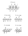
- Figures 2 and 3 are partial plan views of injection nozzles provided in a slit plate of the present invention;
- Figure 4 is a partial sectional view of the lower part of a fluidized bed of Fig. 1;
- Figure 5 (a) and Figure 5 (b) are partial sectional views of one embodiment of the slit plate of the present invention;
- Figure 6 (a) and Figure 6 (b) are partial perspective views of a second embodiment of the slit plate of the present invention;
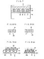
- Figure 7 is a partial sectional view of the lower part of a fluidized bed which is different from the one of Fig.
- Figure 8 (a) and Figure 8 (b) are partial sectional views of a third embodiment of the slit plate of the present invention
- Figure 9 (a) and Figure 9 (b) are partial sectional views different from the above of the lower part of the fluidized bed of the present invention
- Figure 10 (a) to Figure 10 (g) are schematic illustrations of the states of a mixed-phase flow and/or a flow of solid particles which are brought about by various coil arrangement structures in the fluidized bed when the structures of the aforesaid embodiments are employed
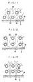
- Figure 11 to Figure 13 are partial sectional views of the fluidized bed of another different embodiment of the present invention
- Figure 14 illustrates one example of the fluidized bed of the present invention utilized as a multi-stage bed
- Figure 15 illustrates one example of the fluidized bed of the present invention utilized in such a manner that a number of beds are juxtaposed
- Figure 16 illustrates one example of the fluidized bed of the present invention utilized in such a manner that a heat exchanger casing in which the fluidized bed of the present invention
- Figure 1 shows one example of the present invention applied to a refrigeration or heat pump cycle, in which numeral 4 denotes a heat exchanger casing, and 1 a heat transmission coil of a heat exchanger provided in said casing 4. This coil is not provided with fins, but formed of a bare tube.
- numeral 2 denotes a fluidized bed, 10 a compressor, and 9 a heat exchanger (condenser and evaporator).
- a cycle comprising the compressor 10, the heat exchanger 9, an expansion valve 8, and the coil 1, etc. operates in the same way as in the case of Fig. 17.
- Numeral 16 denotes a forced draft blower, 18 a slit plate, and 19 an injection nozzle.
- a fluid for cooling down a refrigerant flows into the heat exchanger (condenser) 9 through an inlet 14 and flows out through an outlet 15.
- the jet stream 21 is injected substantially from just below the heat transmission coil 1 of the heat exchanger to form a mixed-phase flow 22 along the circumference of the heat transmission coil so as to make good a convective heat transmission with the coil.
- the pressure loss of the air stream can be reduced, since a net 3 is provided over an opening 23 having a larger passage sectional area than the injection nozzle 19.
- Figure 5 (a) and Figure 5 (b) are longitudinal sectional views of the slit plate 18 having different structures from that of Fig. 4. Since the net 3 is provided over the opening 23 having a larger passage sectional area than the injection nozzle 19, the pressure loss of the stream can be reduced, and that the upper surface of the slit plate 18 is formed by the aggregation of numerous slanting surfaces produces the following advantage. That is, while the solid particles which are not fluidized stay on the upper surface or the upper surface getting wet causes the formation of frost when said surface is flat as shown in Fig. 4, these faults, which occur in the case of Fig. 4, can be removed by forming this surface to be slanting as stated above.
- Figure 6 (a) and Figure 6 (b) show embodiments of the slit plate having different structures from that of Fig. 4.
- the injection nozzle 19 is formed above and the opening 23 having a larger passage sectional area than said nozzle below by bending or curving a plate, and the opening 23 is provided with a net or a punched metal 3.
- the embodiment of Fig. 6 (a) is suitable for mass production, since it can be made of a flat plate, while the embodiment of Fig. 6 (b) is free from the soild particles staying on the upper surface 24, since it is made protuberant upward.
- a group of solid particles staying in a space A when the operation of the fluidized bed stops is fluidized and blown up when the operation of the system is started, and it flows out to a heat exchanging element through the injection nozzles 19.
- no solid particles return to the space A against a high-speed air stream injected from the part of the injection nozzles 19.
- Figure 7 shows an embodiment of the slit plate 18 having a different structure from that of Fig. 4.
- the injection nozzle 19 has the same structure as that of Fig. 2 or 3, and numeral 21 denotes a jet stream and 22 a mixed-phase flow of a gas and solid particles formed around the coil.
- the net 3 is provided on the upstream side a small gap apart from the lower surface of the slit plate 18, and said gap is made small enough to prevent the solid particles from remaining therein during the operation of the fluidized bed.
- Figure 8 (a) and Figure 8 (b) show embodiments of a net provided in an injection port element respectively.
- Numeral 25 denotes a slit-shaped injection port element forming member for generating the jet stream, whose longitudinal section is shown, and 19 denotes the injection nozzle, while 3 denotes the net provided in the injection nozzle.
- the net is set in a direction inclined to the direction of the flow of the jet stream passing through the injection nozzle 19. According to this structure, the pressure loss can be reduced, since the jet stream flows through the net having a larger area than that provided, in the injection nozzle 19, at a right angle to the flowing direction of the jet stream passing through said nozzle.
- Figure 9 (a) and Figure 9 (b) show constructions in which, such a slit plate 18 as shown in Fig. 1 being omitted, the lowermost heat transmission coil 1a is formed so that the adjacent portions thereof are arranged with a small gap 19a between and that said gap itself is thus shaped into a slit by which a fluid passing through the gap is made to be a jet stream.
- a distance S between the net 3 and the coil 1 a is selected appropriately to be small enough to prevent the solid particles from remaining in the aforesaid gap during the operation of the fluidized bed.
- Fig. 9 (a) shows the case in which the heat transmission coil 1a a has a larger diameter than the heat transmission coil 1 on other stages
- Fig. 9 (b) shows the case in which the coil 1a has the same diameter as those on other stages.
- Figure 10 (a) to Figure 10 (g) illustrate schematically the arrangement of the heat transmission coils on two or three stages and the state of a solid-gas mixed phase flow around the heat transmission coils in the above-described embodiments, respectively.
- a state of the mixed-phase flow or the flow of solid particles as illustrated in the respective figure is formed around each heat transmission coil on each stage in accordance with the case in which the heat transmission coils are arranged above and below on the same vertical plane and the case in which said coils are arranged above and below in a zigzag form.
- Fig. 10 (a) to Fig. 10 (e) show the case in which the heat transmission coils are arranged on two stages
- Fig. 10 (f) and Fig. 10 (g) show the case in which the coils are arranged on three stages.
- Figure 12 also shows an embodiment in which a slit plate 18 and a net 3 both having structures similar to those in Fig. 7 are employed. It is different, however, from the embodiment of Fig. 11 in that the heat transmission coils 1 are arranged above and below in the vertical direction and that the injection nozzles 19 are provided at the positions in the slit plate 18 from which the jet stream is injected in the direction slightly deviated from just below the heat transmission coil 1.
- This embodiment also produces an effect that the gas and the solid particles are kept in excellent contact with the surface of each heat transmission coil 1, since the mixed-phase flow 22 of the gas and the solid particles is formed around said coil.
- Figure 13 shows an embodiment in which a slit plate 18 and a net 3 both having structures similar to those in Fig. 12 and heat transmission coils 1 arranged above and below in the vertical direction are employed.
- this embodiment is different from that of Fig. 12 in that a pitch of the transverse arrangement of each heat transmission coil 1 is slightly narrower and that injection nozzles 19 are provided at the positions in the slit plate 18 from which the jet stream is injected toward the middle of a space between the juxtaposed portions of the coil.
- slit plate 18 and the net 3 employed in the embodiments of Figs. 11 to 13 have the same structures as those in Fig. 7, the same good heat transmission effect can be produced, of course, by adopting any one of the structures of Figs. 2 to 6 for generating the jet stream, in place of the aforesaid structures.
- the embodiments of Figs. 11 to 13 are embodiments of the present invention equal to those of Figs. 2 to 10 in that the mixed-phase flow of the gas and the solid particles is formed around the heat transmission coil by the injection of the jet stream and the gas and the solid particles are kept in a good contact with the surface of the coil, thus producing good heat transmission effects.
- the embodiments of Figs. 11 to 13, like those of Figs. 2 to 10, have the construction in which a flat jet stream is injected toward the heat transmission coil from below the coil so that it runs along the direction of the coil, thereby causing the mixed-phase flow of the gas and the solid particles around the heat transmission coil.
- FIG. 14 While a single fluidized bed is provided in the heat exchanger casing 4 in the embodiments described above, a plurality of fluidized beds disposed in a multistage manner can also be provided as shown in Figure 14.
- inner tubes 4a, 4b, 4c ... are provided in said casing 4, and fluidized beds 2a, 2b, 2c are formed inside the inner tubes respectively.
- a gas flowing in through an inlet 26 is separated into a part injected into the fluidized bed 2a and a part flowing between the walls of the casing 4 and the inner tube 4a, and the part of the gas making the fluidized bed 2a operate is discharged through outlets 27a, 27b ..., the operation of each bed being conducted sequentially in such a process.
- the capacity of the heat exchanger can be increased while an occupied space can be reduced by constructing the fluidized bed in multistage in this way.
- Figure 15 shows a construction in which the inside of the heat exchanger casing 4 is divided into four sections each forming a unit, by partition walls 31 and 32, each unit is provided with one of the fluidized beds 2a to 2d, and a gas sent by a common blower is made to flow separately into said fluidized beds 2a to 2d.
- the blower can be designed so that the speed of rotation thereof can be controlled, and a damper can also be provided at an inlet of air into the fluidized beds so as to enable a static pressure control.
- frost When frost is formed even a little on the bare tube coil of the heat exchanger in Fig. 1 in the case where the present invention is used for a heat pump cycle, it is scraped down from the surface of the bare tube by the jet of the solid particles and the air stream in the fluidized bed which make a circulative movement constantly and violently, and it is mixed in the particles of the fluidized bed 2. Then, by a classifying (sizing) action of the fluidized bed 2, the frost smaller in specific gravity than the solid particle is brought upward sequentially through among the particles and separated from the solid particles to spring out into the air to be dispersed outside as tiny pieces together with exhaust air.
- the amount of frost formed on the coil depends on the temperature of the evaporator and that of a gas. When its amount becomes large, the size of the solid particles in the fluidized bed is enlarged in accordance with said amount and low degrees in temperature so as to promote the defrosting effect of the particles.
- the heat exchanger When the present invention is used for a heat exchanger of a cooling operation cycle, the heat exchanger operates as a condenser, and in summertime it operates as an air-cooled condenser. Since it is a condenser utilizing the fluidized bed having an excellent heat transmission coefficient, the radiation of heat into the outside air is facilitated remarkably, and the efficiency of a refrigeration cycle can be improved by lowering the temperature of condensation of a refrigerant.
- the heat exchanger operates as an evaporator in the above described heat pump operation. Since the difference between the temperature of evaporation of the refrigerant and the fluid temperature of the fluidized bed on the occasion can be made small, the temperature of evaporation can be set at high degrees, and thus the efficiency of the heat pump cycle can be improved.
Landscapes
- Engineering & Computer Science (AREA)
- Chemical & Material Sciences (AREA)
- Physics & Mathematics (AREA)
- Thermal Sciences (AREA)
- Mechanical Engineering (AREA)
- General Engineering & Computer Science (AREA)
- Combustion & Propulsion (AREA)
- Organic Chemistry (AREA)
- Chemical Kinetics & Catalysis (AREA)
- Heat-Exchange Devices With Radiators And Conduit Assemblies (AREA)
- Crucibles And Fluidized-Bed Furnaces (AREA)
- Devices And Processes Conducted In The Presence Of Fluids And Solid Particles (AREA)
Claims (7)
Applications Claiming Priority (2)
| Application Number | Priority Date | Filing Date | Title |
|---|---|---|---|
| JP58085/85 | 1985-03-22 | ||
| JP5808585 | 1985-03-22 |
Publications (3)
| Publication Number | Publication Date |
|---|---|
| EP0195436A2 EP0195436A2 (de) | 1986-09-24 |
| EP0195436A3 EP0195436A3 (en) | 1986-12-30 |
| EP0195436B1 true EP0195436B1 (de) | 1989-04-19 |
Family
ID=13074085
Family Applications (1)
| Application Number | Title | Priority Date | Filing Date |
|---|---|---|---|
| EP86103718A Expired EP0195436B1 (de) | 1985-03-22 | 1986-03-19 | Einblassystem mit Strahl-Strömung |
Country Status (5)
| Country | Link |
|---|---|
| US (1) | US4971141A (de) |
| EP (1) | EP0195436B1 (de) |
| JP (1) | JPS6217595A (de) |
| KR (1) | KR900007722B1 (de) |
| DE (1) | DE3662940D1 (de) |
Families Citing this family (11)
| Publication number | Priority date | Publication date | Assignee | Title |
|---|---|---|---|---|
| FR2624401A1 (fr) * | 1987-12-11 | 1989-06-16 | Charbonnages De France | Grille de fluidisation refroidie |
| FR2645046A1 (fr) * | 1989-03-28 | 1990-10-05 | Duong Frederic | Dispositif de fluidisation pour produits solides granulaires a permeabilite variable |
| US5568834A (en) * | 1995-02-01 | 1996-10-29 | Donlee Technologies, Inc. | High temperature heat exchanger |
| DE19613906C2 (de) * | 1996-04-06 | 1998-07-16 | Metallgesellschaft Ag | Anströmboden für eine Wirbelschicht mit Durchtrittsöffnungen für das von unten nach oben strömende Gas |
| US6263958B1 (en) | 1998-02-23 | 2001-07-24 | William H. Fleishman | Heat exchangers that contain and utilize fluidized small solid particles |
| KR100722432B1 (ko) * | 2006-07-28 | 2007-05-28 | 한국에너지기술연구원 | 충돌제트기류를 이용한 폐입자 건조장치 |
| US20110283555A1 (en) * | 2008-11-24 | 2011-11-24 | Rwe Power Aktiengesellschaft | Indirectly heated fluidized bed dryer |
| KR101129956B1 (ko) * | 2010-04-29 | 2012-03-26 | 장한기술 주식회사 | 밀폐형 냉각탑 |
| JP6218439B2 (ja) * | 2013-06-04 | 2017-10-25 | 株式会社前川製作所 | 熱交換体およびそれを用いたベルトコンベア冷却機構並びに冷却機械 |
| CN110953922B (zh) * | 2019-11-27 | 2021-01-15 | 河北涿州京源热电有限责任公司 | 间接空冷系统基于最低防冻允许背压下的最小循环水流量调控方法 |
| KR102328624B1 (ko) * | 2020-03-04 | 2021-11-18 | 공주대학교 산학협력단 | 드론을 통해 수분을 분사하여 미세먼지를 저감하는 미세먼지 저감 장치 |
Family Cites Families (13)
| Publication number | Priority date | Publication date | Assignee | Title |
|---|---|---|---|---|
| US2536099A (en) * | 1947-08-18 | 1951-01-02 | American Metal Co Ltd | Means for forming stages in fluidized masses |
| US2789034A (en) * | 1954-03-30 | 1957-04-16 | Allied Chem & Dye Corp | Process and apparatus for converting finely divided metal sulfide ore into sulfur dioxide and agglomerates of low sulfur cinder |
| GB919308A (en) * | 1961-02-27 | 1963-02-20 | Fawkham Dev Ltd | Improvements in or relating to fluidized bed apparatus |
| BE758006A (fr) * | 1970-06-12 | 1971-04-01 | Brauer Heinz | Procede pour la mise en action d'un reacteur a couches tourbillonnaire |
| US4033555A (en) * | 1971-01-11 | 1977-07-05 | The Motch & Merryweather Machinery Company | Fluidized bed for treating granular material |
| US3829983A (en) * | 1971-10-27 | 1974-08-20 | Phillips Petroleum Co | Grid plate |
| US3814176A (en) * | 1973-01-22 | 1974-06-04 | R Seth | Fixed-fluidized bed dry cooling tower |
| JPS5487675A (en) * | 1977-12-26 | 1979-07-12 | Gadelius Co Ltd | Fluidized bed apparatus |
| JPS5916684Y2 (ja) * | 1979-05-11 | 1984-05-16 | 月島機械株式会社 | 流動層冷却装置 |
| GB2105455A (en) * | 1981-09-09 | 1983-03-23 | Vyzk Ustav Chem Zarizeni | An apparatus for indirect cooling of fluids by a gas stream |
| US4493364A (en) * | 1981-11-30 | 1985-01-15 | Institute Of Gas Technology | Frost control for space conditioning |
| JPS58200994A (ja) * | 1982-05-19 | 1983-11-22 | Toshiba Corp | 流動床熱交換器の分散板 |
| JPS59145486A (ja) * | 1983-02-07 | 1984-08-20 | Komatsu Ltd | 処理品の残留熱回収方法及び装置 |
-
1986
- 1986-03-13 KR KR1019860001820A patent/KR900007722B1/ko not_active Expired
- 1986-03-17 JP JP61058580A patent/JPS6217595A/ja active Granted
- 1986-03-19 DE DE8686103718T patent/DE3662940D1/de not_active Expired
- 1986-03-19 EP EP86103718A patent/EP0195436B1/de not_active Expired
-
1988
- 1988-06-28 US US07/212,065 patent/US4971141A/en not_active Expired - Fee Related
Non-Patent Citations (1)
| Title |
|---|
| PATENTS ABSTRACTS OF JAPAN, vol. 8, no. 87 (M-291)[1524], 20th April 1984; & JP - A - 59 4888 (TOKYO SHIBAURA DENKI K.K.) 11-01-1984 * |
Also Published As
| Publication number | Publication date |
|---|---|
| JPH0467111B2 (de) | 1992-10-27 |
| KR860007530A (ko) | 1986-10-13 |
| JPS6217595A (ja) | 1987-01-26 |
| EP0195436A2 (de) | 1986-09-24 |
| EP0195436A3 (en) | 1986-12-30 |
| US4971141A (en) | 1990-11-20 |
| KR900007722B1 (ko) | 1990-10-19 |
| DE3662940D1 (en) | 1989-05-24 |
Similar Documents
| Publication | Publication Date | Title |
|---|---|---|
| CN1690639B (zh) | 增密的热交换器管束 | |
| KR100518854B1 (ko) | 열교환기 | |
| US4971141A (en) | Jet stream injection system | |
| US5787722A (en) | Heat exchange unit | |
| US4089187A (en) | Condenser-air flow system of a household refrigerator | |
| WO2021227850A1 (zh) | 空调器 | |
| AU2020334589A1 (en) | Refrigerant Distributor and Evaporator Comprising the Refrigerant Distributor | |
| CN115289874A (zh) | 立式换热器及空调机组 | |
| KR100479781B1 (ko) | 증발기 및 냉방기 | |
| CN207146744U (zh) | 蒸发式冷凝温度调节设备 | |
| US6481242B2 (en) | Condenser and freezer | |
| US3990260A (en) | Low-temperature dehumidifier | |
| CN217584650U (zh) | 除湿机 | |
| KR100320726B1 (ko) | 물 직접접촉식 공기조화장치 | |
| CN1880895A (zh) | 一种风冷式冰柜的侧送风方法及采用该方法的风冷式冰柜 | |
| US1919197A (en) | Air conditioning system | |
| KR102169284B1 (ko) | 열교환기 및 이를 갖는 공기조화기 | |
| CN212777708U (zh) | 具有喷淋冷却系统的空调机组 | |
| US3759317A (en) | A heat exchanger | |
| RU2752210C2 (ru) | Теплообменное устройство и способ теплообмена между воздухом и текучей средой, транспортируемой внутри теплообменника | |
| JPH11118293A (ja) | 空気調和機の熱交換器 | |
| US1736408A (en) | Air cooler | |
| US2990700A (en) | Airfoil evaporator with liquid distributor means | |
| KR100357113B1 (ko) | 분리형 공기조화기용 실외기 | |
| CN113654293B (zh) | 一种超低温组合式装配冷库制冷系统 |
Legal Events
| Date | Code | Title | Description |
|---|---|---|---|
| PUAI | Public reference made under article 153(3) epc to a published international application that has entered the european phase |
Free format text: ORIGINAL CODE: 0009012 |
|
| AK | Designated contracting states |
Kind code of ref document: A2 Designated state(s): DE FR GB SE |
|
| PUAL | Search report despatched |
Free format text: ORIGINAL CODE: 0009013 |
|
| AK | Designated contracting states |
Kind code of ref document: A3 Designated state(s): DE FR GB SE |
|
| 17P | Request for examination filed |
Effective date: 19870312 |
|
| 17Q | First examination report despatched |
Effective date: 19870619 |
|
| GRAA | (expected) grant |
Free format text: ORIGINAL CODE: 0009210 |
|
| AK | Designated contracting states |
Kind code of ref document: B1 Designated state(s): DE FR GB SE |
|
| REF | Corresponds to: |
Ref document number: 3662940 Country of ref document: DE Date of ref document: 19890524 |
|
| ET | Fr: translation filed | ||
| PLBE | No opposition filed within time limit |
Free format text: ORIGINAL CODE: 0009261 |
|
| STAA | Information on the status of an ep patent application or granted ep patent |
Free format text: STATUS: NO OPPOSITION FILED WITHIN TIME LIMIT |
|
| 26N | No opposition filed | ||
| EAL | Se: european patent in force in sweden |
Ref document number: 86103718.2 |
|
| PGFP | Annual fee paid to national office [announced via postgrant information from national office to epo] |
Ref country code: GB Payment date: 19990222 Year of fee payment: 14 |
|
| PGFP | Annual fee paid to national office [announced via postgrant information from national office to epo] |
Ref country code: FR Payment date: 19990317 Year of fee payment: 14 |
|
| PGFP | Annual fee paid to national office [announced via postgrant information from national office to epo] |
Ref country code: SE Payment date: 19990323 Year of fee payment: 14 |
|
| PGFP | Annual fee paid to national office [announced via postgrant information from national office to epo] |
Ref country code: DE Payment date: 19990428 Year of fee payment: 14 |
|
| PG25 | Lapsed in a contracting state [announced via postgrant information from national office to epo] |
Ref country code: GB Free format text: LAPSE BECAUSE OF NON-PAYMENT OF DUE FEES Effective date: 20000319 |
|
| PG25 | Lapsed in a contracting state [announced via postgrant information from national office to epo] |
Ref country code: SE Free format text: LAPSE BECAUSE OF NON-PAYMENT OF DUE FEES Effective date: 20000320 |
|
| EUG | Se: european patent has lapsed |
Ref document number: 86103718.2 |
|
| GBPC | Gb: european patent ceased through non-payment of renewal fee |
Effective date: 20000319 |
|
| PG25 | Lapsed in a contracting state [announced via postgrant information from national office to epo] |
Ref country code: FR Free format text: LAPSE BECAUSE OF NON-PAYMENT OF DUE FEES Effective date: 20001130 |
|
| REG | Reference to a national code |
Ref country code: FR Ref legal event code: ST |
|
| PG25 | Lapsed in a contracting state [announced via postgrant information from national office to epo] |
Ref country code: DE Free format text: LAPSE BECAUSE OF NON-PAYMENT OF DUE FEES Effective date: 20010103 |