EP0195128A1 - Device for the continuous production of an endless thin chipboard - Google Patents
Device for the continuous production of an endless thin chipboard Download PDFInfo
- Publication number
- EP0195128A1 EP0195128A1 EP85116145A EP85116145A EP0195128A1 EP 0195128 A1 EP0195128 A1 EP 0195128A1 EP 85116145 A EP85116145 A EP 85116145A EP 85116145 A EP85116145 A EP 85116145A EP 0195128 A1 EP0195128 A1 EP 0195128A1
- Authority
- EP
- European Patent Office
- Prior art keywords
- press
- roller
- belt
- deflecting
- edge
- Prior art date
- Legal status (The legal status is an assumption and is not a legal conclusion. Google has not performed a legal analysis and makes no representation as to the accuracy of the status listed.)
- Granted
Links
Images

Classifications
-
- B—PERFORMING OPERATIONS; TRANSPORTING
- B27—WORKING OR PRESERVING WOOD OR SIMILAR MATERIAL; NAILING OR STAPLING MACHINES IN GENERAL
- B27N—MANUFACTURE BY DRY PROCESSES OF ARTICLES, WITH OR WITHOUT ORGANIC BINDING AGENTS, MADE FROM PARTICLES OR FIBRES CONSISTING OF WOOD OR OTHER LIGNOCELLULOSIC OR LIKE ORGANIC MATERIAL
- B27N3/00—Manufacture of substantially flat articles, e.g. boards, from particles or fibres
- B27N3/08—Moulding or pressing
- B27N3/26—Moulding or pressing characterised by using continuously acting presses having a heated press drum and an endless belt to compress the material between belt and drum
-
- Y—GENERAL TAGGING OF NEW TECHNOLOGICAL DEVELOPMENTS; GENERAL TAGGING OF CROSS-SECTIONAL TECHNOLOGIES SPANNING OVER SEVERAL SECTIONS OF THE IPC; TECHNICAL SUBJECTS COVERED BY FORMER USPC CROSS-REFERENCE ART COLLECTIONS [XRACs] AND DIGESTS
- Y10—TECHNICAL SUBJECTS COVERED BY FORMER USPC
- Y10T—TECHNICAL SUBJECTS COVERED BY FORMER US CLASSIFICATION
- Y10T156/00—Adhesive bonding and miscellaneous chemical manufacture
- Y10T156/17—Surface bonding means and/or assemblymeans with work feeding or handling means
- Y10T156/1702—For plural parts or plural areas of single part
- Y10T156/1712—Indefinite or running length work
- Y10T156/1741—Progressive continuous bonding press [e.g., roll couples]
Definitions
- the invention relates to a device of the type mentioned in the preamble of claim 1 for the continuous production of an endless, thin chipboard web.
- the invention has for its object to avoid the disadvantages in particular of the last-mentioned known device and to create a device of the type in question, which has an even lower price, the operation of which is cheaper in terms of heat expenditure and which achieves all of this without the The quality of the finished chipboard is impaired.
- the basic idea of the invention is, like the last-mentioned known device, to use two different belts, so that they can perform the different tasks in the area of the press roll and in the area of the spreading machine to be able to adapt, but to go for the belt in the area of the spreader from the material steel and instead use a flexible textile belt that can consist of natural and / or plastic fibers and has the ability to take very small radii of curvature, so that it can run around a deflection edge, which can be arranged very close above the steel belt before it comes up onto the press roll - so that there the chip cake resting on the flexible textile belt can be transferred to the steel belt.
- the chip cake therefore only needs to cover an extremely short distance without a moving surface, so that it is fundamentally possible for the pre-pressed chip cake to travel this distance without support, so that no friction can occur and the risk of postponements and quality deterioration of the finished chipboard is avoided is.
- the use of a flexible textile tape also has the advantage that a high-frequency heating device for preheating the chip cake can be used with improved effect, since the textile tape can be produced from a material which has extremely low dielectric losses. This also leads to a very even heating of the chip cake. Since the textile strip is practically not heated in the heating device for preheating the chips, and since the specific heat of the material of the textile strip is also low, the heat losses are further reduced. Overall, thermal energy savings of up to 50% result when the teaching according to the invention is used.
- the deflection edge is advantageously by a wedge-shaped edge of a support table for the flexible band formed.
- This can be designed in an arc shape in order to improve the transfer, in particular also to be able to adapt to the curvature of the counter-pressure roller.
- the deflection edge can have a very small radius of curvature. Despite this small radius of curvature, it is also possible to form the edge by means of a roller with a very small radius or corresponding small rollers, so that there is no friction and therefore no impairment of the flexible textile belt.
- the flexible band is expediently in the direction of travel. inclined downwards in front of the deflection edge. This facilitates the transfer from the flexible belt to the steel belt by using gravity to facilitate the transfer.
- the transfer from the flexible belt to the steel belt is further facilitated by a further development of the invention, in which a pre-press is arranged between the spreader and the press roller.
- a pre-press is arranged between the spreader and the press roller.
- the chip cake already has sufficient strength in the transfer area, so that there is no structural damage.
- the arrangement of a heating device, in particular a high-frequency heating device, between the spreading machine and the pre-press also has a favorable effect. This favors the pre-pressing and the behavior and structure of the chip cake is so favored that even under difficult conditions no structural damage to the pre-pressed chip cake can occur in the transfer area.
- the heating device for preheating the chip cake is expediently dimensioned such that the chips are heated to a temperature of about 50-60 ° C. As a result, as much heat as possible is supplied without the binder with which the chips are already being cured hardening.
- the pre-press so that the chip cake entering the pre-press is compressed by no more than 50%, preferably by 10%.
- This very low pre-compression is just sufficient to ensure the transfer of the pre-pressed chip cake from the textile belt to the steel belt without impairing the structure, but at the same time the formation of bonds between the chips before entry into the actual press nip between the press roll and the counter-pressure roll, with respect to which the There is a risk of permanent reopening when entering the press nip.
- the support rail for the chip cake provided between the deflection roller or deflection rollers and the steel belt is expediently cooled and is provided with a cooling channel for this purpose.
- means are provided for guiding a paper web onto the steel strip before it runs onto the press roll.
- the paper web thus runs directly in front of the press nip, which is possible by dividing it into steel strips and textile strips.
- the paper web therefore does not have to be fed in front of the spreader, which would mean a large length of the paper web in front of the press nip, via which strains can occur in the paper band, which lead to changes in the structure of the poured chip cake and thus to impaired quality of the finished chipboard.
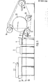
- chips mixed with a binder are scattered onto a textile belt 2, which is spread by the scattering machine 1 through a high-frequency heating device 3, through a pre-press 4, over a curved table 5, over its front deflecting edge 6 and is returned to the spreader via deflection rollers 7 to 11.
- the press device for the final pressing has a press roller 12 which is partially wrapped in a steel belt 13 which is guided around a deflection roller 14, a tension roller 15, a pressure roller 16 and a counter-pressure roller 17 which presses the steel belt 13 against the pressure roller 12 and thus forms a press nip between the two.
- the press pressure is maintained in the area after this press nip by the tension of the steel strip 13, this pressure being sufficient for the remaining setting of the binder until it leaves the press roll 12.
- the deflection edge 6 of the table 5 is located fairly close to the press nip between the pressure roller 17 and the pressure roller 12 and just above the pressure roller 17, so that the pre-pressed chip cake lying on the textile belt 2 runs onto the top of the steel belt 13 with practically no change of direction and on enters the press nip.
- chips which have been mixed with binder by the scattering machine 1 are continuously sprinkled onto the continuously rotating textile belt 2.
- This chip cake thus formed is placed in the high-frequency heating device 3 Temperature warmed, which is harmless to the textile tape 2 and otherwise below the setting temperature of the binder. This preheating increases the compressibility of the chip cake in the subsequent pre-press 4.
- the chip cake After leaving the pre-press 4, the chip cake has a substantially reduced thickness and already has such a strength that a transfer ...., of the pre-pressed chip cake without structural damage from the textile belt 2 to the Steel strip 13 is possible in the area of the deflection edge 6. It is of course assumed that the textile belt 2 and the steel belt 13 have essentially the same rotational speed.
- Fig. 2 shows the right part of FIG. 1, but a spool 18 is provided, from which a paper web 19 runs over a deflecting roller 20 onto the steel belt 13 close to the press nip between the press roller 12 and the counter-pressure roller 17. From the point of impact of the paper web 19 on the steel belt 13 to; to the press nip, the paper web 19 already lies firmly on the steel belt 13 wrapping around the counter-pressure roller 17, so that no relative movements between the two are possible. In addition, the chip cake is already pressed together in this area, so that the paper web can no longer carry out length changes which would lead to an impairment of the chip cake. The paper web 19 is therefore laminated onto the chipboard web in the press nip without impairing quality.
- a spool 21 can also be provided on the upper side, from which a second paper web 22 runs over a deflecting roller 23 onto the press roller 12 immediately before the press nip.
- Fig. 3 shows a greatly enlarged section of Fig. 1 in the area of the press nip between the press roller 12 and the counter-pressure roller 17.
- 5 small deflection rollers 24 are provided at the end of the table around which the textile belt 2 runs. These rollers have a diameter of approximately 6 mm and their axis is held on the front edge of the table 5 by comb-like projections which reach between the rollers.
- pre-pressed chip cake 25 behind the guide rollers 24 there is a flat support rail 26 with a triangular cross-section through which a cooling channel 27 extends.
- the support surface of this support rail 26 extends approximately along the tangent to the deflection rollers 24 and the counter-pressure roller 17th
Abstract
Einrichtung zur kontinuierlichen Herstellung einer endlosen dünnen Spanplattenbahn, bei der über einem waagerecht verlaufenden Teil eines kontinuierlich umlaufenden und gespannten Bandes (2) eine Streumaschine (1) für mit Bindemittel versetzte Holzspäne angeordnet ist. Die Einrichtung weist eine beheizte Preßwalze (12) auf, gegen die ein endloses Stahlband (13) mit seiner Oberseite aufläuft und die von dem Stahlband (13) teilweise umschlungen ist, derart, daß zwischen dem Stahlband (13) und der Preßwalze (12) ein Preßspalt gebildet ist. Außerdem ist eine Gegendruckwalze (17) vorgesehen, die das Band im Bereich des Auflaufs des Stahlbandes (13) auf die Preßwalze (12) gegen diese drückt. Der Durchmesser der Preßwalze (12) ist so groß gewählt, daß die Bindung zwischen den Spänen beim Geradebiegen der fertiggepreßten Spanplattenbahn nicht beeinträchtigt wird. Das unterhalb der Streumaschine (1) verlaufende, endlose Band ist ein flexibles Textilband (2), das von der Streumaschine (1) zu einer Umlenk-kante (6) dicht oberhalb des Stahlbandes (13) vor dessen Auflauf auf die Preßwalze (12) und von dort zurück zur Streumaschine (1) geführt ist. Die Einrichtung hat einen geringen Preis und Energieverbrauch, ohne daß die Qualitat der fertigen Spanplatte beeinträchtigt ist.Device for the continuous production of an endless thin particle board web, in which a spreading machine (1) for wood chips mixed with binder is arranged over a horizontal part of a continuously rotating and tensioned belt (2). The device has a heated press roll (12) against which an endless steel strip (13) runs with its upper side and which is partially wrapped around by the steel strip (13), such that between the steel strip (13) and the press roll (12) a press nip is formed. In addition, a counter-pressure roller (17) is provided which presses the band in the region of the run-up of the steel band (13) onto the press roller (12) against it. The diameter of the press roller (12) is chosen so large that the bond between the chips is not impaired when the finished particle board web is bent straight. The endless belt running underneath the spreader (1) is a flexible textile belt (2) that extends from the spreader (1) to a deflection edge (6) just above the steel belt (13) before it hits the press roll (12). and from there back to the spreader (1). The device has a low price and energy consumption without affecting the quality of the finished chipboard.
Description
Die Erfindung betrifft eine Einrichtung der im Oberbegriff des Anspruchs 1 genannten Art zur kontinuierlichen Herstellung einer endlosen, dünnen Spanplattenbahn.The invention relates to a device of the type mentioned in the preamble of claim 1 for the continuous production of an endless, thin chipboard web.
Durch die DE-PS 20 34 853 ist eine Einrichtung der betreffenden Art bekannt, bei der das unterhalb der Streumaschine verlaufende Band durch das Stahlband gebildet ist, das die beheizte Preßwalze umschlingt. Wegen der hohen,spezifischen Wärme des Materials des Stahlbandes wird die von diesem beim Umlauf um die beheizte Preßwalze aufgenommene Wärme mitgenommen und beim Umlauf über Umlenkwalzen an diese und im übrigen auch durch Strahlung und Abkühlung an der Luft wieder abgegeben, wodurch Wärmeverluste entstehen. Diese Wärmeabgabe ist aber auch erforderlich und muß'sogar durch Kühlung unterstützt werden, da das Stahlband im Bereich der Streumaschine eine Temperatur nicht überschreiten darf, bei der das Bindemittel der von der Streumaschine aufgestreuten Späne noch nicht bindet. Bei der Abkühlung des verhältnismäßig langen Stahlbandes ergeben sich auch Ungleichmäßigkeiten in der Abkühlung zwischen den Randbereichen und dem mittleren Bereich, was zu Spannungen im Stahl und zu vorzeitigen Brüchen, zumindest von Rissen, führen kann. Wegen der Rückführung des Stahlbandes zu der Streumaschine ergibt sich auch eine große Länge des Stahlbandes und wegen seines hohen Meterpreises auch ein großer Kostenaufwand dafür.From DE-PS 20 34 853 a device of the type in question is known, in which the belt running below the spreader is formed by the steel belt which wraps around the heated press roll. Because of the high, specific heat of the material of the steel strip, the heat absorbed by it during the circulation around the heated press roll is carried away and released to the latter via the deflection rolls and also by radiation and cooling in the air, which results in heat losses. This heat dissipation is also necessary and must even be supported by cooling, since the steel strip in the area of the spreader must not exceed a temperature at which the binding agent of the chips scattered by the spreader does not yet bind. When the relatively long steel strip cools, there are also irregularities in the cooling between the edge regions and the central region, which can lead to stresses in the steel and to premature fractures, at least of cracks. Because of the return of the steel strip to the spreading machine, there is also a large length of the steel strip and, because of its high price per meter, also a great expense.
Durch die DE-OS 27 10 000 ist eine Einrichtung der betreffenden Art bekannt, bei der_das unterhalb der Streumaschine verlaufende Band genauso wie das die Preßwalze umschlingende Band ein Stahlband ist, das jedoch ein von dem die Preßwalze umschlingenden Stahlband getrenntes, endloses Stahlband ist, das nicht so hohen Zugbelastungen ausgesetzt werden muß wie-das die Preßwalze umschlingende Stahlband und daher aus Stahl geringerer Qualität bestehen kann und damit billiger ist. Darüber hinaus kann es billiger sein, weil die mindestens zwei Umlenkwalzen für dieses Stahlband einen geringeren Durchmesser haben können. Der Durchmesser ist aber immer noch so groß, daß zwischen der in Laufrichtung letzten Umlenkwalze und der Gegendruckwalze ein langer Zwischenraum verbleibt. Aus diesem Grunde ist bei dieser bekannten Einrichtung ein langes Führungsteil vorgesehen, das den gestreuten und vorgepreßten Spankuchen über die Strecke zwischen der oberen Tangente an die letzte Umlenkwalze und die Gegendruckwalze führen soll. Die Reibung des Spankuchens auf diesem langen Führungsteil ist jedoch so groß, daß es zu Aufschiebungen im vorgepreßten Spankuchen kommt, die die innere Struktur der einzelnen Späne verändern und die durch die Vorpressung bereits entstandenen Bindungen zwischen den Spänen wieder zerstören. Die fertiggepreßte Spanplatte hat daher schlechte Festigkeitseigenschaften.From DE-OS 27 10 000 a device of the type in question is known, in which the belt running underneath the spreader, just like the belt wrapping around the press roll, is a steel belt, but which is an endless steel belt which is separate from the steel belt wrapping around the press roll does not have to be subjected to as high tensile loads as that of the steel belt that wraps around the press roll and can therefore consist of steel of lower quality and is therefore cheaper. In addition, it can be cheaper because the at least two deflecting rollers for this steel strip can have a smaller diameter. However, the diameter is still so large that there is a long space between the last deflection roller in the running direction and the counter-pressure roller. For this reason, a long guide part is provided in this known device, which should guide the scattered and pre-pressed chip cake over the distance between the upper tangent to the last deflecting roller and the counter-pressure roller. The friction of the chip cake on this long guide part is so great, however, that there are delays in the pre-pressed chip cake, which change the internal structure of the individual chips and destroy the bonds between the chips already created by the pre-pressing. The finished pressed chipboard therefore has poor strength properties.
Der Erfindung liegt die Aufgabe zugrunde, die Nachteile insbesondere der zuletzt genannten, bekannten Einrichtung zu vermeiden und eine Einrichtung der betreffenden Art zu schaffen, die einen noch geringeren Preis hat, deren Betrieb hinsichtlich des Wärmeaufwandes verbilligt ist und die alles dies erreicht, ohne daß die Qualität der fertigen Spanplatte beeinträchtigt ist.The invention has for its object to avoid the disadvantages in particular of the last-mentioned known device and to create a device of the type in question, which has an even lower price, the operation of which is cheaper in terms of heat expenditure and which achieves all of this without the The quality of the finished chipboard is impaired.
Die der Erfindung zugrundeliegende Aufgabe wird durch die im Kennzeichen des Anspruchs 1 angegebene Lehre gelöst.The object on which the invention is based is achieved by the teaching specified in the characterizing part of claim 1.
Der Grundgedanke der Erfindung besteht darin, ebenso wie die zuletzt genannte, bekannte Einrichtung zwei verschiedene Bänder zu verwenden, um sie so den unterschiedlichen Aufgaben im Bereich der Preßwalze und im Bereich der Streumaschine anpassen zu können, jedoch für das Band im Bereich der Streumaschine vom Material Stahl abzugehen und statt dessen ein flexibles Textilband zu verwenden, das aus Natur- und/oder Kunststoffasern bestehen kann und die Fähigkeit hat, sehr kleine Krümmungsradien einnehmen zu können, so daß es um eine Umlenkkante laufen kann, die sehr dicht oberhalb des Stahlbandes vor dessen Auflauf auf die Preßwalze angeordnet sein - kann, so daß dort eine Übergabe des auf dem flexiblen Textilband aufliegenden Spankuchens auf das Stahlband erfolgen kann. Der Spankuchen braucht daher nur eine extrem kurze Strecke ohne sich bewegende Unterlage zurückzulegen, so daß es grundsätzlich möglich ist, daß der vorgepreßte Spankuchen diese Wegstrecke ohne Unterstützung durchläuft, so daß keine Reibung auftreten kann und die Gefahr von Aufschiebungen und Qualitätsverschle cherungen der fertigen Spanplatte vermieden ist.The basic idea of the invention is, like the last-mentioned known device, to use two different belts, so that they can perform the different tasks in the area of the press roll and in the area of the spreading machine to be able to adapt, but to go for the belt in the area of the spreader from the material steel and instead use a flexible textile belt that can consist of natural and / or plastic fibers and has the ability to take very small radii of curvature, so that it can run around a deflection edge, which can be arranged very close above the steel belt before it comes up onto the press roll - so that there the chip cake resting on the flexible textile belt can be transferred to the steel belt. The chip cake therefore only needs to cover an extremely short distance without a moving surface, so that it is fundamentally possible for the pre-pressed chip cake to travel this distance without support, so that no friction can occur and the risk of postponements and quality deterioration of the finished chipboard is avoided is.
Aber selbst dann, wenn in diesem Übergangsbereich von der Umlenkkante des flexiblen Textilbandes zu dem Stahlband bzw. der Gegendruckwalze gemäß einer Weiterbildung der Erfindung eine Auflageschiene angeordnet ist, so kann diese doch so kurz in Bewegungsrichtung des vorgepreßten Spankuchens sein, daß die durch die Auflage auf der Oberseite dieser Auflageschiene entstehende Reibung so gering ist, daß die Gefahr von Aufschiebungen nicht besteht.But even if a support rail is arranged in this transition area from the deflection edge of the flexible textile belt to the steel belt or the counter-pressure roller according to a development of the invention, it can be so short in the direction of movement of the pre-pressed chip cake that the through the support on the friction on the top of this support rail is so low that there is no risk of suspensions.
Die Verwendung eines flexiblen Textilbandes hat außerdem den Vorteil, daß sich mit verbesserter Wirkung eine Hochfrequenzheizeinrichtung zum Vorwärmen des Spankuchens verwenden läßt, da das Textilband sich aus einem Material herstellen läßt, das extrem geringe dielektrische Verluste hat. Dies führt außerdem zu einer sehr gleichmäßigen Durchwärmung des Spankuchens. Da eine Erwärmung des Textilbandes in der Heizeinrichtung zum Vorwärmen der Späne praktisch nicht erfolgt und da darüber hinaus die spezifische Wärme des Materials des Textilbandes gering ist, verringern sich dadurch weiter die Wärmeverluste. Insgesamt ergeben sich bei Anwendung der erfindungsgemäßen Lehre Wärmeenergieeinsparungen bis zu 50 %.The use of a flexible textile tape also has the advantage that a high-frequency heating device for preheating the chip cake can be used with improved effect, since the textile tape can be produced from a material which has extremely low dielectric losses. This also leads to a very even heating of the chip cake. Since the textile strip is practically not heated in the heating device for preheating the chips, and since the specific heat of the material of the textile strip is also low, the heat losses are further reduced. Overall, thermal energy savings of up to 50% result when the teaching according to the invention is used.
Die Umlenkkante ist zweckmäßigerweise durch eine keilförmig ausgebildete Kante eines Auflagetisches für das flexible Band gebildet. Dieser kann bogenförmig ausgebildet sein, um die Übergabe zu verbessern, insbesondere auch um sich dem Krümmungsverlauf der Gegendruckwalze anpassen zu können.The deflection edge is advantageously by a wedge-shaped edge of a support table for the flexible band formed. This can be designed in an arc shape in order to improve the transfer, in particular also to be able to adapt to the curvature of the counter-pressure roller.
Je nach der Art des Textilbandes kann die Umlenkkante einen sehr kleinen Krümmungsradius haben. Trotz dieses kleinen Krümmungsradiusses ist es aber auch möglich, die Kante durch eine Walze mit-sehr kleinem Radius oder entsprechende kleine - Rollen auszubilden, so daß keine Reibung und damit auch keine Beeinträchtigung des flexiblen Textilbandes entstehen kann.Depending on the type of textile tape, the deflection edge can have a very small radius of curvature. Despite this small radius of curvature, it is also possible to form the edge by means of a roller with a very small radius or corresponding small rollers, so that there is no friction and therefore no impairment of the flexible textile belt.
Das flexible Band ist zweckmäßigerweise in Laufrichtung- . vor der Umlenkkante nach unten geneigt. Dadurch wird die Übergabe von dem flexiblen Band auf das Stahlband erleichtert, indem die Schwerkraft mit zur Erleichterung der Übergabe herangezogen wird.The flexible band is expediently in the direction of travel. inclined downwards in front of the deflection edge. This facilitates the transfer from the flexible belt to the steel belt by using gravity to facilitate the transfer.
Die Übergabe von dem flexiblen Band auf das Stahlband wird weiterhin erleichtert durch eine Weiterbildung der Erfindung, bei der eine Vorpresse zwischen der Streumaschine und der Preßwalze angeordnet ist. Der Spankuchen hat dadurch im Übergabebereich bereits eine ausreichende Festigkeit, so daß keine Gefügebeeinträchtigung entsteht. In gleicher Weise günstig wirkt auch die Anordnung einer Heizeinrichtung, insbesondere einer Hochfrequenzheizeinrichtung, zwischen Streumaschine und Vorpresse. Dadurch wird das Vorpressen begünstigt und das Verhalten und das Gefüge des Spankuchens so begünstigt, daß auch unter schwierigen Verhältnissen keine Gefügebeeinträchtigungen des vorgepreßten Spankuchens im Übergabebereich entstehen können.The transfer from the flexible belt to the steel belt is further facilitated by a further development of the invention, in which a pre-press is arranged between the spreader and the press roller. As a result, the chip cake already has sufficient strength in the transfer area, so that there is no structural damage. The arrangement of a heating device, in particular a high-frequency heating device, between the spreading machine and the pre-press also has a favorable effect. This favors the pre-pressing and the behavior and structure of the chip cake is so favored that even under difficult conditions no structural damage to the pre-pressed chip cake can occur in the transfer area.
Die Heizeinrichtung zum Vorwärmen des Spankuchens ist zweckmäßigerweise so bemessen, daß die Späne auf eine Temperatur von etwa 50 - 60° C erwärmt werden. Dadurch wird soviel Wärme wie möglich zugeführt, ohne daß bereits eine Aushärtung des Bindemittels erfolgt, mit dem die Späne versetzt sind.The heating device for preheating the chip cake is expediently dimensioned such that the chips are heated to a temperature of about 50-60 ° C. As a result, as much heat as possible is supplied without the binder with which the chips are already being cured hardening.
Gemäß einer anderen Weiterbildung der Erfindung ist die . Vorpresse so bemessen, daß der in die Vorpresse einlaufende Spankuchen um nicht mehr als 50 %, vorzugsweise um 10 %, verdichtet wird. Diese sehr geringe Vorverdichtung reicht gerade aus, um die Übergabe des vorgepreßten Spankuchens von dem Textilband auf das Stahlband ohne Gefügebeeinträchtigung sicherzustellen, gleichzeitig wird jedoch das Entstehen von Bindungen zwischen den Spänen vor dem Einlauf in den eigentlichen Preßspalt zwischen Preßwalze und Gegendruckwalze vermieden, bezüglich denen die Gefahr eines bleibenden Wiederaufbrechens beim Einlauf in den Preßspalt besteht.According to another development of the invention. Dimension the pre-press so that the chip cake entering the pre-press is compressed by no more than 50%, preferably by 10%. This very low pre-compression is just sufficient to ensure the transfer of the pre-pressed chip cake from the textile belt to the steel belt without impairing the structure, but at the same time the formation of bonds between the chips before entry into the actual press nip between the press roll and the counter-pressure roll, with respect to which the There is a risk of permanent reopening when entering the press nip.
Die gemäß einer Weiterbildung der Erfindung zwischen Umlenkwalze oder Umlenkrollen und dem Stahlband vorgesehene Auflageschiene für den Spankuchen ist zweckmäßigerweise gekühlt und hierzu mit einem Kühlkanal versehen. Dadurch wird eine Erwärmung dieser Auflageschiene durch Wärmestrahlung von dem Stahlband bzw. der Gegendruckwalze her und damit eine entsprechende Temperaturerhöhung der auf der Auflageschiene aufliegenden Schicht des Spankuchens vermieden und damit auch ein Aushärten des Bindemittels, bevor die endgültige Zusammenpressung des Spankuchens erfolgt ist.According to a further development of the invention, the support rail for the chip cake provided between the deflection roller or deflection rollers and the steel belt is expediently cooled and is provided with a cooling channel for this purpose. As a result, heating of this support rail by heat radiation from the steel strip or the counter-pressure roller and thus a corresponding increase in temperature of the layer of the chip cake lying on the support rail is avoided and thus also a hardening of the binder before the chip cake is finally compressed.
Schließlich sind gemäß einer Weiterbildung der Erfindung Mittel zur Aufleitung einer Papierbahn auf das Stahlband vor dessen Auflauf auf die Preßwalze vorgesehen. Die Papierbahn läuft also unmittelbar vor dem Preßspalt zu, was durch die Aufteilung in Stahlband und Textilband möglich ist. Die Papierbahn braucht somit nicht bereits vor der Streumaschine zugeführt zu werden, was eine große Länge der Papierbahn vor dem Preßspalt bedeuten würde, über die Dehnungen im Papierband erfolgen können, die zu Änderungen des Gefüges des geschütteten Spankuchens und damit zu Qualitätsbeeinträchtigungen der fertigen Spanplatte führen.Finally, according to a further development of the invention, means are provided for guiding a paper web onto the steel strip before it runs onto the press roll. The paper web thus runs directly in front of the press nip, which is possible by dividing it into steel strips and textile strips. The paper web therefore does not have to be fed in front of the spreader, which would mean a large length of the paper web in front of the press nip, via which strains can occur in the paper band, which lead to changes in the structure of the poured chip cake and thus to impaired quality of the finished chipboard.
Anhand der Zeichnung soll die Erfindung näher erläutert werden.
- Fig. 1 zeigt schematisch ein Ausführungsbeispiel der Erfindung,
- Fig. 2 zeigt den rechten Teil der Fig. 1 und verdeutlicht eine Weiterbildung der Erfindung,
- Fig. 3 zeigt einen vergrößerten Ausschnitt der Fig. 1 im Bereich im und kurz vor dem Preßspalt.
- 1 schematically shows an embodiment of the invention,
- 2 shows the right part of FIG. 1 and illustrates a further development of the invention,
- Fig. 3 shows an enlarged section of Fig. 1 in the area in and just before the press nip.
Bei der Einrichtung gemäß Fig. 1 werden mittels einer Streumaschine 1 mit einem Bindemittel versetzte Späne auf ein Textilband 2 gestreut, das von der Streumaschine 1 durch eine Hochfrequenzheizeinrichtung 3, durch eine Vorpresse 4, über einen gebogenen Tisch 5, über dessen vordere Umlenkkante 6 sowie über Umlenkrollen 7 bis 11 zu der Streumaschine zurückgeführt ist.In the device according to FIG. 1, by means of a scattering machine 1, chips mixed with a binder are scattered onto a
Die Preßeinrichtung zum Fertigpressen weist eine Preßwalze 12 auf, die teilweise von einem Stahlband 13 umschlungen ist, das um eine Umlenkwalze 14, eine Spannwalze 15, eine Andruckwalze 16 und eine Gegendruckwalze 17 geführt ist, die das Stahlband 13 gegen die Preßwalze 12 drückt und somit zwischen beiden einen Preßspalt bildet. Der Preßdruck wird im Bereich nach diesem Preßspalt durch die Spannung des Stahlbandes 13 aufrechterhalten, wobei dieser Druck für die restliche Abbindung des Bindemittels bis zum Verlassen der Preßwalze 12 ausreicht.The press device for the final pressing has a
Die Umlenkkante 6 des Tisches 5 befindet sich ziemlich dicht vor dem Preßspalt zwischen der Gegendruckwalze 17 und der Preßwalze 12 und dicht oberhalb der Gegendruckwalze 17, so daß auf dem Textilband 2 aufliegender, vorgepreßter Spankuchen praktisch ohne Richtungsänderung auf die Oberseite des Stahlbandes 13 aufläuft und weiter in den Preßspalt einläuft. Bei Betrieb der Einrichtung werden fortwährend durch-die Streumaschine 1 mit Bindemittel versetzte Späne auf das kontinuierlich umlaufende Textilband 2 aufgestreut. Dieser so gebildete Spankuchen wird in der Hochfrequenzheizeinrichtung 3 auf eine Temperatur erwärmt, die für das Textilband 2 unschädlich und im übrigen unterhalb der Abbindetemperatur des Bindesmittels liegt. Diese Vorheizung erhöht die Zusammenpreßbarkeit des Spankuchens in der nachfolgenden Vorpresse 4. Nach Verlassen der Vorpresse 4 hat der Spankuchen eine wesentlich verringerte Dicke und bereits eine solche Festigkeit, daß eine Übergabe...., des vorgepreßten Spankuchens ohne Gefügebeeinträchtigung von dem Textilband 2 auf das Stahlband 13 im Bereich der Umlenk- kante 6 möglich ist. Dabei ist natürlich vorausgesetzt, daß das Textilband 2 und das Stahlband 13 im wesentlichen die gleiche Umlaufgeschwindigkeit haben.The deflection edge 6 of the table 5 is located fairly close to the press nip between the
Fig. 2 zeigt den rechten Teil der Fig. 1, wobei jedoch eine Spule 18 vorgesehen ist, von der eine Papierbahn 19 über eine Umlenkwalze 20 auf das Stahlband 13 dicht vor dem Preßspalt zwischen Preßwalze 12 und Gegendruckwalze 17 aufläuft. Von dem Auflaufpunkt der Papierbahn 19 auf das Stahlband 13 bis; zu dem Preßspalt liegt die Papierbahn 19 bereits fest auf dem die Gegendruckwalze 17 umschlingenden Stahlband 13 auf, so daß keine Relativbewegungen zwischen beiden möglich sind. Außerdem wird der Spankuchen in diesem Bereich bereits zusammengepreßt, so daß die Papierbahn keine Längenänderungen mehr ausführen kann, die zu einer Beeinträchtigung des Spankuchens führen würden. Die Papierbahn 19 wird daher ohne Qualitätsbeeinträchtigungen bei der Herstellung der Spanplattenbahn im Preßspalt auf diese aufkaschiert.Fig. 2 shows the right part of FIG. 1, but a
In gleicher Weise kann auch auf der Oberseite eine Spule 21 vorgesehen sein, von der eine zweite Papierbahn 22 über eine Umlenkwalze 23 auf die Preßwalze 12 unmittelbar vor dem Preßspalt aufläuft.In the same way, a
Fig. 3 zeigt stark vergrößert einen Ausschnitt der Fig. 1 im Bereich des Preßspaltes zwischen der Preßwalze 12 und der Gegendruckwalze 17. Es ist zu erkennen, daß am Ende des Tisches 5 kleine Umlenkrollen 24 vorgesehen sind, um die das Textilband 2 läuft. Diese Rollen haben einen Durchmesser von ungefähr 6 mm, und ihre Achse ist durch zwischen die Rollen greifende, kammartige Vorsprünge an der vorderen Kante des Tisches 5 gehalten. In Bewegungsrichtung eines auf dem Textilband 2 aufliegenden, vorgepreßten Spankuchens 25 hinter den Umlenkrollen 24 befindet sich eine im Querschnitt dreieckige, flache Auflageschiene 26, durch die sich ein Kühlkanal 27 erstreckt. Die Auflagefläche dieser Auflageschiene 26 erstreckt sich etwa entlang der Tangente an die Umlenkrollen 24 und die Gegendruckwalze 17.Fig. 3 shows a greatly enlarged section of Fig. 1 in the area of the press nip between the
Claims (19)
Priority Applications (1)
| Application Number | Priority Date | Filing Date | Title |
|---|---|---|---|
| AT85116145T ATE53182T1 (en) | 1985-03-22 | 1985-12-18 | EQUIPMENT FOR THE CONTINUOUS PRODUCTION OF AN ENDLESS, THIN CHIPBOARD WEB. |
Applications Claiming Priority (4)
| Application Number | Priority Date | Filing Date | Title |
|---|---|---|---|
| DE3510460 | 1985-03-22 | ||
| DE3510460 | 1985-03-22 | ||
| DE3541286 | 1985-11-22 | ||
| DE19853541286 DE3541286A1 (en) | 1985-03-22 | 1985-11-22 | DEVICE FOR THE CONTINUOUS PRODUCTION OF AN ENDLESS, THIN CHIPBOARD |
Publications (2)
| Publication Number | Publication Date |
|---|---|
| EP0195128A1 true EP0195128A1 (en) | 1986-09-24 |
| EP0195128B1 EP0195128B1 (en) | 1990-05-30 |
Family
ID=25830632
Family Applications (1)
| Application Number | Title | Priority Date | Filing Date |
|---|---|---|---|
| EP85116145A Expired - Lifetime EP0195128B1 (en) | 1985-03-22 | 1985-12-18 | Device for the continuous production of an endless thin chipboard |
Country Status (11)
| Country | Link |
|---|---|
| US (1) | US4744854A (en) |
| EP (1) | EP0195128B1 (en) |
| JP (1) | JPH0671723B2 (en) |
| CN (1) | CN1012048B (en) |
| CA (1) | CA1266607A (en) |
| DE (1) | DE3541286A1 (en) |
| DK (1) | DK162333C (en) |
| ES (1) | ES8704788A1 (en) |
| FI (1) | FI82409C (en) |
| MX (1) | MX165176B (en) |
| SU (1) | SU1505434A3 (en) |
Cited By (3)
| Publication number | Priority date | Publication date | Assignee | Title |
|---|---|---|---|---|
| WO2010118609A1 (en) * | 2009-04-15 | 2010-10-21 | 敦化市亚联机械制造有限公司 | Continuous rolling machine with a flexible hot pressboard |
| EP3017924A1 (en) * | 2014-11-06 | 2016-05-11 | Flooring Technologies Ltd. | Method for manufacturing a wooden panel, in particular a wood-plastic composite |
| US10369721B2 (en) | 2014-11-06 | 2019-08-06 | Flooring Technologies Ltd. | Wooden material panel, in particular in the form of a wood-plastic composite material, and a method for producing the same |
Families Citing this family (22)
| Publication number | Priority date | Publication date | Assignee | Title |
|---|---|---|---|---|
| DE3725383C1 (en) * | 1987-07-31 | 1988-12-01 | Siempelkamp Gmbh & Co | Plant for the hot pressing of pressed material mats in the production of chipboard, fibreboard and the like. |
| DE3734180C2 (en) * | 1987-10-09 | 1998-01-29 | Kuesters Eduard Maschf | Double belt press for the production of chipboard and the like |
| DE3804042A1 (en) * | 1988-02-10 | 1989-08-17 | Mende & Co W | Apparatus for producing chipboards |
| US5223071A (en) * | 1989-02-02 | 1993-06-29 | Hermann Berstorff Maschinenbau Gmbh | Apparatus for producing chip and fiberboard webs of uniform thickness |
| DE3914780C2 (en) * | 1989-05-05 | 1997-12-04 | Mende & Co W | Device for the continuous production of an endless, thin chipboard web and method for painting a surface of thin chipboard provided with a paper coating |
| DE3937421C1 (en) * | 1989-11-10 | 1991-01-24 | Hermann Berstorff Maschinenbau Gmbh, 3000 Hannover, De | |
| US5295805A (en) * | 1990-03-02 | 1994-03-22 | Ryoka Techno Engineering & Construction Co. | Rotating cylindrical treatment apparatus |
| DE4031171C3 (en) * | 1990-10-03 | 1998-07-09 | Siempelkamp Gmbh & Co | Press system for pressing pressed material mats in the course of the production of chipboard |
| US5277108A (en) * | 1990-11-08 | 1994-01-11 | Mitsubishi Kasei Engineering Co. | Rotating cylindrical treatment apparatus |
| US5792306A (en) * | 1996-10-18 | 1998-08-11 | Fmc Corporation | Sealing apparatus useful in bag-making machine |
| NL1010620C2 (en) * | 1998-11-20 | 2000-05-23 | Klieverik Heli Bv | Laminator. |
| DE19854661A1 (en) * | 1998-11-26 | 2000-05-31 | Dieffenbacher Gmbh Maschf | Continuous production of boards using wood and other vegetable materials uses initial air extraction press where material is covered by paper webs and cover with barrier papers through continuous press |
| JP2003102770A (en) * | 2001-09-28 | 2003-04-08 | Johnson & Johnson Kk | Seal device |
| US6989068B2 (en) * | 2004-04-23 | 2006-01-24 | Eastman Kodak Company | Roller chain for applying pressure |
| US8221109B2 (en) | 2006-12-05 | 2012-07-17 | Gold Tip, Llc | Material layering device |
| US9056412B2 (en) * | 2009-12-30 | 2015-06-16 | The Procter & Gamble Company | Process for the production of high internal phase emulsion foams |
| CN104520080B (en) * | 2012-08-09 | 2017-02-22 | 塞拉洛克创新股份有限公司 | Single layer scattering of powder surfaces |
| CN106003361A (en) * | 2016-07-14 | 2016-10-12 | 重庆市创农木制品包装箱有限公司 | Uniform blank forming system of artificial board |
| CN106003355A (en) * | 2016-07-14 | 2016-10-12 | 重庆市创农木制品包装箱有限公司 | Uniform board blank forming system for artificial boards |
| CN106003360A (en) * | 2016-07-14 | 2016-10-12 | 重庆市创农木制品包装箱有限公司 | Artificial plate blank forming system |
| CN105946088A (en) * | 2016-07-14 | 2016-09-21 | 重庆市创农木制品包装箱有限公司 | Beautiful board blank forming system for artificial board |
| CN106003359A (en) * | 2016-07-14 | 2016-10-12 | 重庆市创农木制品包装箱有限公司 | Environmental-friendly board blank forming system for artificial boards |
Citations (4)
| Publication number | Priority date | Publication date | Assignee | Title |
|---|---|---|---|---|
| DE802360C (en) * | 1950-01-18 | 1951-02-08 | Erwin Dipl-Ing Hahnel | Veneer joint gluing and glazing machine |
| DE2458409A1 (en) * | 1973-12-10 | 1975-06-19 | Mets Konstrukt | Moving fibre cakes for fibreboard - scattering fibres on transport belt, compressing them with thin film of adhesive to form fleece, and removing to main transport belt |
| AT343882B (en) * | 1972-04-14 | 1978-06-26 | Berstorff Gmbh Masch Hermann | PROCESS FOR ONE-SIDED OR BOTH-SIDED CONTINUOUS LAMINATION OF ALREADY PRESSED, THIN SHEETS WITH A DECORATIVE LAYER |
| DE2710000A1 (en) * | 1977-03-08 | 1978-09-14 | Berstorff Gmbh Masch Hermann | EQUIPMENT FOR THE CONTINUOUS MANUFACTURING OF CHIPBOARD, FIBERBOARD OR THE SAME |
Family Cites Families (10)
| Publication number | Priority date | Publication date | Assignee | Title |
|---|---|---|---|---|
| US3039137A (en) * | 1958-02-10 | 1962-06-19 | American Biltrite Rubber Co | Apparatus for forming plastic sheets |
| US3565725A (en) * | 1967-01-31 | 1971-02-23 | Eugen Siempelkamp | Apparatus for making pressed boards from particulate material |
| US3450030A (en) * | 1967-10-03 | 1969-06-17 | Siempelkamp Eugen | Method and apparatus for the charging of platen presses |
| BE757468A (en) * | 1970-07-14 | 1971-03-16 | Mende & Co W | SYSTEM FOR CONTINUOUS MANUFACTURING OF AGGLOMERATED CHIP BOARDS |
| DE2034853B2 (en) * | 1970-07-14 | 1973-09-13 | Mende & Co W | Continuous chipboard prodn - compacting in arcuate press gap between heated drum and ravelling belt |
| US3994765A (en) * | 1972-03-29 | 1976-11-30 | Hermann Berstorff Maschinenbau Gmbh | Endless pressure belt for laminating chipboard panels |
| DE2523670B2 (en) * | 1975-05-28 | 1978-11-02 | Feldmuehle Ag, 4000 Duesseldorf | Process for the continuous production and simultaneous coating of chipboard, which is covered with at least one cover layer made of synthetic resin-impregnated paper |
| US4310365A (en) * | 1979-12-26 | 1982-01-12 | Western Electric Company, Inc. | Methods for the manufacture of multi-conductor flat cable |
| DE3104035C2 (en) * | 1980-03-06 | 1984-10-18 | Esselte Pendaflex Corp., Garden City, N.Y. | Device for printing, dispensing and attaching self-adhesive labels adhering to a carrier tape |
| US4253902A (en) * | 1980-06-24 | 1981-03-03 | Sansei Seiki Co., Ltd. | Automatic labeler |
-
1985
- 1985-11-22 DE DE19853541286 patent/DE3541286A1/en active Granted
- 1985-12-18 EP EP85116145A patent/EP0195128B1/en not_active Expired - Lifetime
-
1986
- 1986-01-03 FI FI860021A patent/FI82409C/en not_active IP Right Cessation
- 1986-01-14 ES ES550840A patent/ES8704788A1/en not_active Expired
- 1986-01-24 DK DK036086A patent/DK162333C/en not_active IP Right Cessation
- 1986-02-06 SU SU864017574A patent/SU1505434A3/en active
- 1986-02-21 MX MX1624A patent/MX165176B/en unknown
- 1986-03-20 US US06/841,880 patent/US4744854A/en not_active Expired - Lifetime
- 1986-03-20 JP JP61061021A patent/JPH0671723B2/en not_active Expired - Lifetime
- 1986-03-21 CN CN86101826A patent/CN1012048B/en not_active Expired
- 1986-03-24 CA CA000504901A patent/CA1266607A/en not_active Expired - Fee Related
Patent Citations (4)
| Publication number | Priority date | Publication date | Assignee | Title |
|---|---|---|---|---|
| DE802360C (en) * | 1950-01-18 | 1951-02-08 | Erwin Dipl-Ing Hahnel | Veneer joint gluing and glazing machine |
| AT343882B (en) * | 1972-04-14 | 1978-06-26 | Berstorff Gmbh Masch Hermann | PROCESS FOR ONE-SIDED OR BOTH-SIDED CONTINUOUS LAMINATION OF ALREADY PRESSED, THIN SHEETS WITH A DECORATIVE LAYER |
| DE2458409A1 (en) * | 1973-12-10 | 1975-06-19 | Mets Konstrukt | Moving fibre cakes for fibreboard - scattering fibres on transport belt, compressing them with thin film of adhesive to form fleece, and removing to main transport belt |
| DE2710000A1 (en) * | 1977-03-08 | 1978-09-14 | Berstorff Gmbh Masch Hermann | EQUIPMENT FOR THE CONTINUOUS MANUFACTURING OF CHIPBOARD, FIBERBOARD OR THE SAME |
Cited By (4)
| Publication number | Priority date | Publication date | Assignee | Title |
|---|---|---|---|---|
| WO2010118609A1 (en) * | 2009-04-15 | 2010-10-21 | 敦化市亚联机械制造有限公司 | Continuous rolling machine with a flexible hot pressboard |
| EP3017924A1 (en) * | 2014-11-06 | 2016-05-11 | Flooring Technologies Ltd. | Method for manufacturing a wooden panel, in particular a wood-plastic composite |
| US10369721B2 (en) | 2014-11-06 | 2019-08-06 | Flooring Technologies Ltd. | Wooden material panel, in particular in the form of a wood-plastic composite material, and a method for producing the same |
| US11072087B2 (en) | 2014-11-06 | 2021-07-27 | Flooring Technologies Ltd. | Wooden material panel, in particular in the form of a wood-plastic composite material, and a method for producing the same |
Also Published As
| Publication number | Publication date |
|---|---|
| DK162333C (en) | 1992-03-09 |
| FI860021A (en) | 1986-09-23 |
| JPS61220803A (en) | 1986-10-01 |
| CN1012048B (en) | 1991-03-20 |
| ES550840A0 (en) | 1987-05-01 |
| DK36086D0 (en) | 1986-01-24 |
| DE3541286C2 (en) | 1993-07-08 |
| FI860021A0 (en) | 1986-01-03 |
| US4744854A (en) | 1988-05-17 |
| SU1505434A3 (en) | 1989-08-30 |
| DK36086A (en) | 1986-09-23 |
| DE3541286A1 (en) | 1986-09-25 |
| JPH0671723B2 (en) | 1994-09-14 |
| CN86101826A (en) | 1986-10-08 |
| CA1266607A (en) | 1990-03-13 |
| MX165176B (en) | 1992-10-30 |
| FI82409B (en) | 1990-11-30 |
| FI82409C (en) | 1991-03-11 |
| DK162333B (en) | 1991-10-14 |
| EP0195128B1 (en) | 1990-05-30 |
| ES8704788A1 (en) | 1987-05-01 |
Similar Documents
| Publication | Publication Date | Title |
|---|---|---|
| EP0195128B1 (en) | Device for the continuous production of an endless thin chipboard | |
| DE2722356C2 (en) | Method and device for the continuous production of chipboard, fiber or the like. plates | |
| DE4333614C2 (en) | Process and plant for the continuous production of chipboard | |
| DE936718C (en) | Crawler press for the production of chipboard | |
| DD280065A5 (en) | METHOD FOR THE PRODUCTION OF WOOD CHIPPLATES AND DGL. AND CORRESPONDING DOUBLE BAND PRESSES | |
| EP2714351B1 (en) | Method and plant for producing material boards | |
| DE3502608A1 (en) | METHOD AND DEVICE FOR BONDING TEXTILE AREAS | |
| DE2126935A1 (en) | Device for pressing chipboard | |
| DE3704940C2 (en) | ||
| DD250290A5 (en) | METHOD FOR CONTINUOUS MANUFACTURE OF CHIP, FIBER AND SIMILAR PLATES | |
| EP0458806B1 (en) | Process and installation for manufacturing particle boards and the like | |
| DE10101952A1 (en) | Continual production of chip or fibre board, comprises scattering a material and a binding agent onto a transport band, then passing the band between two steel bands, where the material is heated and pressed | |
| DE3914780C2 (en) | Device for the continuous production of an endless, thin chipboard web and method for painting a surface of thin chipboard provided with a paper coating | |
| DD241226A5 (en) | DEVICE FOR CONTINUOUS MANUFACTURE OF A FINISHED, THIN SPIDER PLATFORM TRACK | |
| DE2829817C3 (en) | Method and apparatus for producing chipboard, fiber or the like. plates | |
| DE1703637C3 (en) | Device for the continuous production of a thin, endless chipboard sheet | |
| DE2360141C3 (en) | Device for the continuous production of an endless chipboard web, fibreboard web or the like | |
| DE2355797B2 (en) | Press for exerting a surface pressure | |
| DE8508630U1 (en) | Device for the continuous production of an endless, thin chipboard sheet | |
| DE2120016C3 (en) | Device for continuous pressing | |
| DE2034853B2 (en) | Continuous chipboard prodn - compacting in arcuate press gap between heated drum and ravelling belt | |
| DE3414381A1 (en) | Device for transferring a fleece from a fleece carrier into a press | |
| EP1261476A1 (en) | Extruder for vegetable small parts, which are mixed with a binding agent, for producing compact strands | |
| DE2603111A1 (en) | Continuous sheet prodn. from particles plus thermoplastic binder - by depositing on moving web of thin disposable film | |
| DE2149339A1 (en) | Fibre-or chipboard,continuous prodn - using steel bands and supporting rollers to give a hot press section |
Legal Events
| Date | Code | Title | Description |
|---|---|---|---|
| PUAI | Public reference made under article 153(3) epc to a published international application that has entered the european phase |
Free format text: ORIGINAL CODE: 0009012 |
|
| AK | Designated contracting states |
Kind code of ref document: A1 Designated state(s): AT BE CH FR GB IT LI LU NL SE |
|
| 17P | Request for examination filed |
Effective date: 19861016 |
|
| 17Q | First examination report despatched |
Effective date: 19871102 |
|
| GRAA | (expected) grant |
Free format text: ORIGINAL CODE: 0009210 |
|
| AK | Designated contracting states |
Kind code of ref document: B1 Designated state(s): AT BE CH FR GB IT LI LU NL SE |
|
| REF | Corresponds to: |
Ref document number: 53182 Country of ref document: AT Date of ref document: 19900615 Kind code of ref document: T |
|
| GBT | Gb: translation of ep patent filed (gb section 77(6)(a)/1977) | ||
| ET | Fr: translation filed | ||
| ITF | It: translation for a ep patent filed |
Owner name: MODIANO & ASSOCIATI S.R.L. |
|
| ITTA | It: last paid annual fee | ||
| PLBE | No opposition filed within time limit |
Free format text: ORIGINAL CODE: 0009261 |
|
| STAA | Information on the status of an ep patent application or granted ep patent |
Free format text: STATUS: NO OPPOSITION FILED WITHIN TIME LIMIT |
|
| 26N | No opposition filed | ||
| EPTA | Lu: last paid annual fee | ||
| EAL | Se: european patent in force in sweden |
Ref document number: 85116145.5 |
|
| PGFP | Annual fee paid to national office [announced via postgrant information from national office to epo] |
Ref country code: FR Payment date: 19990930 Year of fee payment: 15 |
|
| PGFP | Annual fee paid to national office [announced via postgrant information from national office to epo] |
Ref country code: LU Payment date: 19991126 Year of fee payment: 15 |
|
| PGFP | Annual fee paid to national office [announced via postgrant information from national office to epo] |
Ref country code: BE Payment date: 19991129 Year of fee payment: 15 |
|
| PGFP | Annual fee paid to national office [announced via postgrant information from national office to epo] |
Ref country code: CH Payment date: 19991208 Year of fee payment: 15 |
|
| PGFP | Annual fee paid to national office [announced via postgrant information from national office to epo] |
Ref country code: GB Payment date: 19991213 Year of fee payment: 15 |
|
| PGFP | Annual fee paid to national office [announced via postgrant information from national office to epo] |
Ref country code: SE Payment date: 19991217 Year of fee payment: 15 |
|
| PGFP | Annual fee paid to national office [announced via postgrant information from national office to epo] |
Ref country code: NL Payment date: 19991227 Year of fee payment: 15 Ref country code: AT Payment date: 19991227 Year of fee payment: 15 |
|
| PG25 | Lapsed in a contracting state [announced via postgrant information from national office to epo] |
Ref country code: LU Free format text: LAPSE BECAUSE OF NON-PAYMENT OF DUE FEES Effective date: 20001218 Ref country code: GB Free format text: LAPSE BECAUSE OF NON-PAYMENT OF DUE FEES Effective date: 20001218 Ref country code: AT Free format text: LAPSE BECAUSE OF NON-PAYMENT OF DUE FEES Effective date: 20001218 |
|
| PG25 | Lapsed in a contracting state [announced via postgrant information from national office to epo] |
Ref country code: SE Free format text: LAPSE BECAUSE OF NON-PAYMENT OF DUE FEES Effective date: 20001219 |
|
| PG25 | Lapsed in a contracting state [announced via postgrant information from national office to epo] |
Ref country code: LI Free format text: LAPSE BECAUSE OF NON-PAYMENT OF DUE FEES Effective date: 20001231 Ref country code: CH Free format text: LAPSE BECAUSE OF NON-PAYMENT OF DUE FEES Effective date: 20001231 Ref country code: BE Free format text: LAPSE BECAUSE OF NON-PAYMENT OF DUE FEES Effective date: 20001231 |
|
| BERE | Be: lapsed |
Owner name: WILHELM MENDE G.M.B.H. & CO. Effective date: 20001231 |
|
| PG25 | Lapsed in a contracting state [announced via postgrant information from national office to epo] |
Ref country code: NL Free format text: LAPSE BECAUSE OF NON-PAYMENT OF DUE FEES Effective date: 20010701 |
|
| GBPC | Gb: european patent ceased through non-payment of renewal fee |
Effective date: 20001218 |
|
| EUG | Se: european patent has lapsed |
Ref document number: 85116145.5 |
|
| REG | Reference to a national code |
Ref country code: CH Ref legal event code: PL |
|
| PG25 | Lapsed in a contracting state [announced via postgrant information from national office to epo] |
Ref country code: FR Free format text: LAPSE BECAUSE OF NON-PAYMENT OF DUE FEES Effective date: 20010831 |
|
| NLV4 | Nl: lapsed or anulled due to non-payment of the annual fee |
Effective date: 20010701 |
|
| REG | Reference to a national code |
Ref country code: FR Ref legal event code: ST |