EP0194976B1 - Vorrichtung zum schnellen Verbinden zweier Elemente in nichtparallelen Ebenen - Google Patents
Vorrichtung zum schnellen Verbinden zweier Elemente in nichtparallelen Ebenen Download PDFInfo
- Publication number
- EP0194976B1 EP0194976B1 EP86830013A EP86830013A EP0194976B1 EP 0194976 B1 EP0194976 B1 EP 0194976B1 EP 86830013 A EP86830013 A EP 86830013A EP 86830013 A EP86830013 A EP 86830013A EP 0194976 B1 EP0194976 B1 EP 0194976B1
- Authority
- EP
- European Patent Office
- Prior art keywords
- elements
- wall
- hole
- appendix
- rapid connection
- Prior art date
- Legal status (The legal status is an assumption and is not a legal conclusion. Google has not performed a legal analysis and makes no representation as to the accuracy of the status listed.)
- Expired
Links
Images
Classifications
-
- F—MECHANICAL ENGINEERING; LIGHTING; HEATING; WEAPONS; BLASTING
- F16—ENGINEERING ELEMENTS AND UNITS; GENERAL MEASURES FOR PRODUCING AND MAINTAINING EFFECTIVE FUNCTIONING OF MACHINES OR INSTALLATIONS; THERMAL INSULATION IN GENERAL
- F16B—DEVICES FOR FASTENING OR SECURING CONSTRUCTIONAL ELEMENTS OR MACHINE PARTS TOGETHER, e.g. NAILS, BOLTS, CIRCLIPS, CLAMPS, CLIPS OR WEDGES; JOINTS OR JOINTING
- F16B5/00—Joining sheets or plates, e.g. panels, to one another or to strips or bars parallel to them
- F16B5/02—Joining sheets or plates, e.g. panels, to one another or to strips or bars parallel to them by means of fastening members using screw-thread
- F16B5/0291—Joining sheets or plates, e.g. panels, to one another or to strips or bars parallel to them by means of fastening members using screw-thread the threaded element being driven through the edge of a sheet plate with its axis in the plane of the plate
-
- F—MECHANICAL ENGINEERING; LIGHTING; HEATING; WEAPONS; BLASTING
- F16—ENGINEERING ELEMENTS AND UNITS; GENERAL MEASURES FOR PRODUCING AND MAINTAINING EFFECTIVE FUNCTIONING OF MACHINES OR INSTALLATIONS; THERMAL INSULATION IN GENERAL
- F16B—DEVICES FOR FASTENING OR SECURING CONSTRUCTIONAL ELEMENTS OR MACHINE PARTS TOGETHER, e.g. NAILS, BOLTS, CIRCLIPS, CLAMPS, CLIPS OR WEDGES; JOINTS OR JOINTING
- F16B37/00—Nuts or like thread-engaging members
- F16B37/04—Devices for fastening nuts to surfaces, e.g. sheets, plates
- F16B37/041—Releasable devices
- F16B37/043—Releasable devices with snap action
Definitions
- the present invention concerns a device for the rapid connection of two elements on nonparallel planes, or of two mutually orthogonal or sloping walls.
- the known devices are generally not fit to guarantee a rapid connection of two elements when, instead of being positioned on parallel planes, they are on orthogonal or sloping walls or on nonparallel planes. It is also known from US-A-3 970 399 a fastener assembly for securing a pair of contiguous standards at substantially right angles relative to each other which includes a fastener comprising first and second perpendicularly oriented webs, and means mounted on the second web for connecting a standard thereto.
- the purpose of the present invention is to provide a device for the rapid connection on non parallel planes of two elements having walls, said device consisting of a body having two supporting sides to lie against the walls of the two elements to be connected and forming the angle at which the elements are connected, the first one of said sides having a hole fully or partly piercing the body of the device and fit to be engaged by fastening means fastening the wall of the first element to said body, characterised in that the second one of said sides has an appendix which is expanded under the action of said fastening means and is thereby fastened into an aperture in the wall of the second element.
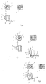
- numeral 2 shows the device consisting of a body having a hole 3 fully or partly piercing it, fit to receive the fastening element 4 through the hole 8 of the wall or the first element 6, and of an appendix 5.
- Appendix 5 has a mushroom-shape and proper slots, at least one of which is so deep as to reach the hole 3; the resulting projections 9 are consequently fit to engage into the aperture 7 made in the wall of the second element 1, which may be either rectangular or square (Fig. 1).
- the appendix 5 of the device 2, with the projections 9, will have the same rectangular or square shape to allow the fastening of the first element 1 with respect to the second element 6 in onyl one spatial position.
- the aperture 7 made in the wall of the second element 1 is circular.
- the appendix 5 of the device, with the projections 9, will have the same circular shape to allow a spatially free fastening of the second element 1 with respect to the first element 6.
- Fig. 3 shows a third embodiment of the device 2 when the walls of the two elements 1 and 6 are not on orthogonal planes.
- the technician can rotate the body 2 fastening the first element 6 with respect to the second element 1 in the desired position.
Landscapes
- Engineering & Computer Science (AREA)
- General Engineering & Computer Science (AREA)
- Mechanical Engineering (AREA)
- Connection Of Plates (AREA)
- Joining Of Building Structures In Genera (AREA)
- Branch Pipes, Bends, And The Like (AREA)
Claims (4)
Applications Claiming Priority (2)
| Application Number | Priority Date | Filing Date | Title |
|---|---|---|---|
| IT5296885U | 1985-02-08 | ||
| ITTO1985U52968U IT8552968U1 (it) | 1985-02-08 | 1985-02-08 | Dispositivo di collegamento rapido di due elementi disposti su piani non paralleli. |
Publications (2)
| Publication Number | Publication Date |
|---|---|
| EP0194976A1 EP0194976A1 (de) | 1986-09-17 |
| EP0194976B1 true EP0194976B1 (de) | 1989-04-12 |
Family
ID=11278927
Family Applications (1)
| Application Number | Title | Priority Date | Filing Date |
|---|---|---|---|
| EP86830013A Expired EP0194976B1 (de) | 1985-02-08 | 1986-01-20 | Vorrichtung zum schnellen Verbinden zweier Elemente in nichtparallelen Ebenen |
Country Status (4)
| Country | Link |
|---|---|
| EP (1) | EP0194976B1 (de) |
| DE (1) | DE3662806D1 (de) |
| ES (1) | ES292186Y (de) |
| IT (1) | IT8552968U1 (de) |
Families Citing this family (2)
| Publication number | Priority date | Publication date | Assignee | Title |
|---|---|---|---|---|
| US5674023A (en) * | 1995-11-27 | 1997-10-07 | Delco Electronics Corporation | Fastener clip and joint assembly |
| SE0104153L (sv) * | 2001-06-03 | 2002-12-04 | Hortinorr Ab | Anordning vid sammanfogning av plåt och balk vinkelrätt mot varandra |
Family Cites Families (5)
| Publication number | Priority date | Publication date | Assignee | Title |
|---|---|---|---|---|
| US2624386A (en) * | 1947-03-12 | 1953-01-06 | John R Russell | Driven nut |
| US3498655A (en) * | 1968-09-18 | 1970-03-03 | Hewlett Packard Co | Panel mount and fastener |
| US3970399A (en) * | 1975-02-10 | 1976-07-20 | Louis Marx & Co., Inc. | Fastener assembly and fastener thereof |
| US4188148A (en) * | 1978-09-20 | 1980-02-12 | Durango Systems, Inc. | Fastener assembly |
| US4338755A (en) * | 1979-06-06 | 1982-07-13 | Chichester Jr S Tebbs | Fastener assembly |
-
1985
- 1985-02-08 IT ITTO1985U52968U patent/IT8552968U1/it unknown
-
1986
- 1986-01-20 DE DE8686830013T patent/DE3662806D1/de not_active Expired
- 1986-01-20 EP EP86830013A patent/EP0194976B1/de not_active Expired
- 1986-02-07 ES ES1986292186U patent/ES292186Y/es not_active Expired
Also Published As
| Publication number | Publication date |
|---|---|
| IT8552968U1 (it) | 1986-08-08 |
| DE3662806D1 (en) | 1989-05-18 |
| IT8552968V0 (it) | 1985-02-08 |
| EP0194976A1 (de) | 1986-09-17 |
| ES292186Y (es) | 1987-08-16 |
| ES292186U (es) | 1987-01-01 |
Similar Documents
| Publication | Publication Date | Title |
|---|---|---|
| US4650386A (en) | Fully articulable positioning device | |
| US4641474A (en) | Sta-put wallboard joiner | |
| CA1133565A (en) | Device for assembling and connecting to one another constructive elements particularly panels for furniture and like | |
| US4244083A (en) | Cable clamp | |
| JPH08128420A (ja) | 連結材 | |
| US3071827A (en) | Fastening device | |
| US4532682A (en) | Connection for a jewelry band | |
| EP0194976B1 (de) | Vorrichtung zum schnellen Verbinden zweier Elemente in nichtparallelen Ebenen | |
| KR960007965A (ko) | 성형된 표면 파스너 | |
| US5233870A (en) | Single post stud with locking blade | |
| US3292479A (en) | Snap socket fastener | |
| US4986006A (en) | Apparatus for locating a connector plate or the like | |
| DE59003024D1 (de) | Gerätegehäuse mit zwei gehäuseschalen. | |
| JPH0135928Y2 (de) | ||
| JPH0320105A (ja) | 組み立て家具 | |
| JPH0356941Y2 (de) | ||
| JPH0717850Y2 (ja) | 電気部品用クリップ | |
| JPH02940Y2 (de) | ||
| JPH0134382Y2 (de) | ||
| KR910009588Y1 (ko) | 모니터 스탠드 착탈장치 | |
| JPH0643339Y2 (ja) | パネルの取付装置 | |
| JPH0610177Y2 (ja) | クリツプ | |
| JP3795174B2 (ja) | 簡易組立て式デスク | |
| JPS6146083Y2 (de) | ||
| JPS6028147Y2 (ja) | 携帯用電子機器保持装置 |
Legal Events
| Date | Code | Title | Description |
|---|---|---|---|
| PUAI | Public reference made under article 153(3) epc to a published international application that has entered the european phase |
Free format text: ORIGINAL CODE: 0009012 |
|
| AK | Designated contracting states |
Kind code of ref document: A1 Designated state(s): DE FR GB SE |
|
| 17P | Request for examination filed |
Effective date: 19860916 |
|
| R17P | Request for examination filed (corrected) |
Effective date: 19860916 |
|
| 17Q | First examination report despatched |
Effective date: 19871210 |
|
| GRAA | (expected) grant |
Free format text: ORIGINAL CODE: 0009210 |
|
| AK | Designated contracting states |
Kind code of ref document: B1 Designated state(s): DE FR GB SE |
|
| REF | Corresponds to: |
Ref document number: 3662806 Country of ref document: DE Date of ref document: 19890518 |
|
| ET | Fr: translation filed | ||
| PLBE | No opposition filed within time limit |
Free format text: ORIGINAL CODE: 0009261 |
|
| STAA | Information on the status of an ep patent application or granted ep patent |
Free format text: STATUS: NO OPPOSITION FILED WITHIN TIME LIMIT |
|
| 26N | No opposition filed | ||
| PGFP | Annual fee paid to national office [announced via postgrant information from national office to epo] |
Ref country code: GB Payment date: 19940111 Year of fee payment: 9 |
|
| PGFP | Annual fee paid to national office [announced via postgrant information from national office to epo] |
Ref country code: FR Payment date: 19940128 Year of fee payment: 9 |
|
| PGFP | Annual fee paid to national office [announced via postgrant information from national office to epo] |
Ref country code: DE Payment date: 19940331 Year of fee payment: 9 |
|
| PG25 | Lapsed in a contracting state [announced via postgrant information from national office to epo] |
Ref country code: GB Effective date: 19950120 |
|
| PGFP | Annual fee paid to national office [announced via postgrant information from national office to epo] |
Ref country code: SE Payment date: 19950127 Year of fee payment: 10 |
|
| EAL | Se: european patent in force in sweden |
Ref document number: 86830013.8 |
|
| GBPC | Gb: european patent ceased through non-payment of renewal fee |
Effective date: 19950120 |
|
| PG25 | Lapsed in a contracting state [announced via postgrant information from national office to epo] |
Ref country code: FR Effective date: 19950929 |
|
| PG25 | Lapsed in a contracting state [announced via postgrant information from national office to epo] |
Ref country code: DE Effective date: 19951003 |
|
| REG | Reference to a national code |
Ref country code: FR Ref legal event code: ST |
|
| PG25 | Lapsed in a contracting state [announced via postgrant information from national office to epo] |
Ref country code: SE Effective date: 19960121 |
|
| EUG | Se: european patent has lapsed |
Ref document number: 86830013.8 |