EP0193702B1 - Mixing valve, in particular with a single lever - Google Patents
Mixing valve, in particular with a single lever Download PDFInfo
- Publication number
- EP0193702B1 EP0193702B1 EP19860100222 EP86100222A EP0193702B1 EP 0193702 B1 EP0193702 B1 EP 0193702B1 EP 19860100222 EP19860100222 EP 19860100222 EP 86100222 A EP86100222 A EP 86100222A EP 0193702 B1 EP0193702 B1 EP 0193702B1
- Authority
- EP
- European Patent Office
- Prior art keywords
- water
- fitting according
- mixing fitting
- water mixing
- measuring circuit
- Prior art date
- Legal status (The legal status is an assumption and is not a legal conclusion. Google has not performed a legal analysis and makes no representation as to the accuracy of the status listed.)
- Expired
Links
Images


Classifications
-
- F—MECHANICAL ENGINEERING; LIGHTING; HEATING; WEAPONS; BLASTING
- F16—ENGINEERING ELEMENTS AND UNITS; GENERAL MEASURES FOR PRODUCING AND MAINTAINING EFFECTIVE FUNCTIONING OF MACHINES OR INSTALLATIONS; THERMAL INSULATION IN GENERAL
- F16K—VALVES; TAPS; COCKS; ACTUATING-FLOATS; DEVICES FOR VENTING OR AERATING
- F16K37/00—Special means in or on valves or other cut-off apparatus for indicating or recording operation thereof, or for enabling an alarm to be given
- F16K37/0025—Electrical or magnetic means
- F16K37/005—Electrical or magnetic means for measuring fluid parameters
-
- F—MECHANICAL ENGINEERING; LIGHTING; HEATING; WEAPONS; BLASTING
- F16—ENGINEERING ELEMENTS AND UNITS; GENERAL MEASURES FOR PRODUCING AND MAINTAINING EFFECTIVE FUNCTIONING OF MACHINES OR INSTALLATIONS; THERMAL INSULATION IN GENERAL
- F16K—VALVES; TAPS; COCKS; ACTUATING-FLOATS; DEVICES FOR VENTING OR AERATING
- F16K11/00—Multiple-way valves, e.g. mixing valves; Pipe fittings incorporating such valves
- F16K11/02—Multiple-way valves, e.g. mixing valves; Pipe fittings incorporating such valves with all movable sealing faces moving as one unit
- F16K11/06—Multiple-way valves, e.g. mixing valves; Pipe fittings incorporating such valves with all movable sealing faces moving as one unit comprising only sliding valves, i.e. sliding closure elements
- F16K11/078—Multiple-way valves, e.g. mixing valves; Pipe fittings incorporating such valves with all movable sealing faces moving as one unit comprising only sliding valves, i.e. sliding closure elements with pivoted and linearly movable closure members
- F16K11/0782—Single-lever operated mixing valves with closure members having flat sealing faces
- F16K11/0787—Single-lever operated mixing valves with closure members having flat sealing faces with both the supply and the discharge passages being on the same side of the closure members
-
- G—PHYSICS
- G05—CONTROLLING; REGULATING
- G05D—SYSTEMS FOR CONTROLLING OR REGULATING NON-ELECTRIC VARIABLES
- G05D23/00—Control of temperature
- G05D23/01—Control of temperature without auxiliary power
- G05D23/13—Control of temperature without auxiliary power by varying the mixing ratio of two fluids having different temperatures
- G05D23/1393—Control of temperature without auxiliary power by varying the mixing ratio of two fluids having different temperatures characterised by the use of electric means
-
- E—FIXED CONSTRUCTIONS
- E03—WATER SUPPLY; SEWERAGE
- E03C—DOMESTIC PLUMBING INSTALLATIONS FOR FRESH WATER OR WASTE WATER; SINKS
- E03C1/00—Domestic plumbing installations for fresh water or waste water; Sinks
- E03C1/02—Plumbing installations for fresh water
- E03C1/04—Water-basin installations specially adapted to wash-basins or baths
- E03C2001/0418—Water-basin installations specially adapted to wash-basins or baths having temperature indicating means
-
- Y—GENERAL TAGGING OF NEW TECHNOLOGICAL DEVELOPMENTS; GENERAL TAGGING OF CROSS-SECTIONAL TECHNOLOGIES SPANNING OVER SEVERAL SECTIONS OF THE IPC; TECHNICAL SUBJECTS COVERED BY FORMER USPC CROSS-REFERENCE ART COLLECTIONS [XRACs] AND DIGESTS
- Y10—TECHNICAL SUBJECTS COVERED BY FORMER USPC
- Y10S—TECHNICAL SUBJECTS COVERED BY FORMER USPC CROSS-REFERENCE ART COLLECTIONS [XRACs] AND DIGESTS
- Y10S323/00—Electricity: power supply or regulation systems
- Y10S323/906—Solar cell systems
-
- Y—GENERAL TAGGING OF NEW TECHNOLOGICAL DEVELOPMENTS; GENERAL TAGGING OF CROSS-SECTIONAL TECHNOLOGIES SPANNING OVER SEVERAL SECTIONS OF THE IPC; TECHNICAL SUBJECTS COVERED BY FORMER USPC CROSS-REFERENCE ART COLLECTIONS [XRACs] AND DIGESTS
- Y10—TECHNICAL SUBJECTS COVERED BY FORMER USPC
- Y10T—TECHNICAL SUBJECTS COVERED BY FORMER US CLASSIFICATION
- Y10T137/00—Fluid handling
- Y10T137/8158—With indicator, register, recorder, alarm or inspection means
-
- Y—GENERAL TAGGING OF NEW TECHNOLOGICAL DEVELOPMENTS; GENERAL TAGGING OF CROSS-SECTIONAL TECHNOLOGIES SPANNING OVER SEVERAL SECTIONS OF THE IPC; TECHNICAL SUBJECTS COVERED BY FORMER USPC CROSS-REFERENCE ART COLLECTIONS [XRACs] AND DIGESTS
- Y10—TECHNICAL SUBJECTS COVERED BY FORMER USPC
- Y10T—TECHNICAL SUBJECTS COVERED BY FORMER US CLASSIFICATION
- Y10T137/00—Fluid handling
- Y10T137/8593—Systems
- Y10T137/86493—Multi-way valve unit
- Y10T137/86815—Multiple inlet with single outlet
Definitions
- the invention relates to a water mixer fitting, in particular a single-lever mixer fitting, with on the one hand preferably two water inlets, two water inlet valves, a mixing chamber, an ice water outlet, possibly a water outlet valve and at least one actuator for the water inlet valves and possibly the water outlet valve and with an electronic temperature measuring circuit, on the one hand, the Temperature measuring circuit arranged in the mixed water outlet temperature sensor, a mixed temperature display and a current source, for. B. has a battery or an accumulator.
- Water mixer taps of the type in question are known for wash basins, bathtubs, showers, bidets, etc. They are generally used to mix water of different temperatures - cold water and hot water - flowing in via the water inlets to mixed water of a desired temperature flowing out at the mixed water outlet. So that you can determine how high the temperature of the mixed water is, for example not to scald yourself with water that is too hot, the water mixer taps of the type from which the invention is based have a temperature measuring circuit, which then also includes a mixed temperature display.
- each water inlet valve was previously assigned its own actuating element in the form of a control handle, but that single lever mixer taps are increasingly being used today.
- the water inlet valves are usually adjusted to achieve the desired mixture and the desired quantity by rotating and tilting a single actuating element in the form of a rotary and rocking lever.
- the actuator can also be designed as a rotary and slide lever instead of as a rotary and rocker arm.
- the known water mixer tap from which the invention is based, is known both as a classic water mixer tap with two actuating members and as a modern single-lever mixer tap with only one actuating member (cf. DE-A-3 045 531, on the one hand FIGS. 1 to 4, on the other hand, FIGS. 7 and 8).
- the temperature sensor which is designed here as a resistance sensor, projects into the free end of the mixed water outlet.
- the temperature sensor is connected with connecting lines to the rest of the temperature measuring circuit, which is arranged at the rear of the water mixer fitting.
- the temperature measuring circuit has a bridge circuit with which the setpoint of the temperature of the mixed water can be set.
- optical display elements preferably colored lamps, which provide information about the temperature of the mixed water. Depending on whether the setpoint temperature of the mixed water has been exceeded or fallen below, the optical display element lights up, the associated water inlet valve of which requires a change in the setting.
- the temperature measuring circuit has a battery or an accumulator as the current source.
- the battery here and below always stands for a primary element that cannot be recharged, while the battery here and below always stands for a secondary element that can be recharged).
- the mixed temperature display is only switched on when the water mixer tap is in operation. This switching on takes place by means of a flow sensor which detects the flow at the mixed water outlet (cf. FIG. 1 of DE-A-3 045 531).
- the temperature measurement circuit with the mixed temperature display is only activated if there is sufficient flow.
- the water mixer fitting explained at the beginning, from which the invention is based, requires frequent replacement of the battery or frequent recharging of the rechargeable battery despite the envisaged power saving measures.
- the overall design requires relatively extensive changes to the water mixing valve, including in the area of the mixed water outlet, and the information obtained with the mixing temperature display of this water mixing valve is not particularly suitable for normal applications. Overall, the known water mixer fitting explained at the outset is therefore unsuitable for widespread use in practice.
- the invention is based on the object of specifying a water mixer fitting with an electronic temperature measurement circuit which meets the practical requirements corresponds optimally in terms of electronic circuit technology, mechanical design and application technology, especially, but not only, taking into account the special circumstances of single-lever mixer taps.
- the water mixer fitting according to the invention in which the above-mentioned object is achieved, is first and essentially characterized in that the temperature measuring circuit has, in addition to the first current source embodied as a battery or accumulator, a solar cell or several solar cells as a further current source and above a predetermined upper brightness limit value only the solar cell is effective as a current source for the temperature control circuit.
- the temperature measuring circuit has, in addition to the first current source embodied as a battery or accumulator, a solar cell or several solar cells as a further current source and above a predetermined upper brightness limit value only the solar cell is effective as a current source for the temperature control circuit.
- the temperature measuring circuit has, in addition to the first current source embodied as a battery or accumulator, a solar cell or several solar cells as a further current source and above a predetermined upper brightness limit value only the solar cell is effective as a current source for the temperature control circuit.
- the battery or the accumulator acts as a current source for the temperature measurement circuit below
- the main idea of the invention is therefore to provide a solar cell or several solar cells as a current source for the temperature measuring circuit in addition to the battery or the accumulator and to ensure that above a predetermined upper brightness limit value, if it is sufficiently bright, only the solar cell or the solar cells are effective as a current source for the temperature measuring circuit. If it is additionally realized that only the battery or the accumulator is effective as a current source for the temperature measuring circuit below a predetermined average brightness limit value and that neither the solar cell nor the battery or the accumulator are effective as a current source for the temperature measuring circuit below a predetermined lower brightness limit value overall minimal power consumption achieved. Above a predetermined upper brightness limit value, that is if it is sufficiently bright, the temperature measuring circuit works without loading the battery or the accumulator.
- the teaching of the invention is generally concerned with water mixer taps and is only explained for the sake of simplicity on the basis of exemplary embodiments of single lever mixer taps. However, a large number of aspects of the teaching of the invention can also be implemented in a corresponding manner in water mixer taps with two actuating members.
- the teaching of the invention can also be applied to water fittings to which mixed water or heated water is already supplied.
- the teaching of the invention can also be used for temperature measurement circuits used for other purposes, e.g. B. for room temperature displays, also in connection with watches, for body thermometers, for thermo bottles, for baby bottles, etc., are used.
- the type of power supply of a temperature measuring circuit according to the invention can finally be easily transferred to other measuring circuits, z. B. on measuring circuits for barometers and hygrometers.
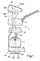
- the water mixer fitting 1 shown in FIG. 1 in a first preferred embodiment as a single lever mixer fitting can be explained quite well in its basic structure in connection with FIG. 2.
- the water mixing valve 1 initially has two water inlets 2 and two water inlet valves 3 assigned to the water inlets 2. 1 and 2, only one water inlet 2 and one water inlet valve 3 can be seen in each case.
- One of the water inlets 2 is connected to a hot water inlet, the other water inlet 2 is connected to a cold water inlet.
- the water inlet valves 3 are formed by the openings which can be brought into different overlaps in ceramic disks which can be moved onto one another. This technique has long been known as such and requires no further explanation here.
- a mixing chamber 4 is provided, which is on the one hand in connection with the water inlets 2, on the other hand, with a mixed water outlet 5, namely via a water outlet valve 6, in connection.
- the previously explained parts of the water mixer fitting 1 are combined in a cartridge 7 designed as a closed block.
- Fig. 1 shows that from the cartridge 7 protrudes only one actuating lever 8, with the aid of which a ceramic disc 9 shown in Fig. 2 above for opening and closing the water inlet valves 3 and the water outlet valve 6 is movable.
- a spacer and swivel ring 10 is placed on the cartridge 7, on which in turn an actuator 11 is then placed.
- the actuator 11 By means of the actuator 11, the water inlet valves 3 and the water outlet valve 6 are actuated via the actuating lever 8. Because of the design of the water mixing valve 1 as a lifting mixing valve, the actuator is a rotary and rocker arm. 2 shows a housing 12, which is not shown in FIG. 1.
- 3 shows the block diagram of an electronic temperature measuring circuit 13 with a temperature sensor 14 arranged in the mixed water outlet 5;
- the temperature sensor 14 can be seen schematically in FIG. 2, but in the block diagram according to FIG. 3 it is part of a temperature measuring block 15.
- Part of the temperature measuring block 15 in FIG. 3 is also a mixed temperature display 16.
- the temperature measuring circuit 13 initially has a battery 17 as the current source. 3 then shows that, according to the teaching of the invention, the temperature measuring circuit 13 has, in addition to the first current source designed as a battery 17, a solar cell 18 as a further current source. Circuitry measures, which are explained below, ensure that above a predetermined upper brightness limit value only the solar cell 18 is effective as a current source for the temperature measuring circuit 13, that below a predetermined average brightness limit value only the battery 17 is effective as a current source for the temperature measuring circuit 13 and that below a predetermined lower brightness limit, neither the solar cell 18 nor the battery 17 are effective as a current source for the temperature measuring circuit 13.
- the temperature measuring circuit 13 also includes an auxiliary switch 19 and two switching diodes 20, 21.
- the solar cell 18 is effective as a current source for the temperature measuring circuit 13, although the auxiliary switch 19 is closed. This is achieved in that the voltage of the solar cell 18 is greater than the voltage of the battery 17, so that although current can flow from the solar cell 18 via the switching diode 20 and the temperature measuring block 15, the switching diode 21 prevents current from the battery 17 can flow. The switching diode 21 naturally also prevents current from flowing from the solar cell 18 via the battery 17.
- the solar cell 18 and the battery 17 act as current sources for the temperature measuring circuit 13. This results from the current-voltage characteristics of solar cells.
- the battery 18 is effective as a current source for the temperature measuring circuit 13. This results from the fact that the voltage of the battery 17 is now greater than the voltage of the solar cell 18, so that the switching diode 20 prevents a current from flowing from the solar cell 18. The switching diode 20 prevents of course also that current flows from the battery 17 via the solar cell 18.
- the water mixer fitting 1 is exposed to a brightness which is below a predetermined lower brightness limit value, for example the illuminance is less than 5 lux, then neither the solar cell 18 nor the battery 17 are effective as a current source for the temperature measuring circuit 13. On the one hand, the voltage of the solar cell 18 is then insufficient, on the other hand, the auxiliary switch 19 is then opened, controlled by the solar cell 18, so that no current can flow from the battery 18.
- a predetermined lower brightness limit value for example the illuminance is less than 5 lux
- a battery 17 is provided as the first current source.
- the first current source could also be designed as an accumulator.
- a modification of the temperature measuring circuit 13 could then be expedient in such a way that the accumulator can be charged by the solar cell 18.
- the lamps known in the prior art can be used as the mixing temperature display 16.
- the mixed temperature display 16 corresponds to modern technology to design the mixed temperature display 16 as a liquid crystal number display or as a LED display.
- a liquid crystal numerical display has a lower power consumption, but requires additional lighting so that it can be read in the dark.
- a LED number display constantly has a slightly higher power consumption, but can also be read in the dark. It depends on the respective application, which of the two options you choose.
- a water mixer fitting according to the invention for bathtubs or the like can be designed in such a way that a target value is sensed at the temperature measuring circuit to sense the water level in the bathtub or the like.
- the water level-specifying water level sensor is connected and an acoustic warning signal, a switching signal or the like can be emitted by the temperature measuring circuit when the desired water level is reached.
- the temperature sensor 14 can be used in a ring surrounding the mixed water outlet 5, preferably arranged next to the mixing chamber 4.
- this ring is part of a sensor plate 24 having passages 22, 23 assigned to the water inlets 2 and the mixed water outlet 5.
- the sensor plate 24 acts as an intermediate layer between the cartridge 7 and the housing 12, so that little needs to be changed as such on the water mixer fitting 1.
- the dimensions of the sensor plate 24 must of course be matched to the dimensions of the corresponding water mixer fitting 1.
- a thickness of the sensor plate 24 of 4 to 7 mm, preferably a thickness of approximately 5.5 mm, and a diameter of approximately 48 mm have proven to be particularly suitable for the conventional single-lever mixer taps.
- both the inflowing water and the outflowing mixed water flow through the sensor plate 24, which therefore requires sealing against the cartridge 7 on the one hand and the housing 12 on the other hand.
- the seal against the cartridge 7 serve Usually on the underside of the cartridge 7, the water inlets 2 and the mixed water outlet 5 surrounding sealing rings.
- the sensor plate 24 is provided on the underside with receiving grooves 25 for the sealing rings 26 surrounding the passages 22, 23 according to the preferred teaching of the invention. Corresponding receiving grooves can of course also be provided on the upper side of the sensor plate 24 if this is expedient for design reasons. 5 to 7 show this particularly clearly.
- the sensor plate 24 has a receiving bore 27 for the temperature sensor 14 which extends radially to the passage 23 assigned to the mixed water outlet 5 and extends from the edge of the sensor plate 24 to the passage 23 and the temperature sensor 14 can be inserted sealingly into the receiving bore 27.
- the preferred embodiment shown in the drawing makes it clear that it is particularly useful if the temperature sensor 14 is provided with an external thread 28 and the receiving bore 27 with a corresponding internal thread 29 and that preferably between a circumferential sealing surface 30 on the temperature sensor 14 and a circumferential Sealing surface 31 in the receiving bore 27, a sealing element 32 is arranged.
- Fig. 7 shows clearly that the temperature sensor 14 is provided on the side facing the outer edge of the sensor plate 24 with a screwdriver slot 34 so that it can be screwed into the receiving bore 27 without further notice.
- Other forms of actuation are of course also conceivable here.
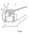
- Fig. 4 shows a special embodiment of the water mixer fitting 1 according to the invention, in which the sensor plate 24 carries an extension 35 which receives the temperature measuring circuit 13.
- the attachment part 35 is guided upward in an arc on the side facing away from the actuating end of the actuating member 11 and carries the mixed temperature display 16 at the upper end in a manner which is very clearly visible to an actuating person.
- the attachment part carries a jack for plugging in the mixing temperature.
- the mixed temperature display is separated from the attachment part, but can be plugged into the attachment part.
- FIG. 4 The embodiment of a water mixer fitting 1 according to the invention shown in FIG. 4 requires an adapted overall construction of the housing 12, in particular because of the extension 35 which is led out to the rear. It is of course particularly expedient if the overall construction of a water mixer fitting 1 can be maintained essentially without a temperature indicator. How this is possible is explained in detail below.
- Fig. 1 shows the water mixing temperature 1 in the embodiment as a single-lever mixer fitting, in which the actuator 11 carries a cover cap on the top in a manner known per se.
- this cover cap is designed as a desk-like attachment part 36 which receives the mixed temperature display 16 and is connected or connectable via lines 37 to the temperature sensor 14 or to the sensor plate 24. With the aid of snap-in connections 38, the attachment part 36 can be snapped onto the actuating member 11 practically in the same way as the cover cap otherwise used.
- other connection techniques are also possible here.
- the attachment part 36 has connector body 39 for detachable connection of the electrical lines 37.
- the connector body 39 are formed in the embodiment shown here as sockets; accordingly, the associated ends of the lines 37 are provided with plugs.
- Other configurations, for example as spring-loaded terminals or the like, are of course also conceivable for the connector body 39.
- the connector body 39 are, according to the preferred teaching of the invention, executed separately per line 37 and protected in a special way against moisture and splash water, so that between the connector bodies 39, d. H. the lines 37, can not form short-circuit bridges.
- the temperature measuring circuit 13 is arranged in the top part 36.
- the solar cell 18 is also arranged on the top of the top part 36. In the exemplary embodiment shown here, this is a solar cell group.
- the battery 17 is also indicated in a conventional clamped version.
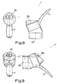
- Fig. 8 shows the water mixer fitting 1 in the arrangement and configuration for a sink.
- the direction of view of an actuating person is indicated here by a dashed line. It is essential that the top of the top part 36 through the wedge-shaped design of the attachment part 36 in the direction of the operator is suitable. In the application shown in FIG. 8, the forward inclination toward the actuating end of the actuating member 11 is selected.
- the realization of the inclination by the wedge-shaped design of the attachment part 36 has the advantage that this inclination can be changed by moving the attachment part 36.
- FIG. 9 shows the object from FIG. 8 with an implemented attachment part 36 in the arrangement on the wall of a shower cubicle. The operator's line of sight is indicated accordingly.
- the angle of inclination of the top of the attachment part 36 according to the preferred teaching of the invention when the actuator 11 is in the closed position is approximately 80 to 50 °, preferably approximately 70 °, based on the main axis 40 of the water mixer fitting 1 is.
- the attachment part 36 has an annular, upwardly open socket 41, which can preferably be snapped onto the actuating member 11, and an electronic module 42 which can be inserted sealingly into the socket 41.
- This electronics module 42 is sealed from the socket 41 by a circumferential sealing ring 43 and covered by a transparent plastic cap 44.
- Connection lines 45 lead from the electronics module 42 to the connection bodies 39.
Description
Die Erfindung betrifft eine Wassermischarmatur, insbesondere eine Einhebelmischarmatur, mit einerseits vorzugsweise zwei Wassereinlässen, zwei Wassereinlaßventilen, einer Mischkammer, einem Eischwasserauslaß, ggf. einem Wasserauslaßventil und mindestens einem Betätigungsorgan für die Wassereinlaßventile und ggf. das Wasserauslaßventil und mit andererseits einer elektronischen Temperaturmeßschaltung, wobei die Temperaturmeßschaltung einen im Mischwasserauslaß angeordneten Temperatursensor, eine Mischtemperaturanzeige und eine Stromquelle, z. B. eine Batterie oder einen Akkumulator, aufweist.The invention relates to a water mixer fitting, in particular a single-lever mixer fitting, with on the one hand preferably two water inlets, two water inlet valves, a mixing chamber, an ice water outlet, possibly a water outlet valve and at least one actuator for the water inlet valves and possibly the water outlet valve and with an electronic temperature measuring circuit, on the one hand, the Temperature measuring circuit arranged in the mixed water outlet temperature sensor, a mixed temperature display and a current source, for. B. has a battery or an accumulator.
Wassermischarmaturen der in Rede stehenden Art sind für Waschbecken, Badewannen, Duschen, Bidets usw. bekannt. Sie dienen generell zur Mischung von über die Wassereinlässe zuströmendem Wasser unterschiedlicher Temperatur - Kaltwasser und Heißwasser - zu am Mischwasserauslaß ausströmendem Mischwasser einer gewünschten Temperatur. Damit man feststellen kann, wie hoch die Temperatur des Mischwassers ist, um sich beispielsweise nicht an zu heißem Wasser zu verbrühen, weisen die Wassermischarmaturen der Art, von der die Erfindung ausgeht, eine Temperaturmeßschaltung auf, zu der dann insbesondere auch eine Mischtemperaturanzeige gehört.Water mixer taps of the type in question are known for wash basins, bathtubs, showers, bidets, etc. They are generally used to mix water of different temperatures - cold water and hot water - flowing in via the water inlets to mixed water of a desired temperature flowing out at the mixed water outlet. So that you can determine how high the temperature of the mixed water is, for example not to scald yourself with water that is too hot, the water mixer taps of the type from which the invention is based have a temperature measuring circuit, which then also includes a mixed temperature display.
Im übrigen gilt generell, daß bei Wassermischarmaturen der in Rede stehenden Art früher durchweg jedem Wassereinlaßventil ein eigenes Betätigungsorgan in Form eines Regelhandgriffes zugeordnet war, daß aber heutzutage zunehmend Einhebelmischarmaturen Verwendung finden. Bei Einhebelmischarmaturen werden zumeist durch Drehung und Kippung eines einzigen Betätigungsorgans in Form eines Dreh- und Kipphebels die Wassereinlaßventile zur Erzielung der gewünschten Mischung und der gewünschten Menge eingestellt. Das Betätigungsorgan kann auch, statt als Dreh- und Kipphebel, als Dreh- und Schiebehebel ausgeführt sein.Incidentally, it generally applies that in the case of water mixer taps of the type in question, each water inlet valve was previously assigned its own actuating element in the form of a control handle, but that single lever mixer taps are increasingly being used today. In single-lever mixer taps, the water inlet valves are usually adjusted to achieve the desired mixture and the desired quantity by rotating and tilting a single actuating element in the form of a rotary and rocking lever. The actuator can also be designed as a rotary and slide lever instead of as a rotary and rocker arm.
Die bekannte Wassermischarmatur, von der die Erfindung ausgeht, ist sowohl als klassische Wassermischarmatur mit zwei Betätigungsorganen als auch als moderne Einhebelmischarmatur mit nur einem Betätigungsorgan bekannt (vgl. die DE-A-3 045 531, und zwar einerseits die Fig. 1 bis 4, andererseits die Fig. 7 und 8).The known water mixer tap, from which the invention is based, is known both as a classic water mixer tap with two actuating members and as a modern single-lever mixer tap with only one actuating member (cf. DE-A-3 045 531, on the one hand FIGS. 1 to 4, on the other hand, FIGS. 7 and 8).
Dabei ragt der Temperatursensor, der hier als Widerstandsmeßfühler ausgeführt ist, in das freie Ende des Mischwasserauslasses hinein. Der Temperatursensor ist mit Verbindungsleitungen mit der übrigen Temperaturmeßschaltung verbunden, die an der Rückseite der Wassermischarmatur angeordnet ist. Die Temperaturmeßschaltung weist eine Brückenschaltung auf, mit der der Sollwert der Temperatur des Mischwassers eingestellt werden kann. Jedem der Wassereinlaßventile bzw. der entsprechenden Betätigungsorgane zugeordnet bzw. auf den entsprechenden Seiten des einen Betätigungsorgans angeordnet sind optische Anzeigeelemente, vorzugsweise farbige Lämpchen, die eine Aussage über die Temperatur des Mischwassers machen. Je nach dem, ob der Sollwert der Temperatur des Mischwassers überschritten oder unterschritten ist, leuchtet das optische Anzeigeelement auf, dessen zugeordnetes Wassereinlaßventil einer Änderung der Einstellung bedarf.The temperature sensor, which is designed here as a resistance sensor, projects into the free end of the mixed water outlet. The temperature sensor is connected with connecting lines to the rest of the temperature measuring circuit, which is arranged at the rear of the water mixer fitting. The temperature measuring circuit has a bridge circuit with which the setpoint of the temperature of the mixed water can be set. Associated with each of the water inlet valves or the corresponding actuating elements or arranged on the corresponding sides of the one actuating element are optical display elements, preferably colored lamps, which provide information about the temperature of the mixed water. Depending on whether the setpoint temperature of the mixed water has been exceeded or fallen below, the optical display element lights up, the associated water inlet valve of which requires a change in the setting.
Bei der bekannten, zuvor beschriebenen Wassermischarmatur weist die Temperaturmeßschaltung als Stromquelle eine Batterie oder einen Akkumulator auf. (Batterie steht hier und im folgenden immer für ein Primärelement, das nicht aufladbar ist, während Akkumulator hier und im folgenden immer für ein Sekundärelement steht, das wieder aufladbar ist). Um den Stromverbrauch so gering wie möglich zu halten, wird zumindest die Mischtemperaturanzeige als größter Stromverbraucher, unter Umständen aber auch die Temperaturmeßschaltung insgesamt, nur eingeschaltet, wenn die Wassermischarmatur in Betrieb ist. Dieses Einschalten erfolgt mittels eines die Strömung am Mischwasserauslaß erfassenden Strömungsfühlers (vgl. Fig. 1 der DE-A-3 045 531). Nur bei einer ausreichenden Strömung ist also die Temperaturmeßschaltung mit der Mischtemperaturanzeige aktiviert.In the known, previously described water mixer fitting, the temperature measuring circuit has a battery or an accumulator as the current source. (The battery here and below always stands for a primary element that cannot be recharged, while the battery here and below always stands for a secondary element that can be recharged). In order to keep the electricity consumption as low as possible, at least the mixed temperature display as the largest electricity consumer, but possibly also the temperature measuring circuit as a whole, is only switched on when the water mixer tap is in operation. This switching on takes place by means of a flow sensor which detects the flow at the mixed water outlet (cf. FIG. 1 of DE-A-3 045 531). The temperature measurement circuit with the mixed temperature display is only activated if there is sufficient flow.
Im übrigen ist es bei einer der zuvor erläuterten Wassermischarmatur entsprechenden Wassermischarmatur bekannt, zum Einschalten und Ausschalten der Temperaturmeßschaltung jedem Betätigungsorgan einen elektromechanischen, die Stellung des Betätigungsorgans abtastenden Schalter zuzuordnen (vgl. die US-A-4406 398), so daß eine Aktivierung der Temperaturmeßschaltung überhaupt nur dann erfolgt wenn das Betätigungsorgan bzw. zumindest ein Betätigungsorgan in Öffnungsrichtung betätigt wird.In addition, it is known in a water mixer fitting corresponding to the previously explained water mixer fitting to assign an electromechanical switch, which senses the position of the actuating element, to switch the temperature measuring circuit on and off (see US Pat. No. 4,406,398), so that the temperature measuring circuit is activated only occurs if the actuating member or at least one actuating member is actuated in the opening direction.
Die eingangs erläuterte Wassermischarmatur, von der die Erfindung ausgeht, erfordert trotz der vorgesehenen Stromsparmaßnahmen ein häufiges Wechseln der Batterie bzw. ein häufiges Aufladen des Akkumulators. Die Konstruktion insgesamt erfordert relativ weitgehende Änderungen an der Wassermischarmatur, unter anderem im Bereich des Mischwasserauslasses und die mit der Mischtemperaturanzeige dieser Wassermischarmatur gewonnene Information ist für normale Anwendungsfälle nicht besonders geeignet. Insgesamt ist also die eingangs erläuterte bekannte Wassermischarmatur für eine weite Verbreitung in der Praxis nicht geeignet.The water mixer fitting explained at the beginning, from which the invention is based, requires frequent replacement of the battery or frequent recharging of the rechargeable battery despite the envisaged power saving measures. The overall design requires relatively extensive changes to the water mixing valve, including in the area of the mixed water outlet, and the information obtained with the mixing temperature display of this water mixing valve is not particularly suitable for normal applications. Overall, the known water mixer fitting explained at the outset is therefore unsuitable for widespread use in practice.
Der Erfindung liegt nun die Aufgabe zugrunde, eine Wassermischarmatur mit einer elektronischen Temperaturmeßschaltung anzugeben, die den praktischen Anforderungen in elektronischschaltungstechnischer, mechanisch-konstruktiver und anwendungstechnischer Hinsicht optimal entspricht, insbesondere, aber nicht nur, unter Berücksichtigung der besonderen Gegebenheiten bei Einhebelmischarmaturen.The invention is based on the object of specifying a water mixer fitting with an electronic temperature measurement circuit which meets the practical requirements corresponds optimally in terms of electronic circuit technology, mechanical design and application technology, especially, but not only, taking into account the special circumstances of single-lever mixer taps.
Die erfindungsgemäße Wassermischarmatur, bei der die zuvor aufgezeigte Aufgabe gelöst ist, ist nun zunächst und im wesentlichen dadurch gekennzeichnet, daß die Temperaturmeßschaltung zusätzlich zu der als Batterie oder Akkumulator ausgeführten ersten Stromquelle eine Solarzelle oder mehrere Solarzellen als weitere Stromquelle aufweist und oberhalb eines vorgegebenen oberen Helligkeitsgrenzwertes nur die Solarzelle als Stromquelle für die Temperaturießschaltung wirksam ist. Vorzugsweise ist zusätzlich dafür gesorgt, daß unterhalb eines vorgegebenen mittleren Helligkeitsgrenzwertes nur die Batterie bzw. der Akkumulator als Stromquelle für die Temperaturmeßschaltung wirksam ist und/oder daß unterhalb eines vorgegebenen unteren Helligkeitsgrenzwertes weder die Solarzelle noch die Batterie bzw. der Akkumulator als Stromquelle für die Temperaturmeßschaltung wirksam sind.The water mixer fitting according to the invention, in which the above-mentioned object is achieved, is first and essentially characterized in that the temperature measuring circuit has, in addition to the first current source embodied as a battery or accumulator, a solar cell or several solar cells as a further current source and above a predetermined upper brightness limit value only the solar cell is effective as a current source for the temperature control circuit. Preferably, it is additionally ensured that only the battery or the accumulator acts as a current source for the temperature measurement circuit below a predetermined average brightness limit value and / or that neither the solar cell nor the battery or the accumulator acts as a current source for the temperature measurement circuit below a predetermined lower brightness limit value are effective.
Der wesentliche Erfindungsgedanke ist also der, als Stromquelle für die Temperaturmeßschaltung zusätzlich zu der Batterie oder dem Akkumulator noch eine Solarzelle oder mehrere Solarzellen vorzusehen und dafür Sorge zu tragen, daß oberhalb eines vorgegebenen oberen Helligkeitsgrenzwertes, wenn es also hinreichend hell ist, nur die Solarzelle bzw. die Solarzellen als Stromquelle für die Temperaturmeßschaltung wirksam ist. Ist ergänzend realisiert, daß unterhalb eines vorgegebenen mittleren Helligkeitsgrenzwertes nur die Batterie bzw. der Akkumulator als Stromquelle für die Temperaturmeßschaltung wirksam ist und unterhalb eines vorgegebenen unteren Helligkeitsgrenzwertes weder die Solarzelle noch die Batterie bzw. der Akkumulator als Stromquelle für die Temperatumeßschaltung wirksam sind, so wird insgesamt ein minimaler Stromverbrauch erreicht. Oberhalb eines vorgegebenen oberen Helligkeitsgrenzwertes, wenn es also hinreichend hell ist, arbeitet die Temperaturmeßschaltung, ohne die Batterie bzw den Akkumulator zu belasten. Unterhalb eines Vorgegebenen mittleren Helligkeitsgrenzwertes und oberhalb eines vorgegebenen unteren Helligkeitsgrenzwertes, wenn es nicht mehr hinreichend hell für die Solarzelle bzw. die Solarzellen ist, gleichwohl noch eine Inbetriebnahme der Wassermischarmatur möglich ist, dient nur die Batterie bzw. der Akkumulator als Stromquelle für die Temperaturmeßschaltung, aber eben dann und nur dann, wenn die Helligkeit unterhalb des mittleren Helligkeitsgrenzwertes und oberhalb des unteren Helligkeitsgrenzwertes liegt. Liegt die Helligkeit unterhalb des unteren Helligkeitsgrenzwertes, so gilt, daß einerseits die Solarzelle bzw. die Solarzellen nicht mehr als Stromquelle für die Temperaturmeßschaltung dienen können, daß andererseits die Batterie bzw. der Akkumulator nicht mehr als Stromquelle für die Temperaturmeßschaltung dienen soll.The main idea of the invention is therefore to provide a solar cell or several solar cells as a current source for the temperature measuring circuit in addition to the battery or the accumulator and to ensure that above a predetermined upper brightness limit value, if it is sufficiently bright, only the solar cell or the solar cells are effective as a current source for the temperature measuring circuit. If it is additionally realized that only the battery or the accumulator is effective as a current source for the temperature measuring circuit below a predetermined average brightness limit value and that neither the solar cell nor the battery or the accumulator are effective as a current source for the temperature measuring circuit below a predetermined lower brightness limit value overall minimal power consumption achieved. Above a predetermined upper brightness limit value, that is if it is sufficiently bright, the temperature measuring circuit works without loading the battery or the accumulator. Below a specified average brightness limit value and above a specified lower brightness limit value when it is no longer sufficiently bright for the solar cell or solar cells, although commissioning of the water mixer fitting is still possible, only the battery or the accumulator serves as a current source for the temperature measurement circuit, but only then and only if the brightness is below the average brightness limit value and above the lower brightness limit value. If the brightness is below the lower brightness limit value, then it applies that on the one hand the solar cell or the solar cells can no longer serve as a current source for the temperature measurement circuit, and on the other hand the battery or the accumulator should no longer serve as a current source for the temperature measurement circuit.
Es gibt nun eine Vielzahl von Möglichkeiten, die erfindungsgemäße Wassermischarmatur auszugestalten und weiterzubilden, was im folgenden anhand einer lediglich Ausführungsbeispiele darstellenden Zeichnung weiter erläutert wird; es zeigen
- Fig. 1 in einer schematischen Sprengdarstellung ein erstes bevorzugtes Ausführungsbeispiel einer erfindungsqemäßen Wassermischarmatur in der Ausführungsform als Einhebelmischarmatur,
- Fig. 2 im Schnitt, ausschnittweise, stark vergrößert, den unteren Teil einer Kartusche einer Wassermischarmatur gemäß Fig. 1,
- Fig. 3 ein Blockschaltbild der Temperaturmeßschaltung der Wassermischarmatur nach Fig. 1,
- Fig. 4 in schematischer Darstellung ein weiteres Ausführungsbeispiel einer erfindungsgemäßen Wassermischarmatur in der Ausführungsform als Einhebelmischarmatur,
- Fig. 5 in detaillierter Darstellung eine Sensorplatte für eine Wassermischarmatur gemäß den Fig. 1 bzw. 4,
- Fig. 6 den Gegenstand nach Fig. 5 im Schnitt entlang der Linie VI - VI,
- Fig. 7 den Gegenstand nach Fig. 5 vergrößert und im Schnitt entlang der Linie VII - VII mit eingesetztem Temperatursensor,
- Fig. 8 den Gegenstand nach Fig. 1, zusammengesetzt und angewandt für ein Waschbecken,
- Fig. 9 den Gegenstand nach Fig. 1, zusammengesetzt und angewandt für eine Badewanne oder eine Dusche, und
- Fig. 10 in stark vergrößerter Darstellung ein Aufsatzteil für eine Wassermischarmatur gemäß Fig. 1.
- 1 is a schematic exploded view of a first preferred embodiment of a water mixer fitting according to the invention in the embodiment as a single lever mixer fitting,
- 2 in section, detail, greatly enlarged, the lower part of a cartridge of a water mixer fitting according to FIG. 1,
- 3 is a block diagram of the temperature measuring circuit of the water mixing valve according to FIG. 1,
- 4 shows a schematic representation of a further exemplary embodiment of a water mixer fitting according to the invention in the embodiment as a single lever mixer fitting,
- 5 in a detailed representation a sensor plate for a water mixer fitting according to FIGS. 1 and 4,
- 5 in section along the line VI - VI,
- 5 enlarged and in section along the line VII - VII with inserted temperature sensor,
- 8 shows the object according to FIG. 1, assembled and used for a sink,
- Fig. 9 shows the subject of Fig. 1, assembled and applied for a bath or shower, and
- 10 shows a greatly enlarged illustration of an attachment part for a water mixer fitting according to FIG. 1.
Die Lehre der Erfindung befaßt sich allgemein mit Wassermischarmaturen und wird nachfolgend nur der Einfachheit halber anhand von Ausführdngsbeispielen von Einhebelmischarmaturen erläutert. Eine Vielzahl von Aspekten der Lehre der Erfindung sind aber in entsprechender Weise auch bei Wassermischarmaturen mit zwei Betätigungsorganen zu verwirklichen. Auch kann die Lehre der Erfindung bei Wasserarmaturen angewendet werden, denen bereits Mischwasser bzw. erwärmtes Wasser zugeführt wird. Weiter kann die Lehre der Erfindung aber auch bei für andere Zwecke eingesetzten Temperaturmeßschaltungen, z. B. für Raumtemperaturanzeigen, auch in Verbindung mit Uhren, für Körperthermometer, für Thermoflaschen, für Babyflaschen usw., angewendet werden. Die erfindungsgemäße Art der Stromversorgung einer Temperaturmeßschaltung kann schließlich ohne weiteres auch auf andere Meßschaltungen übertragen werden, z. B. auf Meßschaltungen für Barometer und Hygrometer.The teaching of the invention is generally concerned with water mixer taps and is only explained for the sake of simplicity on the basis of exemplary embodiments of single lever mixer taps. However, a large number of aspects of the teaching of the invention can also be implemented in a corresponding manner in water mixer taps with two actuating members. The teaching of the invention can also be applied to water fittings to which mixed water or heated water is already supplied. Furthermore, the teaching of the invention can also be used for temperature measurement circuits used for other purposes, e.g. B. for room temperature displays, also in connection with watches, for body thermometers, for thermo bottles, for baby bottles, etc., are used. The type of power supply of a temperature measuring circuit according to the invention can finally be easily transferred to other measuring circuits, z. B. on measuring circuits for barometers and hygrometers.
Die in Fig. 1 in einem ersten bevorzugten Ausführungsbeispiel als Einhebelmischarmatur dargestellte Wassermischarmatur 1 läßt sich in ihrem grundsätzlichen Aufbau in Verbindung mit Fig. 2 recht gut erläutern. Die Wassermischarmatur 1 weist zunächst zwei Wassereinlässe 2 und zwei den Wassereinlässen 2 zugeordnete Wassereinlaßventile 3 auf. In den Fig. 1 und 2 ist jeweils nur ein Wassereinlaß 2 und ein Wassereinlaßventil 3 zu erkennen. Einer der Wassereinlässe 2 ist an einen Heißwasserzulauf angeschlossen, der andere Wassereinlaß 2 ist an einen Kaltwasserzulauf angeschlossen. Die Wassereinlaßventile 3 werden im hier dargestellten Ausführungsbeispiel einer Einhebelmischarmatur von den in unterschiedliche Überdeckung bringbaren Öffnungen in aufeinander verschiebbaren Keramikscheiben gebildet. Diese Technik ist seit langem als solche bekannt und bedarf hier keiner Weiteren Erläuterung.The water mixer fitting 1 shown in FIG. 1 in a first preferred embodiment as a single lever mixer fitting can be explained quite well in its basic structure in connection with FIG. 2. The water mixing valve 1 initially has two
In Fig. 2 ist gut zu erkennen, daß eine Mischkammer 4 vorgesehen ist, die einerseits mit den Wassereinlässen 2 in Verbindung steht, mit der andererseits ein Mischwasserauslaß 5, und zwar über ein Wasserauslaßventil 6, in Verbindung steht. Die zuvor erläuterten Teile der Wassermischarmatur 1 sind in einer als geschlossener Block ausgebildeten Kartusche 7 zusammengefaßt. Fig. 1 zeigt, daß von der Kartusche 7 nach oben nur ein Betätigungshebel 8 herausragt, mit dessen Hilfe eine in Fig. 2 oben dargestellte Keramikscheibe 9 zum Öffnen und Schließen der Wassereinlaßventile 3 und des Wasserauslaßventils 6 bewegbar ist. Auf die Kartusche 7 ist ein Abstands und Schwenkring 10 aufgesetzt, auf den seinerseits dann ein Betätigungsorgan 11 aufgesetzt ist. Mittels des Betätigungsorgans 11 werden über den Betätigungshebel 8 die Wassereinlaßventile 3 und das Wasserauslaßventil 6 betätigt. Wegen der Ausführung der Wassermischarmatur 1 als Einhebeimischarmatur ist das Betätigungsorgan hier ein Dreh- und Kipphebel. Fig. 2 zeigt im übrigen noch angedeutet ein Gehäuse 12, das in Fig. 1 nicht dargestellt ist.In Fig. 2 it can be clearly seen that a mixing chamber 4 is provided, which is on the one hand in connection with the
Unter Heranziehung von Fig. 3 kann nun auch die elektronisch-schaltungstechniche Seite der Wassermischarmatur 1 erläutert werden. Fig. 3 zeigt das Blockschaltbild einer elektronischen Temperaturmeßschaltung 13 mit einem im Mischwasserauslaß 5 angeordneten Temperatursensor 14; der Temperatursensor 14 ist schematisch in Fig. 2 zu erkennen, im Blockschaltbild nach Fig. 3 jedoch Teil eines Temperaturmeßblocks 15. Teil des Temperaturmeßblocks 15 in Fig. 3 ist auch eine Mischtemperaturanzeige 16.3, the electronic circuitry side of the water mixer fitting 1 can now also be explained. 3 shows the block diagram of an electronic
Fig. 3 läßt gut erkennen, daß die Temperaturmeßschaltung 13 als Stromquelle zunächst eine Batterie 17 aufweist. Weiter zeigt dann die Fig. 3, daß nach der Lehre der Erfindung die Temperaturmeßschaltung 13 zusätzlich zu der als Batterie 17 ausgeführten ersten Stromquelle eine Solarzelle 18 als weitere Stromquelle aufweist. Durch schaltungstechnische Maßnahmen, die weiter unten erläutert werden, ist sichergestellt, daß oberhalb eines vorgegebenen oberen Helligkeitsgrenzwertes nur die Solarzelle 18 als Stromquelle für die Temperaturmeßschaltung 13 wirksam ist, daß unterhalb eines vorgegebenen mittleren Helligkeitsgrenzwertes nur die Batterie 17 als Stromquelle für die Temperaturmeßschaltung 13 wirksam ist und daß unterhalb eines vorgegebenen unteren Helligkeitsgrenzwertes weder die Solarzelle 18 noch die Batterie 17 als Stromquelle für die Temperaturmeßschaltung 13 wirksam sind.3 clearly shows that the
Wie die Fig. 3 weiter zeigt, gehören im dargestellten Ausführungsbeispiel zu der Temperaturmeßschaltung 13 noch ein Hilfsschalter 19 sowie zwei Schaltdioden 20, 21.As FIG. 3 further shows, in the exemplary embodiment shown, the
Liegt die Helligkeit, der die erfindungsgemäße Wassermischarmatur 1 ausgesetzt ist, oberhalb eines vorgegebenen oberen Helligkeitsgrenzwertes, so ist nur die Solarzelle 18 als Stromquelle für die Temperaturmeßschaltung 13 wirksam, obwohl der Hilfsschalter 19 geschlossen ist. Dies ist dadurch erreicht, daß die Spannung der Solarzelle 18 größer ist als die Spannung der Batterie 17, so daß zwar von der Solarzelle 18 Strom über die Schaltdiode 20 und den Temperaturmeßblock 15 fließen kann, die Schaltdiode 21 jedoch verhindert, daß Strom von der Batterie 17 fließen kann. Die Schaltdiode 21 verhindert natürlich auch, daß Strom von der Solarzelle 18 über die Batterie 17 fließen kann.If the brightness to which the water mixer fitting 1 according to the invention is exposed lies above a predetermined upper brightness limit value, only the
Wenn die Helligkeit, der die Wassermischarmatur 1 ausgesetzt ist, unterhalb eines vorgegebenen oberen Helligkeitsgrenzwertes, aber oberhalb eines vorgegebenen mittleren Helligkeitsgrenzwertes liegt, so sind die Solarzelle 18 und die Batterie 17 als Stromquellen für die Temperaturmeßschaltung 13 wirksam. Das resultiert aus den Strom-Spannungs-Kennlinien von Solarzellen.If the brightness to which the water mixer fitting 1 is exposed is below a predetermined upper brightness limit value, but above a predetermined average brightness limit value, the
Liegt nun die Helligkeit, der die Wassermischarmatur 1 ausgesetzt ist, unterhalb eines vorgegebenen mittleren Helligkeitsgrenzwertes, so ist nur die Batterie 18 als Stromquelle für die Temperaturmeßschaltung 13 wirksam. Das resultiert daraus, daß nunmehr die Spannung der Batterie 17 größer ist als die Spannung der Solarzelle 18, so daß die Schaltdiode 20 verhindert, daß von der Solarzelle 18 ein Strom fließt. Die Schaltdiode 20 verhindert natürlich auch, daß von der Batterie 17 Strom über die Solarzelle 18 fließt.If the brightness to which the water mixer fitting 1 is exposed now lies below a predetermined average brightness limit value, only the
Das, was zuvor beschrieben worden ist, gilt in Strenge nur, wenn die Schaltdioden 20, 21 "ideale Schalter" wären, was sie jedoch nicht sind. Tatsächlich erfolgt deshalb dann, wenn die Helligkeit den mittleren Helligkeitsgrenzwert unterschreitet, nicht schlagartig die Stromversorgung der Temperaturmeßschaltung 13 ausschließlich durch die Batterie 18, vielmehr gibt es einen Übergangsbereich, in dem auch noch die Solarzelle 18 als Stromquelle für die Temperaturmeßschaltung 13 wirksam ist. Entsprechendes gilt auch umgekehrt, d. h. dann, wenn die Helligkeit den oberen Helligkeitsgrenzwert - von unten kommend - überschreitet.What has been described above applies strictly only if the switching
Wenn die Wassermischarmatur 1 einer Helligkeit ausgesetzt ist, die unterhalb eines vorgegebenen unteren Helligkeitsgrenzwertes liegt, die Beleuchtungsstärke beispielsweise kleiner als 5 lux ist, dann sind weder die Solarzelle 18 noch die Batterie 17 als Stromquelle für die Temperaturmeßschaltung 13 wirksam. Einerseits reicht nämlich dann die Spannung der Solarzelle 18 nicht aus, andererseits ist dann, gesteuert von der Solarzelle 18, der Hilfsschalter 19 geöffnet, so daß von der Batterie 18 kein Strom fließen kann.If the water mixer fitting 1 is exposed to a brightness which is below a predetermined lower brightness limit value, for example the illuminance is less than 5 lux, then neither the
Die vorstehenden Erläuterungen zu der schaltungstechnischen Ausgestaltung der erfindungsgemäßen Wassermischarmatur 1 sind unabhängig davon, ob im übrigen bei Nichtgebrauch der Wassermischarmatur 1 eine anderweitige Ausschaltung der Temperaturmeßschaltung 13 erfolgt. Im Stand der Technik von dem die Erfindung ausgeht, ist für diese Funktion ein Strömungsfühler dem Mischwasserauslaß 5 zugeordnet. Das ist eine aufwendige Lösung. Eine weitere Lehre der Erfindung, der besondere und eigenständige Bedeutung zukommt, geht daher dahin, daß ein die Temperaturmeßschaltung insgesamt ein- und ausschaltender, die Stellung der Wassereinlaßventile 3 und/oder des Wasserauslaßventils 6 und/oder des Betätigungsorgans 11 abtastender, elektromechanischer Hauptschalter vorgesehen ist. In der bevorzugten Ausführungsform als Einhebelmischarmatur, die in den Figuren dargestellt ist, tastet der Hauptschalter zweckmäßigerweise die Kippstellung des als Betätigungsorgan 11 dienenden Dreh- und Kipphebels ab. Damit ist auf sehr einfache Weise sichergestellt, daß Strom wirklich nur dann verbraucht wird, wenn dies auch nötig ist, wenn also am Mischwasserauslaß 5 überhaupt eine Mischwassertemperatur zu messen ist.The above explanations regarding the circuit design of the water mixing valve 1 according to the invention are independent of whether the
In in Fig. 3 dargestellten Ausführungsbeispiel der Temperaturmeßschaltung 13 einer erfindungsgemäßen Wassermischarmatur 1 ist als erste Stromquelle eine Batterie 17 vorgesehen. Statt dessen könnte die erste Stromquelle auch als Akkumulator ausgeführt sein. Dann könnte eine Abwandlung der Temperaturmeßschaltung 13 dahingehend zweckmäßig sein, daß der Akkumulator von der Solarzelle 18 aufgeladen werden kann.In the embodiment of the
Grundsätzlich kommen bei der erfindungsgemäßen Wassermischarmatur 1 als Mischtemperaturanzeige 16 die im Stand der Technik bekannten Lämpchen in Frage. Moderner Technik entspricht es jedoch, die Mischtemperaturanzeige 16 als Flüssigkristall-Ziffernanzeige oder als Leuchtdioden-Ziffernanzeige auszubilden. Eine Flüssigkristall-Ziffernanzeige hat einen geringeren Stromverbrauch, bedarf aber einer zusätzlichen Beleuchtung, um bei Dunkelheit abgelesen werden zu können. Eine Leuchtdioden-Ziffernanzeige hat dauernd einen etwas höheren Stromverbrauch, kann aber zwang los auch im Dunkeln abgelesen werden. Es hängt vom jeweiligen Anwendungsfall ab, welche der beiden Möglichkeiten man wählt.Basically, in the water mixing valve 1 according to the invention, the lamps known in the prior art can be used as the mixing
Nach einer weiteren Lehre der Erfindung, der besondere und eigenständige Bedeutung zukommt, kann eine Wassermischarmatur gemäß der Erfindung für Badewannen od. dgl. dadurch besonders ausgestaltet sein, daß an die Temperaturmeßschaltung ein den Wasserstand in der Badewanne od. dgl. abtastender, einen Soll-Wasserstand vorgebender Wasserstandssensor angeschlossen und von der Temperaturmeßschaltung bei Erreichen des Soll-Wasserstands ein akustisches Warnsignal, ein Schaltsignal od. dgl. abgebbar ist.According to a further teaching of the invention, which is of particular and independent importance, a water mixer fitting according to the invention for bathtubs or the like can be designed in such a way that a target value is sensed at the temperature measuring circuit to sense the water level in the bathtub or the like. The water level-specifying water level sensor is connected and an acoustic warning signal, a switching signal or the like can be emitted by the temperature measuring circuit when the desired water level is reached.
Generell gilt für Wassermischarmaturen 1 der erfindungsgemäßen Art, also keineswegs nur für Einhebelmischarmaturen, daß der Temperatursensor 14 in einem den Mischwasserauslaß 5 umgebenden, vorzugsweise nächst der Mischkammer 4 angeordneten Ring eingesetzt sein kann. In der Ausführung als Einhebelmischarmatur empfiehlt sich dabei eine Ausgestaltung, bei der dieser Ring Teil einer den Wassereinlässen 2 und dem Mischwasserauslaß 5 zugeordnete Durchtritte 22, 23 aufweisenden Sensorplatte 24 ist. Die Sensorplatte 24 wirkt bei einer Einhebelmischarmatur gewissermaßen als Zwischenlage zwischen der Kartusche 7 und dem Gehäuse 12, so daß an sich an der Wassermischarmatur 1 als solcher besonders wenig geändert werden muß. Die Abmessungen der Sensorplatte 24 müssen natürlich auf die Abmessungen der entsprechenden Wassermischarmatur 1 abgestimmt werden. Für die üblichen Einhebelmischarmaturen hat sich eine Dicke der Sensorplatte 24 von 4 bis 7 mm, vorzugsweise eine Dicke von ca. 5,5 mm, und ein Durchmesser von ca. 48 mm als besonders passend erwiesen.In general, for water mixer taps 1 of the type according to the invention, and in no way only for single lever mixer taps, the
Wie die voranstehenden Erläuterungen deutlich machen, durch strömt sowohl das einströmende Wasser als auch das ausströmende Mischwasser die Sensorplatte 24, die also der Abdichtung gegenüber der Kartusche 7 einerseits und dem Gehäuse 12 andererseits bedarf. Der Abdichtung gegenüber der Kartusche 7 dienen üblicherweise an der Unterseite der Kartusche 7 die Wassereinlässe 2 und den Mischwasserauslaß 5 umgebende Dichtringe. Für die Abdichtung gegenüber dem Gehäuse 12 ist die Sensorplatte 24 nach bevorzugter Lehre der Erfindung auf der Unterseite mit die Durchtritte 22, 23 umgebenden Aufnahmenuten 25 für Dichtringe 26 versehen. Natürlich können entsprechende Aufnahmenuten auch auf der Oberseite der Sensorplatte 24 vorgesehen sein, wenn dies aus konstruktiven Gründen zweckmäßig ist. Das zeigen die Fig. 5 bis 7 besonders deutlich. Die Fig. 5 bis 7 zeigen ferner, daß es besonders zweckmäßig ist, wenn die Sensorplatte 24 eine radial zu dem dem Mischwasserauslaß 5 zugeordneten Durchtritt 23 verlaufende, vom Rand der Sensorplatte 24 bis in den Durchtritt 23 reichende Aufnahmebohrung 27 für den Temperatursensor 14 aufweist und der Temperatursensor 14 in die Aufnahmebohrung 27 abdichtend einsetzbar ist. Das in der Zeichnung dargestellte bevorzugte Ausführungsbeispiel macht dabei deutlich, daß es besonders zweckmäßig ist, wenn der Temperatursensor 14 mit einem Außengewinde 28 und die Aufnahmebohrung 27 mit einem entsprechenden Innengewinde 29 versehen sind und daß vorzugsweise zwischen einer umlaufenden Dichtfläche 30 am Temperatursensor 14 und einer umlaufenden Dichtfläche 31 in der Aufnahmebohrung 27 ein Dichtelement 32 angeordnet ist.As the above explanations make clear, both the inflowing water and the outflowing mixed water flow through the
In den Fig. 5 und 6 ist noch erkennbar, daß Durchgangsbohrungen 33 für Befestigungsschrauben vorgesehen sind, und zwar für Befestigungsschrauben, die an sich der Befestigung der Kartusche 7 im Gehäuse 12 dienen. Fig. 7 läßt gut erkennen, daß der Temperatursensor 14 auf der den Außenrand der Sensorplatte 24 zugewandten Seite mit einem Schraubendreherschlitz 34 versehen ist, so daß er ohne weiteres in die Aufnahmebohrung 27 eingeschraubt werden kann. Auch andere Betätigungsausformungen sind hier natürlich denkbar.5 and 6 it can still be seen that through
Fig. 4 läßt ein besonderes Ausführungsbeispiel der erfindungsgemäßen Wassermischarmatur 1 erkennen, bei dem nämlich die Sensorplatte 24 einen Ansatzteil 35 trägt, der die Temperaturmeßschaltung 13 aufnimmt. Im hier dargestellten Ausführungsbeispiel ist der Ansatzteil 35 auf der von dem Betätigungsende des Betätigungsorgans 11 abgewandten Seite bogenförmig nach oben geführt und trägt am oberen Ende die Mischtemperaturanzeige 16 in einer für eine betätigende Person sehr gut sichtbaren Weise. Eine Alternative zu dieser Ausführungsform, die zeichnerisch nicht dargestellt ist, besteht darin, daß der Ansatzteil eine Steckfassung zum Aufstecken der Mischtemperaturanzeigt trägt. Hierbei ist die Mischtemperaturanzeige von Ansatzteil getrennt, jedoch mit dem Ansatzteil steckbar verbindbar.Fig. 4 shows a special embodiment of the water mixer fitting 1 according to the invention, in which the
Das in Fig. 4 dargestellte Ausführungsbeispiel einer erfindungsgemäßen Wassermischarmatur 1 bedarf einer angepaßten Gesamtkonstruktion des Gehäuses 12, insbesondere wegen des nach hinten herausgeführten Ansatzteils 35. Besonders zweckmäßig ist es naturlich, wenn die Gesamtkonstruktion einer Wassermischarmatur 1 ohne Mischtemperaturanzeige im wesentlichen beibehalten werden kann. Wie das möglich ist, wird nachfolgend im einzelnen erläutert.The embodiment of a water mixer fitting 1 according to the invention shown in FIG. 4 requires an adapted overall construction of the
Fig. 1 zeigt die Wassermischtemperatur 1 in der Ausführungsform als Einhebelmischarmatur, bei der das Betätigungsorgan 11 in an sich bekannter Weise auf der Oberseite eine Abdeckkappe trägt. Nach bevorzugter und insoweit selbständiger Lehre der Erfindung ist nun diese Abdeckkappe als pultartiger, die Mischtemperaturanzeige 16 aufnehmender Aufsatzteil 36 ausgebildet und über Leitungen 37 mit dem Temperatursensor 14 bzw. mit der Sensorplatte 24 verbunden bzw. verbindbar. Mit Hilfe von Rastverbindungen 38 ist im dargestellten Ausführungsbeispiel der Aufsatzteil 36 praktisch in gleicher Weise wie die ansonsten verwendete Abdeckkappe auf das Betätigungsorgan 11 aufrastbar. Natürlich sind auch andere Verbindungstechniken hier möglich.Fig. 1 shows the water mixing temperature 1 in the embodiment as a single-lever mixer fitting, in which the actuator 11 carries a cover cap on the top in a manner known per se. According to the preferred and in this respect independent teaching of the invention, this cover cap is designed as a desk-
Fig. 1 zeigt andeutungsweise, Fig. 10 in noch deutlicherer Darstellung, daß nach bevorzugter Lehre der Erfindung der Aufsatzteil 36 Anschlußkörper 39 zum lösbaren Anschluß der elektrischen Leitungen 37 aufweist. Die Anschlußkörper 39 sind im hier dargestellten Ausführungsbeispiel als Steckbuchsen ausgebildet; dementsprechend sind die zugeordneten Enden der Leitungen 37 mit Steckern versehen. Auch andere Ausgestaltungen, beispielsweise als Federkraftklemmen od. dgl. sind naturlich für die Anschlußkörper 39 denkbar. Die Anschlußkörper 39 sind im übrigen nach bevorzugter Lehre der Erfindung je Leitung 37 separat ausgeführt und in besonderer Weise gegen Feuchtigkeit und Spritzwasser geschützt, so daß sich zwischen den Anschlußkörpern 39, d. h. den Leitungen 37, keine Kurzschlußbrücken bilden können.Fig. 1 indicates, Fig. 10 in an even clearer representation that according to the preferred teaching of the invention, the
In dem in Fig. 1 dargestellten Ausführungsbeispiel einer erfindungsgemäßen Wassermischarmatur 1, deren Aufsatzteil in Fig. 10 vergrößert dargestellt ist, ist die Temperaturmeßschaltung 13 im Aufsatzteil 36 angeordnet. Auf der Oberseite des Aufsatzteils 36 ist neben der Mischtemperaturanzeige 16 auch die Solarzelle 18 angeordnet. Im hier dargestellten Ausführungsbeispiel ist das eine Solarzellengruppe Angedeutet ist auch noch die Batterie 17 in einer üblichen Klemmfassung.In the exemplary embodiment of a water mixer fitting 1 according to the invention shown in FIG. 1, the top part of which is shown enlarged in FIG. 10, the
Die Fig. 8 und 9 machen deutlich, daß die Keilform des Aufsatzteils 36, die in den Fig. 1 und 10 schon deutlich zu erkennen ist, für die gute Erkennbarkeit der Mischtemperaturanzeige 16 von Bedeutung ist. Fig. 8 zeigt die Wassermischarmatur 1 in der Anordnung und Ausgestaltung für ein Waschbecken. Angedeutet ist hier die Blickrichtung einer betätigenden Person durch eine gestrichelte Linie. Wesentlich ist, daß die Oberseite des Aufsatzteils 36 durch die keilförmige Ausbildung des Aufsatzteils 36 in Blickrichtung der betätigenden Person geeignet ist. In dem in Fig. 8 dargestellten Anwendungsfall ist die Neigung nach vorn zum Betätigungsende des Betätigungsorgans 11 hin gewählt. Die Realisierung der Neigung durch die keilförmige Ausbildung des Aufsatzteils 36 hat den Vorteil, daß durch Umsetzen des Aufsatzteils 36 diese Neigung geändert werden kann. Das wäre nicht der Fall, wenn die Neigung durch eine Gestaltung des Betätigungsorgans 11 an der Oberseite selbst realisiert würde. Fig. 9 zeigt den Gegenstand aus Fig. 8 mit umgesetztem Aufsatzteil 36 in der Anordnung an der Wand einer Duschkabine. Die Blickrichtung der Betätigungsperson ist entsprechend angedeutet.8 and 9 make it clear that the wedge shape of the
Die Fig. 1 und 8 bis 10 machen deutlich, daß der Neigungswinkel der Oberseite des Aufsatzteils 36 nach bevorzugter Lehre der Erfindung bei in Schließstellung befindlichem Betätigungsorgan 11 etwa 80 bis 50°, vorzugsweise ca. 70°, bezogen auf die Hauptachse 40 der Wassermischarmatur 1 beträgt.1 and 8 to 10 make it clear that the angle of inclination of the top of the
Fig. 10 läßt schließlich noch erkennen, daß nach bevorzugter Lehre der Erfindung der Aufsatzteil 36 eine ringförmige, nach oben offene, vorzugsweise auf das Betätigungsorgan 11 aufrastbare Fassung 41 und einen in die Fassung 41 abdichtend einsetzbaren Elektronikmodul 42 aufweist. Dieser Elektronikmodul 42 ist gegenüber der Fassung 41 über einen umlaufenden Dichtring 43 abgedichtet und durch eine durchsichtige Kunststofkappe 44 abgedeckt. Vom Elektronikmodul 42 führen Verbindungsleitungen 45 zu den Anschlußkörpern 39.10 finally shows that, according to the preferred teaching of the invention, the
Fig. 1 läßt im Zusammenhang erkennen, wie die Leitungen 37 von der Sensorplatte 24 aus im Inneren der Wassermischarmatur 1 nach oben zum Aufsatzteil 36 geführt sind. Verblüffend ist dabei, mit welchen geringen Änderungen an der bekannten Einhebelmischarmatur man auskommt. Man muß lediglich die Sensorplatte 24 zwischen Kartusche 7 und Gehäuse 12 einlegen, die Leitungen 37 zur Oberseite des Betätigungsorgans 11 hin durchziehen, die Abdeckkappe des Betätigungsorgans 11 durch den Aufsatzteil 36 ersetzen und die Leitungen 37 mit den Anschlußkörpern 39 am Aufsatzteil 36 verbinden. Mit diesen wenigen Handgriffen ist dann aus einer Einhebelmischarmatur ohne Temperaturmeßschaltung eine solche mit Temperaturmeßschaltung geworden.1 shows in connection how the
Claims (27)
Priority Applications (1)
| Application Number | Priority Date | Filing Date | Title |
|---|---|---|---|
| AT86100222T ATE38889T1 (en) | 1985-03-04 | 1986-01-09 | WATER MIXING FAUCET, ESPECIALLY SINGLE LEVER MIXING FAUCET. |
Applications Claiming Priority (6)
| Application Number | Priority Date | Filing Date | Title |
|---|---|---|---|
| DE3507559 | 1985-03-04 | ||
| DE3507559 | 1985-03-04 | ||
| DE3508680 | 1985-03-12 | ||
| DE19853508680 DE3508680A1 (en) | 1985-03-04 | 1985-03-12 | Water-mixing fitting, in particular a single-lever mixing fitting |
| DE19853513549 DE3513549A1 (en) | 1985-03-04 | 1985-04-16 | Water-mixing fitting, in particular a single-lever mixing fitting |
| DE3513549 | 1985-04-16 |
Publications (3)
| Publication Number | Publication Date |
|---|---|
| EP0193702A2 EP0193702A2 (en) | 1986-09-10 |
| EP0193702A3 EP0193702A3 (en) | 1987-04-15 |
| EP0193702B1 true EP0193702B1 (en) | 1988-11-23 |
Family
ID=27192859
Family Applications (1)
| Application Number | Title | Priority Date | Filing Date |
|---|---|---|---|
| EP19860100222 Expired EP0193702B1 (en) | 1985-03-04 | 1986-01-09 | Mixing valve, in particular with a single lever |
Country Status (11)
| Country | Link |
|---|---|
| US (1) | US4682626A (en) |
| EP (1) | EP0193702B1 (en) |
| JP (1) | JPH0631652B2 (en) |
| KR (1) | KR920008607B1 (en) |
| AU (1) | AU588285B2 (en) |
| BR (1) | BR8600911A (en) |
| CA (1) | CA1260730A (en) |
| CH (1) | CH672356A5 (en) |
| DE (1) | DE3661292D1 (en) |
| GR (1) | GR860297B (en) |
| MX (1) | MX162393A (en) |
Cited By (1)
| Publication number | Priority date | Publication date | Assignee | Title |
|---|---|---|---|---|
| WO2016016652A3 (en) * | 2014-08-01 | 2016-07-14 | Chargepoint Technology Limited | Configurable monitoring system and method |
Families Citing this family (32)
| Publication number | Priority date | Publication date | Assignee | Title |
|---|---|---|---|---|
| ATE77457T1 (en) * | 1987-09-22 | 1992-07-15 | Kwc Ag | ELECTRICALLY CONTROLLED VALVE. |
| EP0386212A4 (en) * | 1988-09-14 | 1992-03-11 | Chang Hwan Lee | Automatic mixing faucet |
| US4968152A (en) * | 1988-11-17 | 1990-11-06 | American Standard Inc. | Electric immersion thermometer |
| US4941608A (en) * | 1988-12-23 | 1990-07-17 | Matsushita Electric Works, Ltd. | Hot water supplying system |
| DE3903997A1 (en) * | 1989-02-10 | 1990-08-16 | Grohe Armaturen Friedrich | MIXING VALVE FOR SANITARY FITTINGS |
| US4979539A (en) * | 1989-02-23 | 1990-12-25 | Rohr Hans Josef | Sanitary mixing valve |
| JP2874322B2 (en) * | 1990-10-05 | 1999-03-24 | 東陶機器株式会社 | Hot water mixing faucet |
| US5462224A (en) * | 1990-10-05 | 1995-10-31 | Toto Ltd. | Hot and cold water mixing discharge device |
| CN2150416Y (en) * | 1993-01-11 | 1993-12-22 | 黄建达 | Water tap with liquid crystal temp. display |
| US5542449A (en) * | 1994-07-13 | 1996-08-06 | Huang; Chien-Ta | Single-outlet hot/cold water faucet with a water temperature display device |
| DE19602377C2 (en) * | 1996-01-24 | 2001-04-05 | Sanitaer Elektrohandel Heike M | Pipe connector |
| US5915415A (en) * | 1997-07-17 | 1999-06-29 | Huang; Tien-Tsai | Flow control valve assembly with temperature indicating capability for a water conveying device |
| DE60216741D1 (en) * | 2001-04-10 | 2007-01-25 | Smart Flow Pty Ltd | CONTROL VALVE MONITORING |
| US7252431B1 (en) * | 2003-10-28 | 2007-08-07 | Caramanna A Gregory | Water temperature monitoring apparatus |
| US7475827B2 (en) | 2005-04-19 | 2009-01-13 | Masco Corporation Of Indiana | Fluid mixer |
| US7458520B2 (en) | 2005-04-19 | 2008-12-02 | Masco Corporation Of Indiana | Electronic proportioning valve |
| US7448553B2 (en) | 2005-04-19 | 2008-11-11 | Masco Corporation Of Indiana | Fluid mixer |
| US7584898B2 (en) | 2005-07-01 | 2009-09-08 | Masco Corporation Of Indiana | Manual override for electronic proportioning valve |
| ES2302611B1 (en) * | 2006-04-03 | 2009-05-20 | Griferias Grober, S.L. | BATTERY RECHARGE SYSTEM FOR FAUCET. |
| CN100445612C (en) * | 2006-12-30 | 2008-12-24 | 崔忠民 | Water tap with temp. displaying apparatus |
| US20080283786A1 (en) * | 2007-05-18 | 2008-11-20 | Snodgrass David L | Infrared retrofit faucet controller |
| US8327882B2 (en) * | 2007-11-15 | 2012-12-11 | Xiamen Lota International Co., Ltd. | Water faucet with joystick cartridge |
| GB2455728A (en) * | 2007-12-18 | 2009-06-24 | Weston Aerospace Ltd | Air temperature sensing on aircraft |
| US20100006166A1 (en) * | 2008-07-10 | 2010-01-14 | Jui-Chien Chen | Drinking faucet with monitoring device |
| US8316883B1 (en) * | 2009-03-09 | 2012-11-27 | Craig Watson | Water faucet temperature gauge and display |
| CN204199385U (en) | 2012-03-07 | 2015-03-11 | 莫恩股份有限公司 | E-health appliance fitments |
| US20130248011A1 (en) * | 2012-03-21 | 2013-09-26 | Guo Yuan Hardware Co., Ltd. | Faucet control valve |
| CN103775676A (en) * | 2012-10-17 | 2014-05-07 | 肖伟峰 | Hot and cold water faucet |
| DE202013002188U1 (en) | 2013-03-08 | 2014-06-11 | Neoperl Gmbh | Sanitary installation part, inner hose arrangement for a sanitary fitting and sanitary fitting |
| US10184575B2 (en) | 2017-01-11 | 2019-01-22 | Kohler Co. | Faucet with multi-directional controls |
| MX2020007097A (en) | 2017-09-29 | 2020-12-03 | I Components Studio S L | Single-lever smart cartridge for a tap fitting, single-lever smart tap fitting and method of smart management for a single-lever tap fitting. |
| DE102021131208A1 (en) * | 2021-11-29 | 2023-06-01 | Grohe Ag | Sanitary fitting with a mixing cartridge |
Citations (1)
| Publication number | Priority date | Publication date | Assignee | Title |
|---|---|---|---|---|
| DE3045531A1 (en) * | 1980-12-03 | 1982-07-01 | Jean Kathleen 99511 Anchorage Alas. Perkins | Fluid temp. mixing indicator - has valve body to include inlets, mixing chamber for fluid discharge and sensor for fluid flow |
Family Cites Families (11)
| Publication number | Priority date | Publication date | Assignee | Title |
|---|---|---|---|---|
| US3178150A (en) * | 1963-07-22 | 1965-04-13 | Stanley L Johnson | Bottom outlet valve for a mixing vessel |
| US3960016A (en) * | 1974-02-14 | 1976-06-01 | Symmons Industries, Inc. | Water mixing valve with temperature indicator |
| US4122396A (en) * | 1974-08-01 | 1978-10-24 | Grazier James A | Stable solar power source for portable electrical devices |
| US4017725A (en) * | 1975-01-03 | 1977-04-12 | Litton Business Systems, Inc. | Solar powered portable calculator |
| US4661758A (en) * | 1980-02-22 | 1987-04-28 | Lane S. Garrett | Solar power supply and battery charging circuit |
| JPS57182670U (en) * | 1981-05-15 | 1982-11-19 | ||
| US4406398A (en) * | 1981-12-21 | 1983-09-27 | Perkins Jean K | Fluid temperature blending control |
| US4509550A (en) * | 1982-08-24 | 1985-04-09 | Monk Kermit R | Water temperature display and flow control apparatus |
| JPS59217074A (en) * | 1983-05-07 | 1984-12-07 | Inax Corp | Automatic water feeder |
| DE3330585A1 (en) * | 1983-08-25 | 1985-03-07 | Walter Dipl.-Ing. 6908 Wiesloch Brunnenkant | Tapping point for liquids |
| US4575262A (en) * | 1983-11-22 | 1986-03-11 | Anderstat Controls | Temperature indicator for a fluid fixture |
-
1986
- 1986-01-09 EP EP19860100222 patent/EP0193702B1/en not_active Expired
- 1986-01-09 DE DE8686100222T patent/DE3661292D1/en not_active Expired
- 1986-01-30 CH CH386/86A patent/CH672356A5/de not_active IP Right Cessation
- 1986-01-31 GR GR860297A patent/GR860297B/en unknown
- 1986-03-03 KR KR1019860001465A patent/KR920008607B1/en not_active IP Right Cessation
- 1986-03-03 AU AU54333/86A patent/AU588285B2/en not_active Ceased
- 1986-03-03 BR BR8600911A patent/BR8600911A/en not_active IP Right Cessation
- 1986-03-04 JP JP4550086A patent/JPH0631652B2/en not_active Expired - Lifetime
- 1986-03-04 MX MX861743A patent/MX162393A/en unknown
- 1986-03-04 CA CA000503265A patent/CA1260730A/en not_active Expired
- 1986-03-04 US US06/835,916 patent/US4682626A/en not_active Expired - Fee Related
Patent Citations (1)
| Publication number | Priority date | Publication date | Assignee | Title |
|---|---|---|---|---|
| DE3045531A1 (en) * | 1980-12-03 | 1982-07-01 | Jean Kathleen 99511 Anchorage Alas. Perkins | Fluid temp. mixing indicator - has valve body to include inlets, mixing chamber for fluid discharge and sensor for fluid flow |
Cited By (1)
| Publication number | Priority date | Publication date | Assignee | Title |
|---|---|---|---|---|
| WO2016016652A3 (en) * | 2014-08-01 | 2016-07-14 | Chargepoint Technology Limited | Configurable monitoring system and method |
Also Published As
| Publication number | Publication date |
|---|---|
| JPS61248970A (en) | 1986-11-06 |
| US4682626A (en) | 1987-07-28 |
| CH672356A5 (en) | 1989-11-15 |
| EP0193702A3 (en) | 1987-04-15 |
| BR8600911A (en) | 1986-11-18 |
| JPH0631652B2 (en) | 1994-04-27 |
| EP0193702A2 (en) | 1986-09-10 |
| AU5433386A (en) | 1986-09-11 |
| DE3661292D1 (en) | 1988-12-29 |
| KR860008400A (en) | 1986-11-15 |
| AU588285B2 (en) | 1989-09-14 |
| CA1260730A (en) | 1989-09-26 |
| KR920008607B1 (en) | 1992-10-02 |
| MX162393A (en) | 1991-05-06 |
| GR860297B (en) | 1986-07-03 |
Similar Documents
| Publication | Publication Date | Title |
|---|---|---|
| EP0193702B1 (en) | Mixing valve, in particular with a single lever | |
| AT393723B (en) | DEVICE FOR MEASURING AND DISPLAYING ONE OR MORE PHYSICAL PARAMETERS OF THE WATER FLOWING OUT FROM A SANITARY FITTING | |
| DE4106540C2 (en) | Sanitary fitting | |
| EP1336691A1 (en) | Sanitary proximity fitting | |
| DE2757373A1 (en) | LIGHTING CONTROL UNITS TO COMPENSATE FOR INSUFFICIENT DAYLIGHT | |
| DE3508680C2 (en) | ||
| DE3513549A1 (en) | Water-mixing fitting, in particular a single-lever mixing fitting | |
| DE4102134C2 (en) | Non-contact controlled sanitary fitting | |
| DE3546778C2 (en) | Water mixing tap | |
| DE3509353C1 (en) | Regulating device for a thermostat valve | |
| EP0496104B1 (en) | Sanitary mixing valve | |
| EP0930402B1 (en) | Magnetic valve, particularly for sanitary fittings | |
| EP1703025A2 (en) | Sanitary outflow fitting | |
| WO2010103033A2 (en) | Single-lever mixing gear for a plumbing fixture | |
| EP0329920A1 (en) | Push button switch | |
| DE3045531A1 (en) | Fluid temp. mixing indicator - has valve body to include inlets, mixing chamber for fluid discharge and sensor for fluid flow | |
| EP1672263B1 (en) | Sanitary fitting with a flow limiter | |
| DE3025603A1 (en) | Electronically-controlled wash basin fitting - has housing with water spout, over which is inserted front plate, whose rear side carries electronic control components | |
| DE3626116A1 (en) | THERMOSTATIC CONTROL UNIT FOR HEATERS OR HEATING UNITS | |
| DE3818342C2 (en) | ||
| CH713986A2 (en) | Actuation device for a valve of a plumbing installation. | |
| DE4113878A1 (en) | Hot and cold water mixing tap - is actuated by single lever which is secured by screwed bush | |
| EP0235604A1 (en) | Float for the fishing sport | |
| DE3815901A1 (en) | Operating lever for a single-handed lever-operated mixer | |
| DE2821692A1 (en) | Thermostat and digital plumbing control valve - comprises one assembly fitted under housing contg. mixed water outlet and single outlet |
Legal Events
| Date | Code | Title | Description |
|---|---|---|---|
| PUAI | Public reference made under article 153(3) epc to a published international application that has entered the european phase |
Free format text: ORIGINAL CODE: 0009012 |
|
| AK | Designated contracting states |
Kind code of ref document: A2 Designated state(s): AT BE DE FR GB IT NL SE |
|
| PUAL | Search report despatched |
Free format text: ORIGINAL CODE: 0009013 |
|
| AK | Designated contracting states |
Kind code of ref document: A3 Designated state(s): AT BE DE FR GB IT NL SE |
|
| 17P | Request for examination filed |
Effective date: 19870612 |
|
| 17Q | First examination report despatched |
Effective date: 19880509 |
|
| GRAA | (expected) grant |
Free format text: ORIGINAL CODE: 0009210 |
|
| AK | Designated contracting states |
Kind code of ref document: B1 Designated state(s): AT BE DE FR GB IT NL SE |
|
| REF | Corresponds to: |
Ref document number: 38889 Country of ref document: AT Date of ref document: 19881215 Kind code of ref document: T |
|
| PGFP | Annual fee paid to national office [announced via postgrant information from national office to epo] |
Ref country code: AT Payment date: 19881229 Year of fee payment: 4 |
|
| REF | Corresponds to: |
Ref document number: 3661292 Country of ref document: DE Date of ref document: 19881229 |
|
| ET | Fr: translation filed | ||
| PGFP | Annual fee paid to national office [announced via postgrant information from national office to epo] |
Ref country code: BE Payment date: 19890130 Year of fee payment: 4 |
|
| PGFP | Annual fee paid to national office [announced via postgrant information from national office to epo] |
Ref country code: NL Payment date: 19890131 Year of fee payment: 4 Ref country code: SE Payment date: 19890131 Year of fee payment: 4 |
|
| ITF | It: translation for a ep patent filed |
Owner name: ING. C. CORRADINI & C. S.R.L. |
|
| GBT | Gb: translation of ep patent filed (gb section 77(6)(a)/1977) | ||
| PLBE | No opposition filed within time limit |
Free format text: ORIGINAL CODE: 0009261 |
|
| STAA | Information on the status of an ep patent application or granted ep patent |
Free format text: STATUS: NO OPPOSITION FILED WITHIN TIME LIMIT |
|
| 26N | No opposition filed | ||
| PG25 | Lapsed in a contracting state [announced via postgrant information from national office to epo] |
Ref country code: AT Effective date: 19900109 |
|
| PG25 | Lapsed in a contracting state [announced via postgrant information from national office to epo] |
Ref country code: SE Effective date: 19900110 |
|
| PG25 | Lapsed in a contracting state [announced via postgrant information from national office to epo] |
Ref country code: BE Effective date: 19900131 |
|
| BERE | Be: lapsed |
Owner name: IDEAL-STANDARD G.M.B.H. Effective date: 19900131 |
|
| PG25 | Lapsed in a contracting state [announced via postgrant information from national office to epo] |
Ref country code: NL Effective date: 19900801 |
|
| NLV4 | Nl: lapsed or anulled due to non-payment of the annual fee | ||
| ITTA | It: last paid annual fee | ||
| PGFP | Annual fee paid to national office [announced via postgrant information from national office to epo] |
Ref country code: GB Payment date: 19941229 Year of fee payment: 10 |
|
| PGFP | Annual fee paid to national office [announced via postgrant information from national office to epo] |
Ref country code: FR Payment date: 19950125 Year of fee payment: 10 |
|
| EUG | Se: european patent has lapsed |
Ref document number: 86100222.8 Effective date: 19901107 |
|
| PG25 | Lapsed in a contracting state [announced via postgrant information from national office to epo] |
Ref country code: GB Effective date: 19960109 |
|
| GBPC | Gb: european patent ceased through non-payment of renewal fee |
Effective date: 19960109 |
|
| PG25 | Lapsed in a contracting state [announced via postgrant information from national office to epo] |
Ref country code: FR Effective date: 19960930 |
|
| REG | Reference to a national code |
Ref country code: FR Ref legal event code: ST |
|
| PGFP | Annual fee paid to national office [announced via postgrant information from national office to epo] |
Ref country code: DE Payment date: 19981228 Year of fee payment: 14 |
|
| PG25 | Lapsed in a contracting state [announced via postgrant information from national office to epo] |
Ref country code: DE Free format text: LAPSE BECAUSE OF NON-PAYMENT OF DUE FEES Effective date: 20001101 |
|
| PG25 | Lapsed in a contracting state [announced via postgrant information from national office to epo] |
Ref country code: IT Free format text: LAPSE BECAUSE OF NON-PAYMENT OF DUE FEES;WARNING: LAPSES OF ITALIAN PATENTS WITH EFFECTIVE DATE BEFORE 2007 MAY HAVE OCCURRED AT ANY TIME BEFORE 2007. THE CORRECT EFFECTIVE DATE MAY BE DIFFERENT FROM THE ONE RECORDED. Effective date: 20050109 |