EP0193183A1 - Four-shoke internal-combustion engine - Google Patents
Four-shoke internal-combustion engine Download PDFInfo
- Publication number
- EP0193183A1 EP0193183A1 EP86102487A EP86102487A EP0193183A1 EP 0193183 A1 EP0193183 A1 EP 0193183A1 EP 86102487 A EP86102487 A EP 86102487A EP 86102487 A EP86102487 A EP 86102487A EP 0193183 A1 EP0193183 A1 EP 0193183A1
- Authority
- EP
- European Patent Office
- Prior art keywords
- cylinder
- cylinders
- fuel
- pistons
- overflow
- Prior art date
- Legal status (The legal status is an assumption and is not a legal conclusion. Google has not performed a legal analysis and makes no representation as to the accuracy of the status listed.)
- Withdrawn
Links
Images


Classifications
-
- F—MECHANICAL ENGINEERING; LIGHTING; HEATING; WEAPONS; BLASTING
- F01—MACHINES OR ENGINES IN GENERAL; ENGINE PLANTS IN GENERAL; STEAM ENGINES
- F01B—MACHINES OR ENGINES, IN GENERAL OR OF POSITIVE-DISPLACEMENT TYPE, e.g. STEAM ENGINES
- F01B9/00—Reciprocating-piston machines or engines characterised by connections between pistons and main shafts and not specific to preceding groups
- F01B9/02—Reciprocating-piston machines or engines characterised by connections between pistons and main shafts and not specific to preceding groups with crankshaft
- F01B9/023—Reciprocating-piston machines or engines characterised by connections between pistons and main shafts and not specific to preceding groups with crankshaft of Bourke-type or Scotch yoke
-
- F—MECHANICAL ENGINEERING; LIGHTING; HEATING; WEAPONS; BLASTING
- F01—MACHINES OR ENGINES IN GENERAL; ENGINE PLANTS IN GENERAL; STEAM ENGINES
- F01B—MACHINES OR ENGINES, IN GENERAL OR OF POSITIVE-DISPLACEMENT TYPE, e.g. STEAM ENGINES
- F01B9/00—Reciprocating-piston machines or engines characterised by connections between pistons and main shafts and not specific to preceding groups
- F01B9/02—Reciprocating-piston machines or engines characterised by connections between pistons and main shafts and not specific to preceding groups with crankshaft
- F01B9/026—Rigid connections between piston and rod; Oscillating pistons
-
- F—MECHANICAL ENGINEERING; LIGHTING; HEATING; WEAPONS; BLASTING
- F01—MACHINES OR ENGINES IN GENERAL; ENGINE PLANTS IN GENERAL; STEAM ENGINES
- F01L—CYCLICALLY OPERATING VALVES FOR MACHINES OR ENGINES
- F01L7/00—Rotary or oscillatory slide valve-gear or valve arrangements
- F01L7/08—Rotary or oscillatory slide valve-gear or valve arrangements with conically or frusto-conically shaped valves
-
- F—MECHANICAL ENGINEERING; LIGHTING; HEATING; WEAPONS; BLASTING
- F02—COMBUSTION ENGINES; HOT-GAS OR COMBUSTION-PRODUCT ENGINE PLANTS
- F02B—INTERNAL-COMBUSTION PISTON ENGINES; COMBUSTION ENGINES IN GENERAL
- F02B33/00—Engines characterised by provision of pumps for charging or scavenging
- F02B33/02—Engines with reciprocating-piston pumps; Engines with crankcase pumps
- F02B33/26—Four-stroke engines characterised by having crankcase pumps
-
- F—MECHANICAL ENGINEERING; LIGHTING; HEATING; WEAPONS; BLASTING
- F02—COMBUSTION ENGINES; HOT-GAS OR COMBUSTION-PRODUCT ENGINE PLANTS
- F02B—INTERNAL-COMBUSTION PISTON ENGINES; COMBUSTION ENGINES IN GENERAL
- F02B75/00—Other engines
- F02B75/16—Engines characterised by number of cylinders, e.g. single-cylinder engines
- F02B75/18—Multi-cylinder engines
- F02B75/24—Multi-cylinder engines with cylinders arranged oppositely relative to main shaft and of "flat" type
- F02B75/246—Multi-cylinder engines with cylinders arranged oppositely relative to main shaft and of "flat" type with only one crankshaft of the "pancake" type, e.g. pairs of connecting rods attached to common crankshaft bearing
-
- F—MECHANICAL ENGINEERING; LIGHTING; HEATING; WEAPONS; BLASTING
- F02—COMBUSTION ENGINES; HOT-GAS OR COMBUSTION-PRODUCT ENGINE PLANTS
- F02B—INTERNAL-COMBUSTION PISTON ENGINES; COMBUSTION ENGINES IN GENERAL
- F02B75/00—Other engines
- F02B75/02—Engines characterised by their cycles, e.g. six-stroke
- F02B2075/022—Engines characterised by their cycles, e.g. six-stroke having less than six strokes per cycle
- F02B2075/027—Engines characterised by their cycles, e.g. six-stroke having less than six strokes per cycle four
Landscapes
- Engineering & Computer Science (AREA)
- Mechanical Engineering (AREA)
- General Engineering & Computer Science (AREA)
- Chemical & Material Sciences (AREA)
- Combustion & Propulsion (AREA)
- Cylinder Crankcases Of Internal Combustion Engines (AREA)
- Electrical Control Of Air Or Fuel Supplied To Internal-Combustion Engine (AREA)
- Combustion Methods Of Internal-Combustion Engines (AREA)
- Valve Device For Special Equipments (AREA)
- Output Control And Ontrol Of Special Type Engine (AREA)
- Valve-Gear Or Valve Arrangements (AREA)
Abstract
In einer Viertakt-Brennkraftkolbenmaschine mit mindestens zwei einander gegenüberliegend angeordneten Zylindern und Kolben, die um 180° phasenverschoben arbeiten und über mit einer Kurbelwelle in Wirkverbindung stehenden Kolbenstangen miteinander gekoppelt sind und während ihrer Hubbewegungen vom unteren zum oberen Totpunkt Frischluft oder ein Kraftstoff-Luftgemisch über ein Ansaugsystem mit Einströmsteuerung bzw. Rückstromsperre zu Zylinderräumen unterhalb der Kolben durch Unterdruck fördern, während durch die abwärtsgehenden Kolben die vorher angesaugt Frischluft oder das Kraftstoff-Luftgemisch über Überstömkanäle in den Verbrennungsraum der Zylinder geschoben wird, sind für jeden Zylinder eigene, der Versorgung mit Ladeluft oder Kraftstoff-Luftgemisch dienende Ansaug- und Überströmsysteme mit Überström-Rückschlagventilen vorgesehen und die Zylinder in bezug auf den Gaswechsel voneinander getrannt; vgl.In a four-stroke internal combustion piston engine with at least two cylinders and pistons arranged opposite one another, which work out of phase by 180 ° and are coupled to one another via piston rods that are operatively connected to a crankshaft, and fresh air or a fuel-air mixture via one during their stroke movements from bottom to top dead center Feed the intake system with inflow control or non-return valve to the cylinder chambers below the pistons by means of negative pressure, while the downward-moving pistons push the fresh air or the fuel-air mixture that was previously drawn into the combustion chamber of the cylinders via overflow channels. Each cylinder has its own supply of charge air or Intake and overflow systems serving fuel-air mixture are provided with overflow check valves and the cylinders are separated from one another with respect to the gas exchange; see.
Description
Zylinder, der momentan den Ladetakt vollzieht, währenddessen im anderen Zylinder der Arbeitstakt abläuft. Während der nächsten Kurbelwellenumdrehung wird dann mit Hilfe der beiden nach abwärts gehenden Kolben zuerst Ladeluft oder Kraftstoff-Luftgemisch in den Kurbelgehäuseraum über das vorerwähnte Einströmrückschlagventil angesaugt, um dann bei der Einwärtsbewegung der beiden Kolben in den anderen Zylinder übergeführt zu werden.Cylinder that is currently executing the charging cycle, while the work cycle is running in the other cylinder. During the next crankshaft revolution, charge air or fuel-air mixture is then sucked into the crankcase space via the aforementioned inflow check valve with the aid of the two downward-moving pistons, and then transferred to the other cylinder when the two pistons move inward.
Das bekannte Verfahren weist insofern Nachteile auf, als die Aufladequalität für die einzelnen Zylinder, insbesondere bei schnelllaufenden Motoren ungenügend ist. Dieser Umstand resultiert daraus, daß beim Ladetakt, d.h. beim Einwärtshub der beiden Kolben die für den jeweiligen Zylinder bestimmte Frischluft bzw. das Ladeluftgemisch in ihrer bzw. seiner Gesamtmenge durch die beiden Kolben erst beschleunigt bzw. bewegt werden muß, da vorher keine spürbare Verdichtung zustande kommen konnte, weil das Einlaßventil für den aufzuladenden Zylinder beim Einwärtshub der beiden Kolben bereits geöffnet hatte. Durch die Trägheit der zu beschleunigenden Ladeluftsäule treten dann Ladungsverluste bzw. Füllungseinbußen auf, welche die spezifische Leistung der Zylinder bzw, die sog. Literleistung vermindert. Ferner wird dort die Frischluft bzw. das Ladeluftgemisch über das Innere des Kurbelgehäuses geführt, was ebenfalls nachteilig ist.The known method has disadvantages in that the charging quality for the individual cylinders is insufficient, particularly in the case of high-speed engines. This fact results from the fact that during the charging cycle, i.e. during the inward stroke of the two pistons, the fresh air or the charge air mixture intended for the respective cylinder must first be accelerated or moved in its or its total quantity by the two pistons, since no noticeable compression could have occurred beforehand because the inlet valve for the cylinder to be charged had already opened during the inward stroke of the two pistons. The inertia of the charge air column to be accelerated then results in loss of charge or loss of charge, which reduces the specific output of the cylinders or the so-called liter output. Furthermore, the fresh air or the charge air mixture is conducted there via the interior of the crankcase, which is also disadvantageous.
Die Aufgabe der Erfindung besteht daher darin, die Nachteile der bekannten Ladeverfahren zu beseitigen und eine Viertakt-Brennkraftkolbenmaschine mit einem Ladesystem zu schaffen, daß die Ladekapazität, insbesondere auch bei schnellaufenden Motoren wesentlich verbessert und bei dem die Gemischansaugung über das Kurbelgehäuse vermieden ist.The object of the invention is therefore to eliminate the disadvantages of the known charging method and to provide a four-stroke internal combustion engine with a charging system that improves the charging capacity, especially in high-speed engines, and in which mixture intake via the crankcase is avoided.
Diese Aufgabe ist durch die kennzeichnenden Merkmale des Patentanspruches 1 gelöst.This object is achieved by the characterizing features of
Weitere Merkmale der Erfindung ergeben sich aus den Unteransprüchen.Further features of the invention emerge from the subclaims.
Die Erfindung bezieht sich auf eine Viertakt-Brennkraftkolbenmaschine nach dem Oberbegriff des Patentanspruches 1.The invention relates to a four-stroke internal combustion engine according to the preamble of
Brennkraftkolbenmaschinen mit paarweise einander gegenüberliegend angeordneten Zylindern, deren Kolben mit ihrer Unterseite beim Aufwärtshub Frischluft oder Kraftstoff-Luftgemisch in den Innenraum des Kurbelgehäuses ansaugen und beim Abwärtshub diese Frischluft oder das Kraftstoff-Luftgemisch im Kurbelgehäuse vorverdichten und gleichzeitig durch einen Überströmkanal in einen Zylinder fördern, sind in verschiedenen Ausführungen bekannt.Internal combustion piston engines with oppositely arranged cylinders, the pistons of which draw fresh air or fuel-air mixture into the interior of the crankcase with their underside during the upstroke and pre-compress this fresh air or the fuel-air mixture in the crankcase during the downstroke and at the same time convey it into a cylinder through an overflow channel known in different versions.
So zeigt z.B. die DE-OS 33 15 853 ein Verfahren zum Betreiben eines Viertaktmotors mit paarweise gegenüberliegenden Zylindern, die um 180° phasenverschoben arbeiten. Die Kolben bewegen sich gegenläufig und ihre hin- und hergehende Bewegung wird mittels eines Kurbeltriebes in Rotationsbewegung umgewandelt. Bei der gleichzeitigen Bewegung der beiden Kolben nach außen, d.h. zum Zylinderkopf hin, wird Frischluft oder Kraftstoff-Luftgemisch über ein Einström-Rückschlagventil in den Kurbelraum hinein angesaugt. Anschließend wird beim gleichzeitigen Einwärtshub, also beim Bewegen der beiden Kolben zum Kurbeltrieb hin, die vorher angesaugte Frischluft oder das Frischgas aus dem Kurbelraum durch einen Kanalzweig eines gemeinsamen überströmkanalsystems in den Verbrennungsraum nur eines der beiden gegenüberliegenden Zylinder gedrückt, und zwar in den Dadurch, daß erfindungsgemäß das Aufladesystem in bezug auf die beiden Zylinder in bezug auf den Gaswechsel völlig getrennt arbeitet, wird die Voraussetzung geschaffen für ein leistungsverbessertes Arbeiten der einzelnen Zylinder. Diese Leistungssteigerung basiert insbesondere darauf, daß beim jeweiligen Arbeitstakt durch den abwärts sich bewegenden Kolben mit Hilfe des Überström-Rückschlagventils eine erste Teilmenge der gesamten Ladeluft oder des Kraftstoff-Luftgemisches im überströmkanal mit Vordruck (Überdruck) gespeichert wird, die für die spätere Aufladung des Zylinders sofort zur Verfügung steht, d.h. die gewissermaßen vor dem Brennraum, d.h. vor dem noch geschlossenen Zylinder-Einlaßorgan steht. Wird dieses dann zu Beginn des Ladetaktes geöffnet, strömt die unter Vordruck stehende erste Teilmenge der Ladeluft oder des Kraftstoff-Luftgemisches sehr rasch in den Verbrennungsraum hinein. Ihr folgt dann unmittelbar die zweite Teilmenge der Ladeluft bzw. des Kraftstoff-Luftgemisches nach, die während des Ansaugtaktes durch den abwärtsgehenden Kolben über das Überström-Rückschlagventil und durch den überströmkanal in den Zylinderraum gelangt. Infolge der durch den Vordruck initierten hohen Einströmgeschwindigkeiten der ersten Teilmenge der Ladeluft oder des Kraftstoff-Luftgemisches in den Zylinder wird ein auf die zweite Teilmenge der Ladeluft oder des Kraftstoff-Luftgemisches einwirkender Nachsog erzeugt, der seinerseits das Einströmen der zweiten Teilmenge der Ladeluft oder des Kraftstoff-Luftgemisches unterstützt. Das impulsivere Einströmen der ersten Teilmenge der Ladeluft oder des Kraftstoff-Luftgemisches bewirkt außerdem eine intensivere und schnellere Vermischung zwischen Kraftstoff und Luft, was den Verbrennungswirkungsgrad erhöht und damit zu einer besseren Leistungsausbeute führt.For example, DE-OS 33 15 853 shows a method for operating a four-stroke engine with pairs of opposing cylinders that work 180 ° out of phase. The pistons move in opposite directions and their reciprocating motion is converted into a rotary motion by means of a crank mechanism. When the two pistons move outwards at the same time, ie towards the cylinder head, fresh air or fuel-air mixture is drawn into the crankcase via an inflow check valve. Subsequently, during the simultaneous inward stroke, i.e. when the two pistons are moving towards the crank mechanism, the fresh air previously sucked in or the fresh gas from the crank chamber is pressed into the combustion chamber through only one branch of a common overflow duct system, namely into the opposite cylinder The fact that, according to the invention, the supercharging system works completely separately with respect to the two cylinders with respect to the gas exchange, the prerequisite is created for improved performance of the individual cylinders. This increase in performance is based in particular on the fact that, during the respective work cycle, the piston moving downward, with the aid of the overflow check valve, stores a first subset of the total charge air or the fuel / air mixture in the overflow channel with pre-pressure (overpressure), which is required for the subsequent charging of the cylinder is immediately available, that is, as it were, in front of the combustion chamber, ie in front of the still closed cylinder inlet element. If this is then opened at the start of the charging cycle, the first subset of the charge air or the fuel-air mixture, which is under pre-pressure, flows very quickly into the combustion chamber. It is then immediately followed by the second subset of the charge air or the fuel-air mixture, which reaches the cylinder chamber during the intake stroke through the downward-moving piston via the overflow check valve and through the overflow channel. As a result of the high inflow velocities of the first subset of the charge air or the fuel / air mixture initiated by the pre-pressure into the cylinder, a after-suction is generated which affects the inflow of the second subset of the charge air or the fuel -Air mixture supported. The more impulsive inflow of the first part of the charge air or the fuel-air mixture also results in a more intensive and faster mixing between fuel and air, which increases the combustion efficiency and thus leads to a better performance.
Die Bauweise eines Kurbelschleifenmotors kommt dem erfindungsgemäßen Ladesystem insofern entgegen, als die einzelnen Zylinder gegenüber dem Kurbelgehäuse praktisch hermetisch abgeschlossen werden können.The construction of a cranked loop motor complies with the charging system according to the invention in that the individual cylinders can be hermetically sealed against the crankcase.
Aus der DE-PS 920 758 ist zwar eine Brennkraftmaschine mit zwei einander gegenüberliegend angeordneten Zylindern bekannt, deren Kolben mittels Kolbenstangen über eine Kurbelschleife miteinander verbunden sind. Jedoch handelt es sich dort um eine Zweitakt-Brennkraftmaschine, bei der lediglich zum Brennraum führende Einlaßventile vorhanden sind, und bei der das Gasgemisch ebenfalls über den beiden Zylindern gemeinsamen Kurbelschleifenraum zugeführt wird.From DE-PS 920 758 an internal combustion engine with two oppositely arranged cylinders is known, the pistons of which are connected to one another by means of piston rods via a crank loop. However, there is a two-stroke internal combustion engine, in which there are only inlet valves leading to the combustion chamber, and in which the gas mixture is likewise supplied via the crank loop space common to the two cylinders.
In der Zeichnung ist ein Ausführungsbeispiel gemäß der Erfindung mehr oder minder schematisch dargestellt. Es zeigen
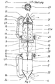
Figur 1 eine Viertakt-Brennkraftkolbenmaschine mit zwei gegenüberliegenden Zylindern und gleichlaufenden Kolben mit einem Kurbelschleifentrieb, mit einem Kolben im oberen Totpunkt, entsprechend Takt I,Figuren 2 bis 4 die Kolbenstellungen der beiden Zylinder nachFigur 1 gemäß den verschiedenen motorischen Takten II bis IV.
- 1 shows a four-stroke internal combustion piston engine with two opposing cylinders and synchronous pistons with a crank loop drive, with a piston at top dead center, corresponding to stroke I,
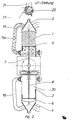
- Figures 2 to 4, the piston positions of the two cylinders of Figure 1 according to the different motor cycles II to IV.
Wie aus den Figuren 1 bis 4 hervorgeht, besteht die Viertakt-Brennkraftkolbenmaschine im wesentlichen aus zwei gegenüberliegenden Zylindern 1 und 2 mit aufgesetzten Zylinderköpfen 3 und 4. In den Zylindern 1 und 2 sind je ein Kolben 5 und 6 gelagert, die über geradlinig sich bewegende Kolbenstangen 7 und 8 und durch einen an diesen starr befestigten Kurbelschleifenrahmen 9 fest miteinander gekoppelt sind. Der Kurbelschleifenrahmen schließt eine Kulisse 10 ein, in der ein Gleitstein 11 läuft, der am Kurbelarm der Kurbelwelle 12 angreift. Am unteren Ende der Zylinder 1 und 2 sind an dort vorgesehenen überström-Rohrstutzen 13 und 14 Überströmkanäle 15 und 16 angeschlossen, die jeweils zu einem Zylinderkopfeinlaß 17 bzw. 18 führen. Die überströmkanäle 15 und 16 werden gesteuert durch überström-Rückschlagventile 19 und 20, die zu den überströmkanälen 15 und 16 hin öffnen, in umgekehrter Richtung jedoch sperren. Sowohl die Zylinderkopfeinlässe 17 und 18 als auch die Zylinderkopfauslässe 21 und 22 werden jeweils durch einen Drehschieber 23 bzw. 24 gesteuert. Ferner sind Ansaugstutzen 25 und 26 vorhanden, die ebenfalls am unteren Ende der Zylinder 1 und 2, und zwar gegenüber den überström-Rohrstutzen 13 und 14, angeordnet sind. Sie dienen zum Einströmen der Frischluft oder eines Kraftstoff-Luftgemisches. In diesen Ansaugstutzen 25 und 26 sind ebenfalls Einström-Rückschlagventile 27 und 28 eingebaut. Als Rückschlagventile dienen an sich bekannte Membran-Ventile.As can be seen from Figures 1 to 4, the four-stroke internal combustion engine consists essentially of two
Die dargestellte, nach dem Viertaktverfahren arbeitende Zweizylinder-Brennkraftkolbenmaschine arbeitet wie folgt: Nach Fig. 1 der Zeichnung hat der Kolben 5 gerade den Verdichtungstakt im Zylinder 1 beendet und befindet sich im oberen Totpunkt OT - Kurbelwelle und Drehschieber nehmen die Null-Stellung ein - . Während des Verdichtungstaktes hat der Kolben 5 gleichzeitig Frischluft (Ladeluft) oder ein Kraftstoff-Luftgemisch über den Ansaugstutzen 25 und das Einström-Rückschlagventil 27 in den unteren Zylinderraum 29 angesaugt. Der Drehschieber 23 verschließt während der vorbeschriebenen Vorgänge sowohl den Zylinderkopf-Einlaß 17 wie auch den Zylinderkopf-Auslaß 21 des Zylinderkopfes 3. Kurz bevor der Kolben 5 den oberen Totpunkt OT erreicht hat, setzt in üblicher Weise die Zündung ein und die Verbrennung des Kraftstoff-Luftgemisches beginnt. Durch den steigenden Druck der Verbrennungsgase wird der Kolben 5 zum unteren Totpunkt UT - die Kurbelwelle hat sich um 1800 und der Drehschieber um 90° gedreht - bewegt und schiebt dabei die im unteren Zylinderraum 29 befindliche Frischluft oder das Kraftstoff-Luftgemisch über das überström-Rückschlagventil 19 in den Überströmkanal 15 hinein. Diese Frischluftmenge bzw. Kraftstoff-Luftgemischmenge wird als erste Teilmenge (1.TM) der gesamten Frischluft bzw. des gesamten Kraftstoff-Luftgemisches zur vollen Aufladung eines Zylinders (eine Zylinderfüllung) bezeichnet (Fig. 1 und 2). Diese erste Teilmenge (1.TM) an Frischluft bzw. an Kraftstoff-Luftgemisch bleibt während des darauffolgenden Auspufftaktes, bei dem der Kolben 5 sich zum oberen Totpunkt OT - Kurbelwellendrehung 360°, Drehschieberdrehung 180° - hin bewegt, im Überströmkanal 15 vorverdichtet gespeichert; vgl. Fig. 3. Um einen Vordruck dieser ersten Teilmenge zu erreichen, ist der Überströmkanal 15 (auch der überströmkanal 16) volumenmäßig kleiner als das Hubvolumen des unteren Zylinderraumes 29, des Zylinders 1 und des unteren Zylinderraumes 30 des Zylinders 2. Während des Auspufftaktes wird eine zweite Teilmenge (2.TM) von Frischluft bzw. Ladeluft oder Kraftstoff-Luftgemisch durch den Ansaugstutzen 25 über das Einström-Rückschlagventil 27 in den unteren Zylinderraum 29 hinein durch Unterdruck gefördert (Fig. 3).The two-cylinder internal combustion engine which works according to the four-stroke process works as follows: According to FIG. 1 of the drawing, the
Nun erfolgt der Ansaugtakt (Fig. 4), bei dem der Kolben 5 nach unten in den UT geht - Kurbelwellendrehung nunmehr 540°, Drehschieberdrehung nunmehr 270° - und der Zylinderkopfeinlaß 17 durch den Drehschieber 23 freigegeben ist. Die im überströmkanal 15 mit Überdruck gespeicherte erste Teilmenge (1.TM) der Ladeluft oder des Kraftstoff-Luftgemisches strömt sofort mit hoher Eigendynamik in den Verbrennungsraum 30 ein; ihr folgt die durch den abwärts sich bewegenden Kolben 5 angetriebene zweite Teilmenge (2.TM) der Ladeluft oder des Kraftstoff-Luftgemisches über das Überström-Rückschlagventil 19 und durch den Überströmkanal 15 sofort nach (Fig. 4) - Kurbelwellendrehung nunmehr 720° (wieder bei 0°), Drehschieberdrehung nunmehr 360° (wieder bei 0°) - .Now the intake stroke (Fig. 4) takes place, in which the
Der Zylinder 2 arbeitet zusammen mit seinem Kolben 6 in bezug auf den Zylinder 1 mit seinem Kolben 5 um 180° phasenverschoben, wie sich aus der Zeichnung in Verbindung mit der vorstehenden Beschreibung sofort ergibt.The
Claims (5)
Applications Claiming Priority (2)
| Application Number | Priority Date | Filing Date | Title |
|---|---|---|---|
| DE3507108 | 1985-02-28 | ||
| DE19853507108 DE3507108A1 (en) | 1985-02-28 | 1985-02-28 | FOUR-STROKE COMBUSTION PISTON |
Publications (1)
| Publication Number | Publication Date |
|---|---|
| EP0193183A1 true EP0193183A1 (en) | 1986-09-03 |
Family
ID=6263809
Family Applications (1)
| Application Number | Title | Priority Date | Filing Date |
|---|---|---|---|
| EP86102487A Withdrawn EP0193183A1 (en) | 1985-02-28 | 1986-02-26 | Four-shoke internal-combustion engine |
Country Status (4)
| Country | Link |
|---|---|
| US (1) | US4715336A (en) |
| EP (1) | EP0193183A1 (en) |
| JP (1) | JPS61205328A (en) |
| DE (1) | DE3507108A1 (en) |
Cited By (2)
| Publication number | Priority date | Publication date | Assignee | Title |
|---|---|---|---|---|
| DE4220200A1 (en) * | 1991-06-20 | 1993-01-21 | Mitsubishi Heavy Ind Ltd | FOUR-STOCK COMBUSTION ENGINE |
| FR2710949A1 (en) * | 1993-10-06 | 1995-04-14 | Baltus Elie | Engine or pump, the piston of which is rigidly connected to a frame equipped with an opening accommodating a crankshaft crank wrist |
Families Citing this family (12)
| Publication number | Priority date | Publication date | Assignee | Title |
|---|---|---|---|---|
| US4838214A (en) * | 1987-06-18 | 1989-06-13 | Barrett George M | Internal combustion engine assembly |
| FR2624910A1 (en) * | 1987-12-16 | 1989-06-23 | Pradom Ltd | DISTRIBUTION METHOD AND DEVICE FOR VOLUMETRIC ENGINE AND COMPRESSOR |
| DE4007466A1 (en) * | 1990-03-09 | 1991-02-14 | Franz Josef Knott | Reduced emissions two=stroke IC engine - has separately lubricated piston which operates without oil being mixed with fuel |
| DE4011140C2 (en) * | 1990-04-06 | 1999-12-02 | Werner Bohne | Two-stroke internal combustion engine with mixture-free purging, adjustable inlet and outlet device, as well as lift shaft-free power transmission, in a two-cylinder design |
| DE19523114A1 (en) * | 1995-06-26 | 1997-01-02 | Sandor Nagy | IC engine with reciprocating piston |
| GB9719548D0 (en) | 1997-09-15 | 1997-11-19 | Stone Timothy | Improvements in and relating to internal combustion engines |
| US20080289488A1 (en) | 1999-04-01 | 2008-11-27 | Peter Robert Raffaele | Reciprocating fluid machines |
| US6189493B1 (en) * | 1999-07-13 | 2001-02-20 | The United States Of America As Represented By The Administrator Of The United States Environmental Protection Agency | Torque balanced opposed-piston engine |
| AUPR459501A0 (en) * | 2001-04-27 | 2001-05-24 | Raffaele, Michael John | Improvements in engines and components |
| WO2012148365A1 (en) * | 2011-04-27 | 2012-11-01 | TOPRAK, Ahmet | Easy-to-produce, high efficiency internal combustion engine |
| US10012145B1 (en) * | 2017-12-01 | 2018-07-03 | Alberto Francisco Araujo | Internal combustion engine with coaxially aligned pistons |
| US10378578B1 (en) | 2018-07-13 | 2019-08-13 | Alberto Francisco Araujo | Internal combustion engine using yoke assemblies in unopposed cylinder units |
Citations (5)
| Publication number | Priority date | Publication date | Assignee | Title |
|---|---|---|---|---|
| US2405016A (en) * | 1943-07-21 | 1946-07-30 | William H Cook | Piston and cylinder device |
| FR1434275A (en) * | 1965-02-22 | 1966-04-08 | Movement transformation mechanism, adaptable to piston machines | |
| DE1751219A1 (en) * | 1968-04-23 | 1971-05-27 | Aspin Frank Metcalfe | Rotary valve for internal combustion engines |
| AU3687978A (en) * | 1978-06-06 | 1979-12-13 | Norman George Wheatley | Opposed piston internal combustion engine |
| DE3022901A1 (en) * | 1980-06-19 | 1981-12-24 | Helmut 8000 München Pohl | Four stroke IC engine - has crankcase connected via non-return valve to fuel mixture supply and to precompression chamber |
Family Cites Families (7)
| Publication number | Priority date | Publication date | Assignee | Title |
|---|---|---|---|---|
| DE1140406B (en) * | 1956-06-06 | 1962-11-29 | F M Aspin Engines Ltd | Hollow rotary valve with a conical base |
| US3517652A (en) * | 1968-05-10 | 1970-06-30 | Johnson Engine Works Co The | Two-cycle engine |
| SE395301B (en) * | 1971-11-15 | 1977-08-08 | Motoren Forschungs Kg Franke M | FRONT POWER COMBUSTION ENGINE |
| DE2756308A1 (en) * | 1977-12-17 | 1979-06-21 | Motoren Forschungs Gmbh | Four-stroke reciprocating IC engine - has auxiliary compression chamber for mixt. on underside of piston |
| JPS54158513A (en) * | 1978-06-02 | 1979-12-14 | Dana Corp | Fourrcycle internal combustion engine |
| US4311119A (en) * | 1979-04-05 | 1982-01-19 | Menzies Murray A | Internal combustion engines |
| JPS5844251A (en) * | 1981-09-08 | 1983-03-15 | Mitsubishi Electric Corp | Mixture feeder for internal-combustion engine |
-
1985
- 1985-02-28 DE DE19853507108 patent/DE3507108A1/en not_active Withdrawn
-
1986
- 1986-02-26 US US06/833,814 patent/US4715336A/en not_active Expired - Fee Related
- 1986-02-26 EP EP86102487A patent/EP0193183A1/en not_active Withdrawn
- 1986-02-28 JP JP61043930A patent/JPS61205328A/en active Pending
Patent Citations (5)
| Publication number | Priority date | Publication date | Assignee | Title |
|---|---|---|---|---|
| US2405016A (en) * | 1943-07-21 | 1946-07-30 | William H Cook | Piston and cylinder device |
| FR1434275A (en) * | 1965-02-22 | 1966-04-08 | Movement transformation mechanism, adaptable to piston machines | |
| DE1751219A1 (en) * | 1968-04-23 | 1971-05-27 | Aspin Frank Metcalfe | Rotary valve for internal combustion engines |
| AU3687978A (en) * | 1978-06-06 | 1979-12-13 | Norman George Wheatley | Opposed piston internal combustion engine |
| DE3022901A1 (en) * | 1980-06-19 | 1981-12-24 | Helmut 8000 München Pohl | Four stroke IC engine - has crankcase connected via non-return valve to fuel mixture supply and to precompression chamber |
Cited By (4)
| Publication number | Priority date | Publication date | Assignee | Title |
|---|---|---|---|---|
| DE4220200A1 (en) * | 1991-06-20 | 1993-01-21 | Mitsubishi Heavy Ind Ltd | FOUR-STOCK COMBUSTION ENGINE |
| AU644965B2 (en) * | 1991-06-20 | 1993-12-23 | Mitsubishi Jukogyo Kabushiki Kaisha | 4-cycle engine |
| DE4220200C2 (en) * | 1991-06-20 | 2000-09-21 | Mitsubishi Heavy Ind Ltd | Four stroke internal combustion engine |
| FR2710949A1 (en) * | 1993-10-06 | 1995-04-14 | Baltus Elie | Engine or pump, the piston of which is rigidly connected to a frame equipped with an opening accommodating a crankshaft crank wrist |
Also Published As
| Publication number | Publication date |
|---|---|
| US4715336A (en) | 1987-12-29 |
| JPS61205328A (en) | 1986-09-11 |
| DE3507108A1 (en) | 1986-08-28 |
Similar Documents
| Publication | Publication Date | Title |
|---|---|---|
| EP0379720B1 (en) | Method for increasing the brake power of a four-stroke alternating piston-type internal-combustion engine | |
| DE10311358B4 (en) | Reciprocating internal combustion engine, method for their operation and apparatus for adjusting the lifting function of a charge exchange valve | |
| DE60018609T2 (en) | Piston engine with balancing and charging | |
| EP0193183A1 (en) | Four-shoke internal-combustion engine | |
| DE2844308C2 (en) | Two-stroke internal combustion engine | |
| DE3712750A1 (en) | Two-stroke internal combustion engine, especially of reciprocating piston type | |
| DE3134791A1 (en) | Internal combustion engine | |
| EP0126464B1 (en) | Method of supplying combustion air to the combustion chamber of an internal-combustion engine | |
| DE3137454A1 (en) | Internal combustion engine, especially for motor vehicles, with the exhaust gas pressure used to improve the cylinder charging | |
| DE3137471C2 (en) | ||
| DE3024812A1 (en) | Suction system for four-stroke IC engine - has non-return valve positioned to reduce reverse flow pressure shock | |
| DE3137490A1 (en) | Reciprocating piston internal combustion engine, especially for motor vehicles, with a charging device | |
| DE19800137C2 (en) | Intake and exhaust systems for connecting rodless double-piston internal combustion engines in two and four stroke versions | |
| DE4311620A1 (en) | Two-stroke engine | |
| DE3842802A1 (en) | Double-piston assembly, especially internal combustion engine | |
| DE1003986B (en) | Four-stroke internal combustion engine | |
| DE3837502A1 (en) | Two-stroke engine with scavenging and supercharging | |
| DE4036537C1 (en) | IC engine toxics reduction system - involves mixing off-gas from previous cycle to fresh air content | |
| DE2741649A1 (en) | Four stroke combustion engine - has mixt. inlet into crank case connected via synchronously actuated valve to engine inlet valve | |
| DE529910C (en) | Multi-cylinder two-stroke internal combustion engine with stepped piston pumps | |
| DE181206C (en) | ||
| DE2156586C3 (en) | Four-stroke internal combustion engine with Uberströmkanalsyslem | |
| DE934134C (en) | Preferably slot-controlled two-stroke internal combustion engine, especially for motor vehicles | |
| DE612584C (en) | Multi-cylinder two-stroke internal combustion engine with charge pumps | |
| DE102011009277B4 (en) | Internal combustion engine with labor. and auxiliary cylinders |
Legal Events
| Date | Code | Title | Description |
|---|---|---|---|
| PUAI | Public reference made under article 153(3) epc to a published international application that has entered the european phase |
Free format text: ORIGINAL CODE: 0009012 |
|
| AK | Designated contracting states |
Kind code of ref document: A1 Designated state(s): AT DE FR GB IT SE |
|
| 17P | Request for examination filed |
Effective date: 19870109 |
|
| 17Q | First examination report despatched |
Effective date: 19870624 |
|
| STAA | Information on the status of an ep patent application or granted ep patent |
Free format text: STATUS: THE APPLICATION IS DEEMED TO BE WITHDRAWN |
|
| 18D | Application deemed to be withdrawn |
Effective date: 19871103 |
|
| RIN1 | Information on inventor provided before grant (corrected) |
Inventor name: SCHINDLER, MANFRED Inventor name: FICHT, REINHOLD |