EP0192980B1 - Leichter Tauchkolben für Verbrennungsmotoren - Google Patents
Leichter Tauchkolben für Verbrennungsmotoren Download PDFInfo
- Publication number
- EP0192980B1 EP0192980B1 EP86101114A EP86101114A EP0192980B1 EP 0192980 B1 EP0192980 B1 EP 0192980B1 EP 86101114 A EP86101114 A EP 86101114A EP 86101114 A EP86101114 A EP 86101114A EP 0192980 B1 EP0192980 B1 EP 0192980B1
- Authority
- EP
- European Patent Office
- Prior art keywords
- piston
- gudgeon pin
- guide plate
- connecting rod
- degrees
- Prior art date
- Legal status (The legal status is an assumption and is not a legal conclusion. Google has not performed a legal analysis and makes no representation as to the accuracy of the status listed.)
- Expired
Links
Images
Classifications
-
- F—MECHANICAL ENGINEERING; LIGHTING; HEATING; WEAPONS; BLASTING
- F16—ENGINEERING ELEMENTS AND UNITS; GENERAL MEASURES FOR PRODUCING AND MAINTAINING EFFECTIVE FUNCTIONING OF MACHINES OR INSTALLATIONS; THERMAL INSULATION IN GENERAL
- F16J—PISTONS; CYLINDERS; SEALINGS
- F16J1/00—Pistons; Trunk pistons; Plungers
- F16J1/02—Bearing surfaces
Definitions
- the invention relates to a lightweight plunger for internal combustion engines according to the preamble of claim 1.
- Such a piston is known from EP 0 050 256 A1.
- Expedient embodiments of the invention contain the subclaims. Due to the lateral edge retraction on the shaft guide plates according to claim 2, a hard tarnishing of the lateral guide plate edges against the cylinder running surface is avoided.
- Claim 4 is achieved by the metal strip a control effect in the guide plate in question.
- This control effect has the effect that the lower end of the guide plate in question is drawn in radially inwards as the temperature rises.
- the piston is made of aluminum and consists essentially of the head part 1 with a ring section and the guide plates 2, 3 in the shaft area and the pin bosses 4 freely suspended on the piston head Connection.
- the ribs 5 are arranged at an angle of 45 ° to the pin axis with an apex in the piston axis.
- the ribs 5 thus lie on the 45 ° diagonal plane between the pin and connecting rod oscillation plane.
- the arrangement of the ribs 5 at such an angle ensures excellent running results in the piston according to the invention.
- the guide plates 2 are symmetrical in terms of area to the 45 ° diagonal plane and thus likewise to the ribs 5. At their upper end, the guide plates 2 each span an angle of approximately 40 ° .
- the guide plates 2 taper downwards on their two long sides at an angle of 10 ° . Such a surface tapering downwards proves to be particularly favorable in terms of weight saving and running behavior of the piston.
- the guide plates 2 are arranged at a distance below the lowest ring web of the ring section.
- guide plates 2 are preferably arranged on the pressure side of the piston, only a guide plate 3 molded directly onto the piston head is provided on the counterpressure side of the piston.
- the width of the guide plate 3 in the circumferential direction also tapers in a manner similar to that of the guide plates 2 towards the lower end of the piston. At the upper end, this guide plate extends over an angle of 50 °, which decreases to 40 ° to the lower end.
- a metal strip 6 is formed in the interior of the guide plate 3 in the longitudinal direction of the piston and extends in the piston head part 1 to the underside of the piston head.
- the metal strip 6, if it is made of a material whose thermal expansion coefficient is smaller than that of aluminum, has a regulating effect in the guide plate 3 in that the lower end of the guide plate 3 retracts radially inward with increasing temperature.
Description
- Die Erfindung betrifft einen leichten Tauchkolben für Verbrennungsmotoren nach dem Oberbegriff des Anspruchs 1.
- Ein solcher Kolben ist aus der EP 0 050 256 A1 bekannt.
- Es ist Aufgabe der vorliegenden Erfindung, die im Schaftbereich jenes bekannten Kolbens bereits vorhandene Flexibilität bei Aufrechterhaltung einer guten Seitenführung des Kolbens in Richtung der Kolbenbolzenachse noch weiter zu erhöhen.
- Gelöst wird diese Aufgabe durch eine Ausbildung des Kolbenschaftes nach den kennzeichnenden Merkmalen des Anspruchs 1.
- Zweckmäßige Ausgestaltungen der Erfindung enthalten die Unteransprüche. Durch den seitlichen Randeinzug an den Schaft-Führungsplatten nach Anspruch 2 wird ein hartes Anlaufen der seitlichen Führungsplattenränder an die Zylinderlauffläche vermieden.
- Die auf einer der Tragseiten des Schaftes mittig zwischen den Bolzennaben an die Ringpartie des Kolbenkopfes angeformte einzelne Führungsplatte wird durch den im Inneren an sie angeformten Metallstreifen nach Anspruch 3 versteift.
- Bei Verwendung eines Metallstreifens aus einem Material mit geringerer Wärmeausdehnung als derjenigen des Kolbengrundmaterials gem. Anspruch 4 wird durch den Metallstreifen ein Regeleffekt bei der betreffenden Führungsplatte erreicht. Dieser Regeleffekt wirkt dahingehend, daß das untere Ende der betreffenden Führungsplatte bei steigender Temperatur radial nach innen eingezogen wird.
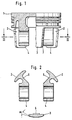
- Ein Ausführungsbeispiel der Erfindung ist in der Zeichnung dargestellt. Und zwar zeigen:
- Fig. 1 einen Kolben zum Teil im Schnitt (linker Teil) und zum Teil in der Ansicht (rechter Teil),
- Fig. 2 einen Schnitt durch den Kolben nach Linie 11-11
- Der Kolben ist aus Aluminium und besteht im wesentlichen aus dem Kopfteil 1 mit Ringpartie und den Führungsplatten 2, 3 im Schaftbereich sowie den am Kolbenboden frei angehängten Bolzennaben 4. Mit dem Kolbenoberteil stehen die Führungsplatten 2 lediglich über die von den Bolzennaben 4 ausgehenden Rippen 5 in Verbindung. Die Rippen 5 sind zur Bolzenachse in einem Winkel von 45° mit Scheitelpunkt in der Kolbenachse angeordnet. Damit liegen die Rippen 5 auf der 45° Diagonalebene zwischen Bolzen- und Pleuelschwingebene. Die Anordung der Rippen 5 unter einem solchen Winkel sorgt beim erfindungsgemäßen Kolben für ausgezeichnete Laufergebnisse. Die Führungsplatten 2 sind in Umfangsrichtung flächenmäßig symmetrisch zu der 45° Diagonalebene und damit gleichfalls zu den Rippen 5. An ihrem oberen Ende überspannen die Führungsplatten 2 je einen Winkel von etwa 40°. Nach unten verjüngen sich die Führungsplatten 2 und zwar auf ihren beiden Längsseiten jeweils unter einem Winkel von 10°. Eine derart sich nach unten verjüngende Flächenausbildung erweist sich in bezug auf Gewichtseinsparung und Laufverhalten des Kolbens als besonders günstig. Die Führungsplatten 2 sind mit Abstand unterhalb des untersten Ringsteges der Ringpartie angeordnet.
- Während die Führungsplatten 2 bevorzugt auf der Druckseite des Kolbens angeordnet sind, ist an der Gegendruckseite des Kolbens lediglich eine direkt an den Kolbenkopf angeformte Führungsplatte 3 vorgesehen. Die Breite der Führungsplatte 3 in Umfangsrichtung verjüngt sich ebenfalls ähnlich wie bei den Führungsplatten 2 zum unteren Ende des Kolbens hin. Am oberen Ende erstreckt sich diese Führungsplatte über einen Winkel von 50°, der zum unteren Ende auf 40° abnimmt.
- In Kolbenlängsrichtung ist im Inneren der Führungsplatte 3 ein Metallstreifen 6 eingeformt, der im Kolbenkopfteil 1 bis an die Unterseite des Kolbenbo-dens reicht. Der Metallstreifen 6 bewirkt, wenn er aus einem Material ist, dessen Wärmeausdehnungskoeffizient gegenüber demjenigen von Aluminium kleiner ist, einen Regeleffekt bei der Führungsplatte 3 dahingehend, daß sich das untere Ende der Führungsplatte 3 mit steigender Temperatur radial nach innen einzieht.
- Die schraffierten Seitenbereiche 7 der Führungsplatte sind unter einem Winkel von a = 4° radial nach innen eingezogen und zwar derart, daß die Seitenkante der Führungsfläche aus dessen Hauptlauffläche um 100 gm zurückgesetzt ist.
Claims (4)
Applications Claiming Priority (2)
| Application Number | Priority Date | Filing Date | Title |
|---|---|---|---|
| DE3505037 | 1985-02-14 | ||
| DE19853505037 DE3505037A1 (de) | 1985-02-14 | 1985-02-14 | Leichter tauchkolben fuer verbrennungsmotoren |
Publications (3)
| Publication Number | Publication Date |
|---|---|
| EP0192980A2 EP0192980A2 (de) | 1986-09-03 |
| EP0192980A3 EP0192980A3 (en) | 1987-10-07 |
| EP0192980B1 true EP0192980B1 (de) | 1989-06-14 |
Family
ID=6262491
Family Applications (1)
| Application Number | Title | Priority Date | Filing Date |
|---|---|---|---|
| EP86101114A Expired EP0192980B1 (de) | 1985-02-14 | 1986-01-28 | Leichter Tauchkolben für Verbrennungsmotoren |
Country Status (4)
| Country | Link |
|---|---|
| US (1) | US4638725A (de) |
| EP (1) | EP0192980B1 (de) |
| JP (1) | JPS61190151A (de) |
| DE (2) | DE3505037A1 (de) |
Families Citing this family (4)
| Publication number | Priority date | Publication date | Assignee | Title |
|---|---|---|---|---|
| DE19547157A1 (de) * | 1995-12-16 | 1997-06-19 | Mahle Gmbh | Kolben-Zylinder-Baueinheit |
| JP3964534B2 (ja) * | 1998-03-27 | 2007-08-22 | サンデン株式会社 | ピストン |
| CN104405517B (zh) * | 2014-11-19 | 2017-01-04 | 山东滨州渤海活塞股份有限公司 | 用于汽油机的轻量化降噪音活塞 |
| EP3246555B1 (de) * | 2016-05-17 | 2020-07-08 | Nicolas Perret | Kolben für verbrennungsmotor, der eine leichtere struktur besitzt |
Family Cites Families (4)
| Publication number | Priority date | Publication date | Assignee | Title |
|---|---|---|---|---|
| US1498689A (en) * | 1920-06-16 | 1924-06-24 | Jacob R Francis | Spring piston |
| FR1081089A (fr) * | 1953-07-10 | 1954-12-15 | Renault | Piston en particulier pour moteurs à explosions |
| AU503148B2 (en) * | 1975-06-16 | 1979-08-23 | Cummins Engine Company, Inc | Piston with flexible heat dam |
| DE3039382A1 (de) * | 1980-10-18 | 1982-04-22 | Mahle Gmbh, 7000 Stuttgart | Leichter tachkolben fuer verbrennungsmotoren |
-
1985
- 1985-02-14 DE DE19853505037 patent/DE3505037A1/de not_active Ceased
-
1986
- 1986-01-28 EP EP86101114A patent/EP0192980B1/de not_active Expired
- 1986-01-28 DE DE8686101114T patent/DE3663987D1/de not_active Expired
- 1986-02-13 JP JP61028086A patent/JPS61190151A/ja active Pending
- 1986-02-13 US US06/828,789 patent/US4638725A/en not_active Expired - Fee Related
Also Published As
| Publication number | Publication date |
|---|---|
| JPS61190151A (ja) | 1986-08-23 |
| EP0192980A2 (de) | 1986-09-03 |
| DE3505037A1 (de) | 1986-08-14 |
| US4638725A (en) | 1987-01-27 |
| EP0192980A3 (en) | 1987-10-07 |
| DE3663987D1 (en) | 1989-07-20 |
Similar Documents
| Publication | Publication Date | Title |
|---|---|---|
| DE2625191C2 (de) | Einstückiger Kolben für Brennkraftmaschinen | |
| DE60301636T2 (de) | Kolben | |
| EP0356457B1 (de) | Leichtmetall-tauchkolben für verbrennungsmotoren | |
| DE3425965A1 (de) | Leichtmetallkolben fuer brennkraftmaschinen | |
| DE3229320A1 (de) | Zylinderkopfdichtung | |
| EP3004609A1 (de) | Kolben für einen verbrennungsmotor | |
| DE4007992C2 (de) | ||
| EP0449848B1 (de) | Leichter tauchkolben für verbrennungsmotoren | |
| EP0192980B1 (de) | Leichter Tauchkolben für Verbrennungsmotoren | |
| EP0359932B1 (de) | Ölgekühlter Kolben für Verbrennungsmotoren | |
| WO1989002982A1 (en) | Cooled plunger for internal combustion engines | |
| EP0050256B1 (de) | Leichter Tauchkolben für Verbrennungsmotoren | |
| DE2938175C2 (de) | Kolben für Brennkraftmaschinen mit Brennraummulde im Kolbenboden | |
| DE3523438C2 (de) | ||
| DE3707462C2 (de) | ||
| DE2407788A1 (de) | Hubkolben | |
| DE3843761A1 (de) | Leichter tauchkolben fuer verbrennungsmotoren | |
| DE7602960U1 (de) | Kolben fuer verbrennungskraftmaschinen | |
| DE924297C (de) | Kolben fuer Brennkraftmaschinen, insbesondere fuer Zweitaktmaschinen | |
| DD243530A1 (de) | Eisenkolben fuer hubkolbenbrennkraftmaschinen | |
| DE4338571A1 (de) | Kolben für einen Verbrennungsmotor | |
| DE19953384C1 (de) | Kolben | |
| DE3838217A1 (de) | Tauchkolben fuer verbrennungsmotoren | |
| DE3723005C2 (de) | Tauchkolben für Verbrennungsmotoren | |
| DE3428490A1 (de) | Tauchkolben fuer verbrennungsmotoren |
Legal Events
| Date | Code | Title | Description |
|---|---|---|---|
| PUAI | Public reference made under article 153(3) epc to a published international application that has entered the european phase |
Free format text: ORIGINAL CODE: 0009012 |
|
| AK | Designated contracting states |
Kind code of ref document: A2 Designated state(s): DE FR GB IT |
|
| PUAL | Search report despatched |
Free format text: ORIGINAL CODE: 0009013 |
|
| AK | Designated contracting states |
Kind code of ref document: A3 Designated state(s): DE FR GB IT |
|
| 17P | Request for examination filed |
Effective date: 19880302 |
|
| 17Q | First examination report despatched |
Effective date: 19881012 |
|
| GRAA | (expected) grant |
Free format text: ORIGINAL CODE: 0009210 |
|
| AK | Designated contracting states |
Kind code of ref document: B1 Designated state(s): DE FR GB IT |
|
| ITF | It: translation for a ep patent filed |
Owner name: DE DOMINICIS & MAYER S.R.L. |
|
| GBT | Gb: translation of ep patent filed (gb section 77(6)(a)/1977) | ||
| REF | Corresponds to: |
Ref document number: 3663987 Country of ref document: DE Date of ref document: 19890720 |
|
| ET | Fr: translation filed | ||
| PLBE | No opposition filed within time limit |
Free format text: ORIGINAL CODE: 0009261 |
|
| STAA | Information on the status of an ep patent application or granted ep patent |
Free format text: STATUS: NO OPPOSITION FILED WITHIN TIME LIMIT |
|
| 26N | No opposition filed | ||
| ITTA | It: last paid annual fee | ||
| PGFP | Annual fee paid to national office [announced via postgrant information from national office to epo] |
Ref country code: GB Payment date: 19911224 Year of fee payment: 7 |
|
| PGFP | Annual fee paid to national office [announced via postgrant information from national office to epo] |
Ref country code: FR Payment date: 19920110 Year of fee payment: 7 |
|
| PG25 | Lapsed in a contracting state [announced via postgrant information from national office to epo] |
Ref country code: GB Effective date: 19930128 |
|
| GBPC | Gb: european patent ceased through non-payment of renewal fee |
Effective date: 19930128 |
|
| PG25 | Lapsed in a contracting state [announced via postgrant information from national office to epo] |
Ref country code: FR Effective date: 19930930 |
|
| REG | Reference to a national code |
Ref country code: FR Ref legal event code: ST |
|
| PGFP | Annual fee paid to national office [announced via postgrant information from national office to epo] |
Ref country code: DE Payment date: 20020212 Year of fee payment: 17 |
|
| PG25 | Lapsed in a contracting state [announced via postgrant information from national office to epo] |
Ref country code: DE Free format text: LAPSE BECAUSE OF NON-PAYMENT OF DUE FEES Effective date: 20030801 |
|
| PG25 | Lapsed in a contracting state [announced via postgrant information from national office to epo] |
Ref country code: IT Free format text: LAPSE BECAUSE OF NON-PAYMENT OF DUE FEES;WARNING: LAPSES OF ITALIAN PATENTS WITH EFFECTIVE DATE BEFORE 2007 MAY HAVE OCCURRED AT ANY TIME BEFORE 2007. THE CORRECT EFFECTIVE DATE MAY BE DIFFERENT FROM THE ONE RECORDED. Effective date: 20050128 |