EP0192073A1 - Druckreduzierungsanordnung für eine Vorrichtung zum pneumatischen Fördern von körnigen Gütern - Google Patents
Druckreduzierungsanordnung für eine Vorrichtung zum pneumatischen Fördern von körnigen Gütern Download PDFInfo
- Publication number
- EP0192073A1 EP0192073A1 EP86100806A EP86100806A EP0192073A1 EP 0192073 A1 EP0192073 A1 EP 0192073A1 EP 86100806 A EP86100806 A EP 86100806A EP 86100806 A EP86100806 A EP 86100806A EP 0192073 A1 EP0192073 A1 EP 0192073A1
- Authority
- EP
- European Patent Office
- Prior art keywords
- pressure reducing
- reducing device
- transport
- nozzle
- transport channel
- Prior art date
- Legal status (The legal status is an assumption and is not a legal conclusion. Google has not performed a legal analysis and makes no representation as to the accuracy of the status listed.)
- Granted
Links
- 230000001603 reducing effect Effects 0.000 title claims abstract description 75
- 239000011236 particulate material Substances 0.000 title claims abstract description 11
- 239000000428 dust Substances 0.000 claims abstract description 51
- 239000000463 material Substances 0.000 claims abstract description 15
- 208000016791 bilateral striopallidodentate calcinosis Diseases 0.000 claims abstract description 9
- 239000007787 solid Substances 0.000 claims abstract description 5
- 239000012535 impurity Substances 0.000 claims abstract description 3
- 230000007704 transition Effects 0.000 claims abstract 2
- 239000007789 gas Substances 0.000 claims description 35
- VNWKTOKETHGBQD-UHFFFAOYSA-N methane Chemical compound C VNWKTOKETHGBQD-UHFFFAOYSA-N 0.000 claims description 6
- 238000011144 upstream manufacturing Methods 0.000 claims description 6
- 239000003345 natural gas Substances 0.000 claims description 3
- 239000004576 sand Substances 0.000 claims 2
- 239000002245 particle Substances 0.000 description 14
- 238000001816 cooling Methods 0.000 description 9
- 238000002485 combustion reaction Methods 0.000 description 8
- 230000003628 erosive effect Effects 0.000 description 5
- JTJMJGYZQZDUJJ-UHFFFAOYSA-N phencyclidine Chemical class C1CCCCN1C1(C=2C=CC=CC=2)CCCCC1 JTJMJGYZQZDUJJ-UHFFFAOYSA-N 0.000 description 5
- 238000005452 bending Methods 0.000 description 3
- 238000005422 blasting Methods 0.000 description 3
- 239000000567 combustion gas Substances 0.000 description 3
- 238000004519 manufacturing process Methods 0.000 description 3
- 230000002829 reductive effect Effects 0.000 description 3
- 238000004140 cleaning Methods 0.000 description 2
- 230000000694 effects Effects 0.000 description 2
- 230000002093 peripheral effect Effects 0.000 description 2
- 235000002918 Fraxinus excelsior Nutrition 0.000 description 1
- 230000001133 acceleration Effects 0.000 description 1
- 239000002956 ash Substances 0.000 description 1
- 230000005540 biological transmission Effects 0.000 description 1
- 229910010293 ceramic material Inorganic materials 0.000 description 1
- 239000003245 coal Substances 0.000 description 1
- 239000011248 coating agent Substances 0.000 description 1
- 238000000576 coating method Methods 0.000 description 1
- 238000010276 construction Methods 0.000 description 1
- 230000003247 decreasing effect Effects 0.000 description 1
- 230000001419 dependent effect Effects 0.000 description 1
- 238000011161 development Methods 0.000 description 1
- 230000018109 developmental process Effects 0.000 description 1
- 230000002349 favourable effect Effects 0.000 description 1
- 238000005243 fluidization Methods 0.000 description 1
- 239000000446 fuel Substances 0.000 description 1
- 239000008187 granular material Substances 0.000 description 1
- 239000002184 metal Substances 0.000 description 1
- 150000001247 metal acetylides Chemical class 0.000 description 1
- 229910001092 metal group alloy Inorganic materials 0.000 description 1
- 230000036961 partial effect Effects 0.000 description 1
- 230000000284 resting effect Effects 0.000 description 1
- 238000005488 sandblasting Methods 0.000 description 1
- 238000000926 separation method Methods 0.000 description 1
- 239000011343 solid material Substances 0.000 description 1
Images


Classifications
-
- F—MECHANICAL ENGINEERING; LIGHTING; HEATING; WEAPONS; BLASTING
- F23—COMBUSTION APPARATUS; COMBUSTION PROCESSES
- F23C—METHODS OR APPARATUS FOR COMBUSTION USING FLUID FUEL OR SOLID FUEL SUSPENDED IN A CARRIER GAS OR AIR
- F23C10/00—Fluidised bed combustion apparatus
- F23C10/16—Fluidised bed combustion apparatus specially adapted for operation at superatmospheric pressures, e.g. by the arrangement of the combustion chamber and its auxiliary systems inside a pressure vessel
-
- B—PERFORMING OPERATIONS; TRANSPORTING
- B65—CONVEYING; PACKING; STORING; HANDLING THIN OR FILAMENTARY MATERIAL
- B65G—TRANSPORT OR STORAGE DEVICES, e.g. CONVEYORS FOR LOADING OR TIPPING, SHOP CONVEYOR SYSTEMS OR PNEUMATIC TUBE CONVEYORS
- B65G53/00—Conveying materials in bulk through troughs, pipes or tubes by floating the materials or by flow of gas, liquid or foam
- B65G53/34—Details
- B65G53/40—Feeding or discharging devices
- B65G53/42—Nozzles
-
- C—CHEMISTRY; METALLURGY
- C21—METALLURGY OF IRON
- C21B—MANUFACTURE OF IRON OR STEEL
- C21B5/00—Making pig-iron in the blast furnace
- C21B5/001—Injecting additional fuel or reducing agents
- C21B5/003—Injection of pulverulent coal
-
- F—MECHANICAL ENGINEERING; LIGHTING; HEATING; WEAPONS; BLASTING
- F23—COMBUSTION APPARATUS; COMBUSTION PROCESSES
- F23J—REMOVAL OR TREATMENT OF COMBUSTION PRODUCTS OR COMBUSTION RESIDUES; FLUES
- F23J3/00—Removing solid residues from passages or chambers beyond the fire, e.g. from flues by soot blowers
- F23J3/06—Systems for accumulating residues from different parts of furnace plant
Definitions
- the invention relates to a pressure reducing device according to the precharacterising part of claim 1.
- This pressure reducing device is particularly intended for transport devices for the transmission of particulate material from a first container, which is under a high pressure, to a second container, which is under a lower pressure, as for example a transport device for continuous removal of dust from a dust separator for cleaning of combustion gases in a PFBC plant to a collecting container for separated dust located outside the pressure vessel that encapsulates the fluidized bed combustor and the cleaning equipment of the plant. It can also be used for other purposes, for example as a unit (nozzle) in a sand blasting plant.
- a pneumatic transport device for conveying a particulate material from a first container, which is under high pressure, to a second container, which is under lower pressure is described in detail in EP-A-83306073.4 (01 08 505).
- This document shows the transport device applied to a PFBC plant for the removal of separated dust from series-connected dust separators, for example cyclones, in a pressure vessel to a container outside the pressure vessel.
- the transport device also comprises a tube system in which the gas/dust flow is bent repeatedly in order to successively reduce the pressure to atmospheric level. The pressure reduction is performed in a large number of stages.
- the transport device is made in the form of a cooler and placed in the pressufe vessel so that it is cooled by the combustion air thereby preheating the latter to recover part of the thermal energy from the transport gas and the dust.
- the pressure in the pressure vessel may amount to 1.0-2 MPa (10-20 bar).
- the pressure varies with the load, usually between about 0.3 and 1.5 MPa (3-15 bar).
- the pressure drops somewhat, thus obtaining different pressures in the different cyclones. This must be taken into account when designing the dust discharge system so that an acceptable transport capacity can be maintained at different loads and pressures and so that any flow of gas from an upstream cyclone to a downstream cyclone through the discharge system is prevented.
- the first problem can be solved by the provision of switching devices, as disclosed in the EP-A-84112887.9. With these devices the flow path through the discharge system is changed by putting in action a differently large number of the available tube parts.
- the second problem can be solved by connecting the different series-connected cyclones at different points in the tube package of the discharge system, as shown in the above-mentioned EP-A-83306073.4.
- the invention aims at the design of a pressure reducing device for a pneumatic transport device for particulate material having the following properties:
- the invention suggests a pressure reducing device according to the introductory part of claim 1, which is characterized by the features of the characterizing part of claim 1.
- a pressure reducing device is introduced near the dust-gas outlet from the dust separator, the pressure reducing device having such a great throttling ability that the pressure after the throttling is less than the pressure in the lowermost downstream dust separator of the row of series-connected dust separators.
- a suitable pressure drop in the pressure reducing device is 0.05-0.2 MPa (0.5-2 bar), that is, considerably greater than the pressure drop at a bend in the cooling portion.
- the throttle means at the different dust separators suitably have a different throttling ability, an upstream dust separator being provided wi.th a pressure reducing device with a greater throttling ability than a pressure reducing device near a downstream dust separator. This makes it possible to connect all the dust separators to the same point in the cooling portion without the risk of overflow from an upstream dust'separator to a downstream dust separator via the cyclone legs.
- cooling portion may also be appropriate to locate, cetween the cooling portion and the receiving-container, a pressure reducing device with a great throttling ability and a by-pass line with a valve, parallel to said pressure reducing device, in order to obtain, at low load and upon start-up, suitable flow conditions in the cooling portion in case of a suitable dimensioning of said portion for full load conditions.
- the manufacture of the cooling portion can also be simplified. All tube parts and end pieces for the diversion of the flow may be identical, which results in low manufacturing costs.
- the gas/material flow passes through said pressure reducing device.
- the gas/material flow is directed through said bypass line past the pressure reducing device in order to obtain sufficient transport speed in the cooled pressure-reducing part.
- the size of the cooled part is dependent on the extent to which it is desired to recover the heat contents of the dust and the transport air for preheating of the combustion air.
- the throttling arrangement includes a throttle means immediately after the point of diversion.
- This throttle means consists of a nozzle at the inlet to the second channel.
- the opening area F 1 in the nozzle is considerably smaller than the area F 2 immediately downstream of the nozzle, the second channel.
- the area ratio may vary within wide limits but should be greater than 10:1, preferably between 100:1 and 600:1.
- the two channels of the pressure reducing device are suitably coaxial and consist of two cylinders, the first channel being wider and annular and surrounding the second, narrower channel.
- the inner cylinder which forms the narrower channel, has a limited length. At one end it is connected to the nozzle and at its other end it is closed and connected to a radially oriented downstream transport channel between its mid-point and the nozzle. The portion with the closed end forms an appendix-like blind space.
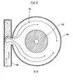
- 10 designates a pressure reducing device. It comprises a first wider transport channel 12 and a second narrower transport channel 14, that is, an upstream transport channel with a larger outside diameter than the downstream transport channel.
- the pressure reducing device 10 comprises two concentric cylinders 16 and 18, respec tively.
- the cylinder 16 is closed at one end 20.
- the cylinder 18 is placed in the cylinder 16 near the closed end 20 thereof thus defining a space 22.
- At the end of the cylinder 18 facing the space 20 there is a nozzle 24 with an opening 26 with an area F 1 , which is considerably smaller than the area F 2 in the channel 14 into which the opening 26 opens out.
- the opposite end of the cylinder 18 is closed by a lid 28 thereby forming an appendix-like blind space 30.
- the lid 28 is constructed so as to be resistant to erosion by the inrushing particulate material.
- the cylinder 18 is connected to a radial outlet tube 32, suitably disposed near the nozzle 24.
- Particulate material flows in the annular transport channel 12, as shown by the arrows 34, down into the space 22 where it is bent 180°, as shown by the arrows 36, on its way into the opening 26.
- Solid material is thrown up into the blind space 30, in the innermost part of which a cushion 38 of material is formed protecting the lid 28 from erosion.
- Particulate material and transport gas leave the transport channel 14 through the tube 32.
- the inlet side of the nozzle 24, which faces the space 22, is shaped so that in a radial section its generatrix 40 is arcuated.
- This generatrix 40 may, for example, in part describe an ellipse or a circle. With a suitable arcuate shape such flow conditions are obtained that the particle concentration is lower in the peripheral area of the nozzle opening 26 than in its central area.
- larger particles 42 which are the most dangerous with regard to erosion, are concentrated in the central area of the opening 26 whereas smaller particles 44 will flow to a greater extent in the outer area of the opening, as shown in Figure 2. This effect is achieved by the 180 bend and a suitable shape of the generatrix 40.
- the opening 26 opens out into the transport channel 14 having a much larger cross-sectional area than the opening 26, the pressure loss will be very great and the desired pressure fall can be obtained with one single or few series-connected pressure reducing devices. Pressure drops exceeding 0.1 MPa (1 bar) can be achieved in a pressure reducing device of suitable design.
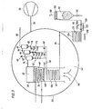
- numeral 50 designates a container under pressure.
- the space 52 is supplied with compressed air from a compressor 54 via a conduit 56.
- the container 50 accommodates a combustion chamber 58 and a number of parallel-connected groups 60, only one of which is shown, of series-connected dust separators 62, 64 and 66, for example cyclones, for the separation of dust from the combustion gases generated in the combustion chamber 58.
- the lower part of the combustion chamber 58 includes a fluidizable bed 68 of granular material and a tube nest 70 for cooling the bed 68 and for generating steam for a steam turbine (not shown).
- the combustion gases leaving the bed 68 accumulate in the freeboard 72 above the bed 68 and are passed through the conduit 74 to the first dust separator 62, for example a cyclone, and thereafter further to the series-connected dust separators 64.and 66 through the conduits 76 and 78. Dust (ashes) is separated in the dust separators 62, 64 and 66.
- the cleaned gases leaving the dust separator 66 are led to a gas turbine (not shown) via the conduit 80. This gas turbine can drive the compressor-54 and/or a generator.
- Dust 82 separated in the dust separators are continuously transported away in a pneumatic transportation system.
- This system comprises conduits 84, 86, 88, a common collecting conduit 90 which is connected to a cooler 92 for cooling dust and transport gas, a conduit 94, and a container 96 where dust is separated from the transport gas.
- the container 96 is situated outside the pressure vessel 50. Dust is discharged via the valve 98. Transport air 100 is removed via a filter 102 to the atmosphere.
- the cooler 92 may be de-. signed as the transport device according to the above-mentioned EP-A-83306073.4, whereby the pressure is successively reduced by repeatedly diverting the gas/dust flow between a number of series-connected tube parts.
- the cooler 92 may be placed in a channel 104 which conducts combustion air 106 from the space 52 in the pressure vessel 50 to the nozzles 108 in the bottom 110 of the combustion chamber 58.
- Figure 3 shows three series-connected pressure reducing devices 112a - 112c in the conduit 84, two series-connected pressure reducing devices 114a and 114b in the conduit 86, one pressure reducing device 116 in the conduit 88, and two pressure reducing devices 118a and 118b in the conduit 94.
- the total throttling ability may vary both by constructing pressure reducing devices with different throttling ability and by connecting in series different numbers of pressure reducing devices 118 having equal or different throttling ability.
- a bypass conduit 120 with a valve 122 may be provided parallel to the pressure reducing devices 118.
- the pressure reducing devices 118 and the bypass conduit 120 with the valve 122 may be located inside the pressure vessel 50 or, as in Figure 3, outside this vessel.
- a second cooler 124 in a channel 126, through which cooling air is injected by means of a fan 128. Possibly, this latter cooler 124 may replace the pressure reducing devices 118.
- the second cooler 124 may be used when it is not possible to obtain sufficient cooling by means of the combustion air down to a desired temperature of at most 150° C prior to entry into the container 96.
- the pressure reducing devices 112, 114 and 116 in the PFBC plant are designed in the same way as the pressure reducing device 10.
- the cylinder 16 of the pressure reducing device 114a is - as shown in Figure 4 - directly connected to the lower conical part 64a of the dust separator 64.
- the nozzle 24 has a larger outer diameter than the cylinder 18 so that a constriction arises in the channel portion 12a. This can affect the flow at the nozzle inlet.
- the nozzle 24 has a greater axial extension than in the embodiment according to Figure 1.
- the nozzle is connected to a tube 130, so that a flow path with a constant cross-section and a considerable length is obtained.
- nozzles 132 are provided in the lower part of the space 22, through which nozzles gas may be supplied to the space 22 fluidizing the downfalling dust which has been separated in the dust separator 64.
- air from the space 52 can be utilized since the pressure here exceeds the pressure in the space 22.
- the air is supplied through the conduit 134.
- an adjustable throttle means 136 is provided for determining the air quantity in this conduit.
- the dust/gas flow flows over from the pressure reducing device 114a to the pressure reducing device 114b through the outlet conduit 32a.
- the dust/gas flow leaves the pressure reducing device 114b through the outlet tube 32b being connected to the conduit 86.
- the pressure reducing device may also be included in a feed- ing-out conduit for bed material from the fluidized bed in a PFBC power plant.
- a cooler In front of the pressure reducing device there is suitably placed a cooler, in which the bed material is cooled prior to passage through valves in the conveying pipe.
- first container 140 filled with, for example, crushed coal 142.
- the container 140 is constantly under atmospheric pressure. It is connected via the conduit 144 with the valve 146 to the container 148.
- the container 148 in its turn, communicates with the container 150 via the conduit 152 with the valve 154.
- the container 150 is connected, via the conduit 156 with the rotary feeder 158, to the ejector 160 in the fuel conveying pipe 162.
- the ejector is supplied with transport gas from the compressor 164 through the conduit 166.
- the containers 148 and 150 communicate with the gas conduit 166 via the conduits 168, 170 and 168, 172, respectively.
- the conduit 172 includes a valve 174.
- the container 148 can be connected to the atmosphere through a conduit 176 with a valve 178 and a pressure reducing device 10.
- the valves 146 and 178 are closed and the valve 174 opened, thus pressurizing the container 148.
- the valve 154 is then opened, and the material is transferred to the container 150, whereupon the valve 154 is closed again. Thereafter, the pressure is reduced by opening the valve 178.
- the flow is throttled in the pressure reducing device 10 to obtain suitable outflow conditions.
- the valve 178 may be an on-off valve, wh-ch is most advantageous since the gas in the container is contaminated by solid abrasive particles. Because of the pressure reducing device the valve can be formed with a large flow area, resulting in a low velocity of flow and, hence, in a small erosion by the solid particles in the gas.
- Figure 6 shows the pressure reducing device 10 placed after a valve 181 in a conduit 180 from a natural gas source 182.
- the pressure of the gas in the gas source may amount to several hundred bar, and therefore it needs reducing before the gas is released into a conveying pipe.
- the pressure reducing device according to the invention is extremely suitable for this purpose, since it is very insensitive to solid impurities which accompany the gas. Also in this case, of course, a plurality of pressure reducing devices may be connected in series, as shown in Figure 4.
- the pressure reducing device according to the invention can also be used in a blast nozzle for accelerating the blast material to a high speed.
- a housing 190 accommodates a nozzle 192.
- Compressed air and blast material are supplied to the space 194 through the conduit 196.
- the material/gas flow is diverted, as shown by the paths 198a to 198c.
- Small particles with a small mass require little power to be diverted and follow an narrowly arcuated inner path 198a.
- a heavier mass requires more power and follows a middle path 198b, and the heaviest particles follow an outer path 198c.
- a sleeve 202 may be arranged which has a considerably larger diameter than the opening 200. Since the main part of the blasting material passes through the nozzle without contacting its walls, the wear of the nozzle is insignificant so that the nozzle will have a much longer life than blast nozzles used in the state of the art.
- a uniform blasting effect can be obtained during a long pe- riod of time. This is an-extremely great advantage in the case of automated blasting by means of a robot.
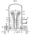
- FIG. 9 shows a preferred practical embodiment of the pressure reducing device.
- the first transport channel 12 is here formed as a cup-shaped housing 202 and a nozzle 24 composed of several parts, and the second transport channel 14 is formed of a tube 204.
- the first channel 12 is thus annular.
- the housing 202 is formed with a flange 206 and joined to the flange 210 of the tube 204 by means of the flange 206 and bolts 208.
- a gas/particle flow is supplied to the pressure reducing device via a tube 212 which is tangentially connected to the housing 202.
- the nozzle 24 is built up of a sleeve 214 with an outer flange 216 and an inner flange 218, a tube 220 extending down into the sleeve 214, said tube 220 resting on the inner flange 218 and being sealed against the sleeve 214 by an O-ring 222.
- a ring 224 is joined to the sleeve 214 by a number of bolts 226, the ring thereby fixing the nozzle 220 in the sleeve 214.
- the nozzle 24 is joined to the housing 202 by the flange 216 of the sleeve 214 and a number of bolts 228.
- the embodiment according to Figure 9 is very favourable.
- the nozzle 220 and the ring 224 which are subjected to the greatest stresses, can be made from a material with great resistance to wear, for example from a metal alloy having good wear resistance, a hard metal (cemented carbides), or a ceramic material.
- the consumption of expensive material is limited, and the parts which are worst exposed to wear can be replaced.
- the embodiment is advantageous with regard to manufacture, cost and service.
Landscapes
- Engineering & Computer Science (AREA)
- Mechanical Engineering (AREA)
- Chemical & Material Sciences (AREA)
- General Engineering & Computer Science (AREA)
- Combustion & Propulsion (AREA)
- Manufacturing & Machinery (AREA)
- Materials Engineering (AREA)
- Metallurgy (AREA)
- Organic Chemistry (AREA)
- Air Transport Of Granular Materials (AREA)
- Cyclones (AREA)
Priority Applications (1)
| Application Number | Priority Date | Filing Date | Title |
|---|---|---|---|
| AT86100806T ATE42726T1 (de) | 1985-01-28 | 1986-01-22 | Druckreduzierungsanordnung fuer eine vorrichtung zum pneumatischen foerdern von koernigen guetern. |
Applications Claiming Priority (2)
| Application Number | Priority Date | Filing Date | Title |
|---|---|---|---|
| SE8500378A SE458924B (sv) | 1985-01-28 | 1985-01-28 | Transportanordning foer pneumatisk transport med tryckreduceringsorgan innefattande strypning |
| SE8500378 | 1985-01-28 |
Publications (2)
| Publication Number | Publication Date |
|---|---|
| EP0192073A1 true EP0192073A1 (de) | 1986-08-27 |
| EP0192073B1 EP0192073B1 (de) | 1989-05-03 |
Family
ID=20358917
Family Applications (1)
| Application Number | Title | Priority Date | Filing Date |
|---|---|---|---|
| EP86100806A Expired EP0192073B1 (de) | 1985-01-28 | 1986-01-22 | Druckreduzierungsanordnung für eine Vorrichtung zum pneumatischen Fördern von körnigen Gütern |
Country Status (6)
| Country | Link |
|---|---|
| US (1) | US4802796A (de) |
| EP (1) | EP0192073B1 (de) |
| JP (1) | JPH0729692B2 (de) |
| AT (1) | ATE42726T1 (de) |
| DE (1) | DE3663129D1 (de) |
| SE (1) | SE458924B (de) |
Cited By (1)
| Publication number | Priority date | Publication date | Assignee | Title |
|---|---|---|---|---|
| EP0287812A1 (de) * | 1987-03-25 | 1988-10-26 | ASEA STAL Aktiebolag | Kraftwerk zum Verbrennen von Brennstoff in einem Wirbelbett |
Families Citing this family (4)
| Publication number | Priority date | Publication date | Assignee | Title |
|---|---|---|---|---|
| SE500098C2 (sv) * | 1992-10-07 | 1994-04-18 | Abb Carbon Ab | Sätt och anordning för utmatning av kornformigt material från en trycksatt behållare |
| US5899641A (en) * | 1996-03-01 | 1999-05-04 | The Young Industries | Bulk material conveying system and ejector therefor |
| SE9800033L (sv) * | 1998-01-09 | 1999-05-31 | Paer Wellmar | Förfarande och anläggning för pneumatisk transport av fasta partiklar |
| IT1397049B1 (it) | 2009-12-24 | 2012-12-28 | Wam Spa | Apparecchiatura di caricamento di un silo |
Citations (2)
| Publication number | Priority date | Publication date | Assignee | Title |
|---|---|---|---|---|
| WO1983003557A1 (en) * | 1982-04-19 | 1983-10-27 | Saunders, David, Henry | Abrasive fluid jet apparatus |
| EP0108505A1 (de) * | 1982-10-08 | 1984-05-16 | ASEA Stal Aktiebolag | Apparat zum Fördern von teilchenförmigem Material aus einem Druckbehälter |
Family Cites Families (10)
| Publication number | Priority date | Publication date | Assignee | Title |
|---|---|---|---|---|
| US610066A (en) * | 1898-08-30 | Grain-chute | ||
| US914105A (en) * | 1908-06-11 | 1909-03-02 | Francis P Boland | Sand-blast machine. |
| US2606097A (en) * | 1947-08-25 | 1952-08-05 | Phillips Petroleum Co | Fluid type catalytic reaction chamber and method of operating same |
| US2693395A (en) * | 1949-08-20 | 1954-11-02 | Union Oil Co | Solids conveyance |
| US2610093A (en) * | 1950-12-22 | 1952-09-09 | Sun Oil Co | Pneumatic lift conduit |
| US2901421A (en) * | 1952-07-12 | 1959-08-25 | Socony Mobil Oil Co Inc | Method and apparatus for transfer of contact materials |
| DE1152948B (de) * | 1960-05-31 | 1963-08-14 | Zd Y Na Vyrobu Vzduchotechnick | Einrichtung zum Auflockern und Herausfoerdern von schuettfaehigem Gut aus einem Aufnahmebehaelter |
| ATE3946T1 (de) * | 1978-08-22 | 1983-07-15 | Siemens Aktiengesellschaft | Vorrichtung zum untersuchen oder regeln einer erhoehten herzfrequenz. |
| JPS60292A (ja) * | 1983-06-17 | 1985-01-05 | Mitsubishi Plastics Ind Ltd | ホツトプレスの加熱冷却装置 |
| SE444427B (sv) * | 1983-10-31 | 1986-04-14 | Stal Laval Turbin Ab | Pneumatiskt transportsystem med omkopplingsventil |
-
1985
- 1985-01-28 SE SE8500378A patent/SE458924B/sv not_active IP Right Cessation
-
1986
- 1986-01-22 EP EP86100806A patent/EP0192073B1/de not_active Expired
- 1986-01-22 AT AT86100806T patent/ATE42726T1/de not_active IP Right Cessation
- 1986-01-22 DE DE8686100806T patent/DE3663129D1/de not_active Expired
- 1986-01-27 JP JP61015564A patent/JPH0729692B2/ja not_active Expired - Lifetime
-
1987
- 1987-09-29 US US07/104,590 patent/US4802796A/en not_active Expired - Fee Related
Patent Citations (2)
| Publication number | Priority date | Publication date | Assignee | Title |
|---|---|---|---|---|
| WO1983003557A1 (en) * | 1982-04-19 | 1983-10-27 | Saunders, David, Henry | Abrasive fluid jet apparatus |
| EP0108505A1 (de) * | 1982-10-08 | 1984-05-16 | ASEA Stal Aktiebolag | Apparat zum Fördern von teilchenförmigem Material aus einem Druckbehälter |
Cited By (1)
| Publication number | Priority date | Publication date | Assignee | Title |
|---|---|---|---|---|
| EP0287812A1 (de) * | 1987-03-25 | 1988-10-26 | ASEA STAL Aktiebolag | Kraftwerk zum Verbrennen von Brennstoff in einem Wirbelbett |
Also Published As
| Publication number | Publication date |
|---|---|
| SE8500378D0 (sv) | 1985-01-28 |
| ATE42726T1 (de) | 1989-05-15 |
| DE3663129D1 (en) | 1989-06-08 |
| SE8500378L (sv) | 1986-07-29 |
| JPH0729692B2 (ja) | 1995-04-05 |
| EP0192073B1 (de) | 1989-05-03 |
| JPS61174030A (ja) | 1986-08-05 |
| US4802796A (en) | 1989-02-07 |
| SE458924B (sv) | 1989-05-22 |
Similar Documents
| Publication | Publication Date | Title |
|---|---|---|
| US7048782B1 (en) | Apparatus and process for power recovery | |
| WO1989000660A1 (en) | Circulating fluidized bed reactor | |
| US4655147A (en) | Plant for the combustion of particulate fuel in a fluidized bed | |
| KR20100126290A (ko) | 미립 내지 조립 고체를 수용하여 컨테이너로부터 고압 시스템으로 전달하기 위한 방법 및 장치 | |
| US4699210A (en) | Apparatus for conveying particulate material from a pressurized container | |
| US4730563A (en) | Power plant with centrifugal separators for returning material from combustion gases to a fluidized bed | |
| UA126981C2 (uk) | Сушильний бункер, а також розмельно-сушильний комплекс, який включає в себе такий бункер | |
| EP0192073B1 (de) | Druckreduzierungsanordnung für eine Vorrichtung zum pneumatischen Fördern von körnigen Gütern | |
| US2650675A (en) | Method and apparatus for the separation of particulate material from entraining gaseos fluids | |
| US4619562A (en) | Pneumatic transportation system for powdered or granular material with a switching valve for selection of different transport paths | |
| US4756257A (en) | Power plant with centrifugal type cleaners for combustion gases | |
| JP3422571B2 (ja) | フィルタ下部ホッパからの粉体輸送装置 | |
| US4767243A (en) | Pneumatic conveying system with directional change of a gas/particulate material stream | |
| US5122171A (en) | Apparatus for separating particulate material from hot gas | |
| US3067990A (en) | Apparatus for preheating finely divided material | |
| JPH09847A (ja) | 粉体冷却輸送方法 | |
| EP0264735B1 (de) | Zyklon zum Abscheiden von Feststoffteilchen aus einem Gas | |
| US4593478A (en) | Pressure-reducing valve | |
| US5176475A (en) | Transfer chambers for the conveyor in a pneumatic transport system | |
| US4936716A (en) | Transport device for pneumatically transporting particulate material from a container under high pressure to a container under low pressure | |
| JPH0742910A (ja) | 加圧流動床ボイラの灰処理装置 | |
| JP4364321B2 (ja) | 二段サイクロンシステム | |
| CA1121743A (en) | Gas/particle separating device | |
| SE455342B (sv) | Utmatningsanordning for utmatning av pulverformigt eller kornformigt gods fran en trycksatt behallare | |
| SE440269B (sv) | Materialtransportanordning i anleggning for forbrenning i fluidiserad bedd |
Legal Events
| Date | Code | Title | Description |
|---|---|---|---|
| PUAI | Public reference made under article 153(3) epc to a published international application that has entered the european phase |
Free format text: ORIGINAL CODE: 0009012 |
|
| AK | Designated contracting states |
Kind code of ref document: A1 Designated state(s): AT BE CH DE FR GB IT LI LU NL SE |
|
| 17P | Request for examination filed |
Effective date: 19870223 |
|
| 17Q | First examination report despatched |
Effective date: 19871228 |
|
| GRAA | (expected) grant |
Free format text: ORIGINAL CODE: 0009210 |
|
| AK | Designated contracting states |
Kind code of ref document: B1 Designated state(s): AT BE CH DE FR GB IT LI LU NL SE |
|
| REF | Corresponds to: |
Ref document number: 42726 Country of ref document: AT Date of ref document: 19890515 Kind code of ref document: T |
|
| REF | Corresponds to: |
Ref document number: 3663129 Country of ref document: DE Date of ref document: 19890608 |
|
| ITF | It: translation for a ep patent filed | ||
| EN | Fr: translation not filed | ||
| ET | Fr: translation filed | ||
| REG | Reference to a national code |
Ref country code: FR Ref legal event code: BR |
|
| PLBE | No opposition filed within time limit |
Free format text: ORIGINAL CODE: 0009261 |
|
| STAA | Information on the status of an ep patent application or granted ep patent |
Free format text: STATUS: NO OPPOSITION FILED WITHIN TIME LIMIT |
|
| 26N | No opposition filed | ||
| ITTA | It: last paid annual fee | ||
| PGFP | Annual fee paid to national office [announced via postgrant information from national office to epo] |
Ref country code: AT Payment date: 19920109 Year of fee payment: 7 |
|
| PGFP | Annual fee paid to national office [announced via postgrant information from national office to epo] |
Ref country code: LU Payment date: 19920127 Year of fee payment: 7 |
|
| PGFP | Annual fee paid to national office [announced via postgrant information from national office to epo] |
Ref country code: NL Payment date: 19920131 Year of fee payment: 7 |
|
| PGFP | Annual fee paid to national office [announced via postgrant information from national office to epo] |
Ref country code: BE Payment date: 19920309 Year of fee payment: 7 |
|
| EPTA | Lu: last paid annual fee | ||
| PG25 | Lapsed in a contracting state [announced via postgrant information from national office to epo] |
Ref country code: LU Free format text: LAPSE BECAUSE OF NON-PAYMENT OF DUE FEES Effective date: 19930122 Ref country code: AT Effective date: 19930122 |
|
| PG25 | Lapsed in a contracting state [announced via postgrant information from national office to epo] |
Ref country code: BE Effective date: 19930131 |
|
| BERE | Be: lapsed |
Owner name: ASEA STAL A.B. Effective date: 19930131 |
|
| PG25 | Lapsed in a contracting state [announced via postgrant information from national office to epo] |
Ref country code: NL Effective date: 19930801 |
|
| NLV4 | Nl: lapsed or anulled due to non-payment of the annual fee | ||
| EAL | Se: european patent in force in sweden |
Ref document number: 86100806.8 |
|
| PGFP | Annual fee paid to national office [announced via postgrant information from national office to epo] |
Ref country code: DE Payment date: 19991231 Year of fee payment: 15 |
|
| PGFP | Annual fee paid to national office [announced via postgrant information from national office to epo] |
Ref country code: SE Payment date: 20000107 Year of fee payment: 15 |
|
| PGFP | Annual fee paid to national office [announced via postgrant information from national office to epo] |
Ref country code: FR Payment date: 20000112 Year of fee payment: 15 |
|
| PGFP | Annual fee paid to national office [announced via postgrant information from national office to epo] |
Ref country code: GB Payment date: 20000119 Year of fee payment: 15 |
|
| PGFP | Annual fee paid to national office [announced via postgrant information from national office to epo] |
Ref country code: CH Payment date: 20000127 Year of fee payment: 15 |
|
| PG25 | Lapsed in a contracting state [announced via postgrant information from national office to epo] |
Ref country code: GB Free format text: LAPSE BECAUSE OF NON-PAYMENT OF DUE FEES Effective date: 20010122 |
|
| PG25 | Lapsed in a contracting state [announced via postgrant information from national office to epo] |
Ref country code: SE Free format text: LAPSE BECAUSE OF NON-PAYMENT OF DUE FEES Effective date: 20010123 |
|
| PG25 | Lapsed in a contracting state [announced via postgrant information from national office to epo] |
Ref country code: LI Free format text: LAPSE BECAUSE OF NON-PAYMENT OF DUE FEES Effective date: 20010131 Ref country code: CH Free format text: LAPSE BECAUSE OF NON-PAYMENT OF DUE FEES Effective date: 20010131 |
|
| EUG | Se: european patent has lapsed |
Ref document number: 86100806.8 |
|
| GBPC | Gb: european patent ceased through non-payment of renewal fee |
Effective date: 20010122 |
|
| REG | Reference to a national code |
Ref country code: CH Ref legal event code: PL |
|
| PG25 | Lapsed in a contracting state [announced via postgrant information from national office to epo] |
Ref country code: FR Free format text: LAPSE BECAUSE OF NON-PAYMENT OF DUE FEES Effective date: 20010928 |
|
| PG25 | Lapsed in a contracting state [announced via postgrant information from national office to epo] |
Ref country code: DE Free format text: LAPSE BECAUSE OF NON-PAYMENT OF DUE FEES Effective date: 20011101 |
|
| REG | Reference to a national code |
Ref country code: FR Ref legal event code: ST |
|
| PG25 | Lapsed in a contracting state [announced via postgrant information from national office to epo] |
Ref country code: IT Free format text: LAPSE BECAUSE OF NON-PAYMENT OF DUE FEES;WARNING: LAPSES OF ITALIAN PATENTS WITH EFFECTIVE DATE BEFORE 2007 MAY HAVE OCCURRED AT ANY TIME BEFORE 2007. THE CORRECT EFFECTIVE DATE MAY BE DIFFERENT FROM THE ONE RECORDED. Effective date: 20050122 |