EP0191984B1 - Dispositif d'entraînement du papier dans une imprimante - Google Patents
Dispositif d'entraînement du papier dans une imprimante Download PDFInfo
- Publication number
- EP0191984B1 EP0191984B1 EP85308867A EP85308867A EP0191984B1 EP 0191984 B1 EP0191984 B1 EP 0191984B1 EP 85308867 A EP85308867 A EP 85308867A EP 85308867 A EP85308867 A EP 85308867A EP 0191984 B1 EP0191984 B1 EP 0191984B1
- Authority
- EP
- European Patent Office
- Prior art keywords
- platen
- feed mechanism
- guide
- pin feed
- pair
- Prior art date
- Legal status (The legal status is an assumption and is not a legal conclusion. Google has not performed a legal analysis and makes no representation as to the accuracy of the status listed.)
- Expired
Links
Images


Classifications
-
- B—PERFORMING OPERATIONS; TRANSPORTING
- B41—PRINTING; LINING MACHINES; TYPEWRITERS; STAMPS
- B41J—TYPEWRITERS; SELECTIVE PRINTING MECHANISMS, i.e. MECHANISMS PRINTING OTHERWISE THAN FROM A FORME; CORRECTION OF TYPOGRAPHICAL ERRORS
- B41J11/00—Devices or arrangements of selective printing mechanisms, e.g. ink-jet printers or thermal printers, for supporting or handling copy material in sheet or web form
- B41J11/48—Apparatus for condensed record, tally strip, or like work using two or more papers, or sets of papers, e.g. devices for switching over from handling of copy material in sheet form to handling of copy material in continuous form and vice versa or point-of-sale printers comprising means for printing on continuous copy material, e.g. journal for tills, and on single sheets, e.g. cheques or receipts
-
- B—PERFORMING OPERATIONS; TRANSPORTING
- B41—PRINTING; LINING MACHINES; TYPEWRITERS; STAMPS
- B41J—TYPEWRITERS; SELECTIVE PRINTING MECHANISMS, i.e. MECHANISMS PRINTING OTHERWISE THAN FROM A FORME; CORRECTION OF TYPOGRAPHICAL ERRORS
- B41J11/00—Devices or arrangements of selective printing mechanisms, e.g. ink-jet printers or thermal printers, for supporting or handling copy material in sheet or web form
- B41J11/26—Pin feeds
- B41J11/30—Pin traction elements other than wheels, e.g. pins on endless bands
-
- B—PERFORMING OPERATIONS; TRANSPORTING
- B65—CONVEYING; PACKING; STORING; HANDLING THIN OR FILAMENTARY MATERIAL
- B65H—HANDLING THIN OR FILAMENTARY MATERIAL, e.g. SHEETS, WEBS, CABLES
- B65H20/00—Advancing webs
- B65H20/20—Advancing webs by web-penetrating means, e.g. pins
Definitions
- This invention relates to a paper feed device for a printer of the type which includes a pin feed mechanism for feeding a sprocket paper web having pin holes formed therein.
- a pin feed mechanism 4 is mounted for pivotal motion about a support shaft 5 between a drawing or pulling position.
- a pair of guide plates 8 and 8a for guiding a sprocket paper web 7 extends from individual positions behind and below the pin feed mechanism 4 toward different positions below a platen 3.
- a pinch roller 9 is mounted for movement into and out of engagement with the platen 3. As seen in Figure 5, when printing on a cut sheet 11 is to be effected, the pinch roller 9 is pressed against the platen 3 to feed the cut sheet 11.
- the cut sheet 11 may be disclocated from a contact point between the platen 3 and the pinch roller 9 and float from the platen 3 so that it may be caught by a border between the pinch roller 9 and the guide plate 8. Accordingly, the position of a leading edge of the cut sheet 11 will become unstable, and hence even if the platen 3 is rotated a predetermined fixed angle, the print starting position of the cut sheet 11 cannot be determined. Besides, the cut sheet 11 may be caught by an end 8b of the guide plate 8a, and hence it is difficult to insert the cut sheet 11.
- Further conventional pin feed mechanisms include a pair of left and right holders fitted both for sliding motion on a drive shaft and a guide shaft.
- a rotary member is mounted on each of the holders and has a plurality of projections around an outer periphery thereof, such as a pin wheel or a belt, whereby the rotary members are driven by the drive shaft to feed a paper web having a pair of rows of feed holes formed along opposite edges thereof.
- the guide shaft and the drive shaft are mounted at opposite ends thereof on a pair of left and right support plates.
- the holders are pivoted upwardly or downwardly around the guide shaft between and are either disposed in a drawing position for drawing paper from an upper portion of an outer periphery of the platen, or in a pushing or forcing position for pushing paper to a lower portion of the outer periphery of the platen.
- a pin feed mechanism which is alternatively positioned between a drawing position and a pushing position is handled as a standard equipment. Accordingly, such a pin feed mechanism is of limited use, and expensive to a user who does not require pin feed but actually friction feed.
- DE-A-3,036,642 provides a paper feed device for a printer having a platen comprising:-
- the present invention starts from a known paper feed device shown in Figures 6 and 7 of this application and is characterised in that the pin feed mechanism is either operable in its lower position to feed a web to the platen, the pinch rollers being retracted from the platen, or the pinch rollers contact the platen to feed a sheet thereto independent of the pin feed mechanism.
- the present invention provides a paper feed device for a printer, comprising a pin feed mechanism mounted for changing over movement between a pushing position and a drawing position, a guide plate for guiding sprocket paper to a platen from a position rearwardly of the pin feed mechanism in the pushing position, a pinch roller mounted in the guide plate for movement toward and away from the platen, a movable guide plate for guiding a cut sheet from between a front face of the pin feed mechanism and the platen to a contact point between the platen and the pinch roller, a pair of arms pivotally supported at opposite side ends of the movable guide plate, and supporting means located on opposite sides of the pin feed mechanism, the supporting means retracting the movable guide plate upwardly when the pin feed mechanism is changed over to the drawing position.
- the pin feed mechanism is selectively positioned either to the pushing position or to the drawing position.
- the movable guide plate guides the sprocket paper web to the platen while it guides a cut sheet to the contact point between the platen and the pinch roller.
- the pin feed mechanism is changed over to the drawing position, the movable guide plate is retracted upwardly. Accordingly, the sprocket paper web inserted along the guide plate can be fed smoothly by cooperation of the pinch roller with the platen until it is caught by the pin feed mechanism.
- a paper feed device for a printer which comprises a frame having a recess formed therein for receiving a guide shaft of a pin feed mechanism therein, the frame having a flexible piece provided thereon, the flexible piece having a pressing face adapted to resiliently contact with an end face of the guide shaft, the flexible piece further having a projection for pressing the guide shaft against the bottom of the recess of the frame, and a spring plate mounted on the frame and having engaging portions for resiliently engaging with part of a support member which supports ends of the guide shaft and a drive shaft.
- the pin feed mechanism can be assembled and disassembled very easily.
- the support member can be selectively positioned between the drawing position and the pushing in position together with the support member.
- the spring plate has up to three engaging portions for engaging with the support member and when the support member is engaged with a mid one of the three engaging portions, a drive force is not transmitted to the pin feed mechanism, and hence the load can be reduced.
- a print head 2 and a platen 3 are mounted on a frame 1, and a pin feed mechanism is mounted for pivotal motion around a support shaft 5 between a lower or pushing position (Figure 1) and an upper or drawing position ( Figure 2).
- the pin feed mechanism 4 includes a drive shaft 6 which is driven by a motor to feed a sprocket paper web 7.
- a guide plate 8 is provided to guide the sprocket paper web 7 from a position below and rearward of the pin feed mechanism 4 and is arranged so that it does not interfere with the pin feed mechanism 4 in the pushing position.
- a pair of pinch rollers 9 and 10 are mounted for movement toward and away from the platen 3 through the guide plate 8.
- a movable guide plate 12 is additionally provided for guiding a cut sheet 11 from between a front face of the pin feed mechanism 4 and an upper part of the platen 3 to a contact point between the platen 3 and the pinch roller 9 when the pinch rollers 9 and 10 are contacted with the platen 3.
- the movable guide plate 12 has formed therein a recess 13 for accomodating the pinch roller 9 therein and has formed thereon an arm 14 which is pivotally held around each end of a shaft 3a of the platen 3.
- a support 16 in the form of a plate is secured to each side of the pin feed mechanism 4, that is, to each one of a pair of plates 15 provided for supporting the support shaft 5 and the drive shaft 6.
- the supports 16 have each formed therein a guideway 18 in which a pin 17 extending from the arm 14 is supported.
- Printing at the pushing position of the pin feed mechanism in Figure 1 using a sprocket paper web 7 can also be effected.
- the pinch rollers 9 and 10 are retracted from their respective positions as described above and the sprocket paper web 7 which has been pushed to the platen 3 is guided by the movable guide plate 12.
- the movable guide plate 12 operates in response to a changing over operation of the pin feed mechanism 4 between the drawing and pushing positions, operation error can be prevented.
- a second embodiment of the present invention will now be described with reference to Figures 8 to 15.
- the guide plate 12 is not shown in these embodiments which describe the form of the pin feed mechanism.
- a paper pan 23 is supported on a pair of left and right frames 21 and 22.
- a pin feed mechanism 24 includes a drive shaft 25, a guide shaft 26, a pair of left and right holders 27 fitted for sliding movement on the shafts 25 and 26, a rotary member 28 in the form of a belt supported for rotation on each of the holders 27, a paper holder 29 mounted for rising and falling movement on each of the holders 27, and a pair of left and right support members 30 and 31.
- the support members 30 and 31 have integrally formed thereon a cylindrical portion 32 which is adapted to be inter-fitted with the guide shaft 26; and a bushing 33 for rotatably supporting the drive shaft 25 therein.
- a flange 34 is formed at an end of the bushing 33.
- the bushing 33 has formed at the cylindrical portion 32 thereof a recess 36 which is adapted to engage with a pin 35 mounted on the guide shaft 26 to hold the bushing 33 against rotation; and a pawl 38 which is adapted to resiliently engage with a groove 37 formed around the guide shaft 26.
- the frames 21 and 22 have integrally formed thereon a recess 39 for supporting either end of the guide shaft 26, another recess 40 for receiving the bushing 33 therein, a flexible piece 41 mounted in opposing relationship to either end of the guide shaft 26, a stopper 42 for preventing the flexible piece 41 from being excessively bent in an outward direction, and a pair of catches 43 located above and below the recess 40.
- the flexible piece 41 has a pressing face 44 and a projection 45 integrally formed thereon.
- a spring plate 46 is held at opposite upper and lower ends thereof by the catches 43 and has engaging portions 47, 48 and 49 formed thereon which are adapted to resiliently engage with part of the support member 30 or 31, that is, the bushing 33.
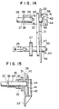
- the frame 22 supports thereon a motor 50, a train of gears 51, 52 and 53 for serially transmitting rotation of the motor 50 to a platen gear 54, an idler gear 55 for transmitting rotation of the platen gear 54 to an input gear 57 secured to an end of the drive shaft 25, and another idler gear 56 for transmitting rotation of the gear 52 to the input gear 57.
- the platen gear 54 is secured to an end of a platen 58.
- the bushings 33 are inserted into the recesses 40 and engaged with the spring plates 46, and then the guide shaft 26 is pushed into the recesses 39.
- the flexible pieces 41 are deflected outwardly to allow the guide shaft 26 to enter below the projections 45.
- the guide shaft 26 is thus pressed against the bottoms of the recesses 39 by the projections 45 while movement of the guide shaft 26 in the thrust direction is prevented by the pressing faces 44 of the flexible pieces 41. If the flexible pieces 41 are deflected outwardly, the pin feed mechanism 24 can be readily disassembled from the frames 21 and 22.
- the pinch roller 60 may be contacted with the platen 58 to effect friction feeding.
- the bushings 33 are engaged with the mid engaging portions 48 of the spring plates 56 as seen in Figure 11.
- the input gear 57 is held in a position in which it is not engaged with either of the idler gears 55 and 56. Accordingly, the load to the motor 50 can be reduced.
- the pin feed mechanism 24 can be assembled and disassembled easily by a dealer or a user. Accordingly, the pin feed mechanism 24 can be treated as an option so that a user can buy it optionally.
- the structure of a mechanism for selectively positioning the support members 30 and 31 can be made very simple with the spring plate 46 added to the frame 22.
Landscapes
- Handling Of Sheets (AREA)
Claims (8)
Applications Claiming Priority (6)
| Application Number | Priority Date | Filing Date | Title |
|---|---|---|---|
| JP1984189983U JPS61105157U (fr) | 1984-12-14 | 1984-12-14 | |
| JP189983/84 | 1984-12-14 | ||
| JP1984189982U JPS61105156U (fr) | 1984-12-14 | 1984-12-14 | |
| JP189982/84 | 1984-12-14 | ||
| JP59267224A JPS61144370A (ja) | 1984-12-18 | 1984-12-18 | 印字機の紙送り装置 |
| JP267224/84 | 1984-12-18 |
Publications (2)
| Publication Number | Publication Date |
|---|---|
| EP0191984A1 EP0191984A1 (fr) | 1986-08-27 |
| EP0191984B1 true EP0191984B1 (fr) | 1989-08-02 |
Family
ID=27326258
Family Applications (1)
| Application Number | Title | Priority Date | Filing Date |
|---|---|---|---|
| EP85308867A Expired EP0191984B1 (fr) | 1984-12-14 | 1985-12-05 | Dispositif d'entraînement du papier dans une imprimante |
Country Status (4)
| Country | Link |
|---|---|
| US (1) | US4742946A (fr) |
| EP (1) | EP0191984B1 (fr) |
| KR (1) | KR910004032B1 (fr) |
| DE (1) | DE3571956D1 (fr) |
Families Citing this family (19)
| Publication number | Priority date | Publication date | Assignee | Title |
|---|---|---|---|---|
| US4780013A (en) * | 1986-05-02 | 1988-10-25 | Sakase Kagaku Kogyo Kabushiki Kaisha | Web feed tractor for printer |
| JPS6359565A (ja) * | 1986-08-30 | 1988-03-15 | Citizen Watch Co Ltd | プツシユ・プル共用プリンタ− |
| US4836430A (en) * | 1987-02-20 | 1989-06-06 | Tokai Kogyo Kabushiki Kaisha | Paper feed apparatus |
| DE3705856A1 (de) * | 1987-02-24 | 1988-09-01 | Mannesmann Ag | Vorrichtung fuer den papiertransport in einer bueromaschine, insbesondere in einem matrixdrucker |
| JP2724457B2 (ja) * | 1987-03-02 | 1998-03-09 | セイコープレシジョン株式会社 | プリンタの用紙搬送装置 |
| DE3806551C2 (de) * | 1987-03-02 | 1994-08-04 | Seikosha Kk | Drucker mit einer Traktoranordnung |
| JPS63299957A (ja) * | 1987-05-30 | 1988-12-07 | Copal Co Ltd | プリンタの紙送り装置 |
| JPH0616766Y2 (ja) * | 1987-12-25 | 1994-05-02 | シチズン時計株式会社 | プリンタトップカバー |
| DE3807809A1 (de) * | 1988-03-10 | 1989-09-21 | Philips Patentverwaltung | Bueromaschine, z. b. drucker |
| DE3807808A1 (de) * | 1988-03-10 | 1989-09-21 | Philips Patentverwaltung | Bueromaschine, z. b. drucker |
| DE3807807A1 (de) * | 1988-03-10 | 1989-09-21 | Philips Patentverwaltung | Bueromaschine, z. b. drucker |
| JPH0255169A (ja) * | 1988-08-20 | 1990-02-23 | Citizen Watch Co Ltd | 連続用紙・単票用紙両用プリンタ |
| DE3906611A1 (de) * | 1989-03-02 | 1990-09-06 | Philips Patentverwaltung | Anordnung zur verstellung eines druckers |
| US5037222A (en) * | 1989-08-29 | 1991-08-06 | Genicom Corporation | Printer and cartridge assembly therefor |
| JP2995782B2 (ja) * | 1990-02-19 | 1999-12-27 | セイコーエプソン株式会社 | プリンタ |
| JP2586691B2 (ja) * | 1990-05-24 | 1997-03-05 | 松下電器産業株式会社 | 紙送り装置 |
| US5139355A (en) * | 1991-05-16 | 1992-08-18 | Printek, Inc. | Printer with multi-tractor form shuttle |
| US5217312A (en) * | 1992-05-19 | 1993-06-08 | Lexmark International, Inc. | Single lever push/pull/park selector for printer forms tractor |
| JP4995932B2 (ja) * | 2010-03-12 | 2012-08-08 | 株式会社沖データ | 印刷装置 |
Family Cites Families (10)
| Publication number | Priority date | Publication date | Assignee | Title |
|---|---|---|---|---|
| DE3036642A1 (de) * | 1980-09-29 | 1982-05-13 | Philips Patentverwaltung Gmbh, 2000 Hamburg | Transportvorrichtung fuer papierbahnen in buchungsmaschinen |
| JPS5829446U (ja) * | 1981-08-20 | 1983-02-25 | セイコーエプソン株式会社 | プリンタの紙送り装置 |
| DD201008A1 (de) * | 1981-10-06 | 1983-06-29 | Helmut Altenburg | Transporteinrichtung fuer den vorschub randgelochter endlosformulare fuer schreib-oder druckwerke von bueromaschinen |
| CH655056A5 (de) * | 1982-04-20 | 1986-03-27 | Albert Rutishauser | Transportvorrichtung zum zufuehren perforierter aufzeichnungstraeger zu einer schreibwalze und verwendung der transportvorrichtung. |
| DE3226510C2 (de) * | 1982-07-15 | 1984-07-12 | Siemens AG, 1000 Berlin und 8000 München | Universelle Papiertransporteinrichtung für Einzelblätter und Endlospapier in Zeilendruckeinrichtungen |
| EP0099958B1 (fr) * | 1982-07-29 | 1986-04-30 | MANNESMANN Aktiengesellschaft | Dispositif pour l'alimentation en supports d'enregistrement d'un imprimante, en particulier une imprimante matricielle |
| US4479598A (en) * | 1982-08-05 | 1984-10-30 | Genicom Corporation | Friction feed tractor |
| JPS6083868A (ja) * | 1983-10-17 | 1985-05-13 | Nec Corp | プリンタ |
| US4616773A (en) * | 1984-04-27 | 1986-10-14 | Precision Handling Devices Inc. | Forms feeding apparatus |
| US4569468A (en) * | 1984-09-18 | 1986-02-11 | International Business Machines Corporation | Continuous forms feed tractor with multiple cut forms chutes |
-
1985
- 1985-12-05 DE DE8585308867T patent/DE3571956D1/de not_active Expired
- 1985-12-05 EP EP85308867A patent/EP0191984B1/fr not_active Expired
- 1985-12-06 KR KR1019850009164A patent/KR910004032B1/ko not_active IP Right Cessation
- 1985-12-10 US US06/806,816 patent/US4742946A/en not_active Expired - Lifetime
Also Published As
| Publication number | Publication date |
|---|---|
| KR910004032B1 (ko) | 1991-06-22 |
| EP0191984A1 (fr) | 1986-08-27 |
| KR860004744A (ko) | 1986-07-11 |
| US4742946A (en) | 1988-05-10 |
| DE3571956D1 (en) | 1989-09-07 |
Similar Documents
| Publication | Publication Date | Title |
|---|---|---|
| EP0191984B1 (fr) | Dispositif d'entraînement du papier dans une imprimante | |
| EP0258026B1 (fr) | Imprimante avec mécanisme d'alimentation du papier à fonctions multiples | |
| GB2271084A (en) | Paper storage and feeding in ink jet printers. | |
| EP0157076A2 (fr) | Système distributeur d'encre comportant une cassette de ruban réversible | |
| US4729683A (en) | Paper sheet feeding apparatus | |
| US4838535A (en) | Sheet feeding device with detachable holder means for thick cut sheets | |
| EP0175155B1 (fr) | Dispositif de traction de formulaires en bande continue, équipé d'un introducteur pour formulaires de formes multiples | |
| GB2226794A (en) | Disposition of components in selective printers with openable casings | |
| US4297045A (en) | Paper feed system for a typewriter or the like | |
| KR890000374Y1 (ko) | 프린터의 종이이송장치 | |
| EP0447162B1 (fr) | Imprimante thermique travaillant ligne par ligne | |
| GB2203700A (en) | Platen assembly, e.g. for use in a printer | |
| US4497588A (en) | Printing or typing apparatus with a rotating platen as well as guide devices for the paper | |
| US4408917A (en) | Paper guide mechanism in a printer | |
| CA1221995A (fr) | Mecanisme a mouvement angulaire d'alimentation en papier | |
| US5018887A (en) | Forms feed tractor having modified pin spacing | |
| US4813800A (en) | Paper feed apparatus for printer | |
| EP0286363B1 (fr) | Ensemble de traction par tiges | |
| US5226740A (en) | Ink ribbon cassette | |
| EP0359579B1 (fr) | Appareil pour l'avance d'un support d'impression | |
| US5613785A (en) | Dot impact printer having a ink ribbon loading means | |
| JPH042927Y2 (fr) | ||
| JP2587263Y2 (ja) | 給紙装置 | |
| GB2154945A (en) | Feeding webs to print heads | |
| JPH0320124Y2 (fr) |
Legal Events
| Date | Code | Title | Description |
|---|---|---|---|
| PUAI | Public reference made under article 153(3) epc to a published international application that has entered the european phase |
Free format text: ORIGINAL CODE: 0009012 |
|
| AK | Designated contracting states |
Kind code of ref document: A1 Designated state(s): DE FR GB |
|
| 17P | Request for examination filed |
Effective date: 19861003 |
|
| 17Q | First examination report despatched |
Effective date: 19880215 |
|
| GRAA | (expected) grant |
Free format text: ORIGINAL CODE: 0009210 |
|
| AK | Designated contracting states |
Kind code of ref document: B1 Designated state(s): DE FR GB |
|
| REF | Corresponds to: |
Ref document number: 3571956 Country of ref document: DE Date of ref document: 19890907 |
|
| ET | Fr: translation filed | ||
| PLBE | No opposition filed within time limit |
Free format text: ORIGINAL CODE: 0009261 |
|
| STAA | Information on the status of an ep patent application or granted ep patent |
Free format text: STATUS: NO OPPOSITION FILED WITHIN TIME LIMIT |
|
| 26N | No opposition filed | ||
| PGFP | Annual fee paid to national office [announced via postgrant information from national office to epo] |
Ref country code: FR Payment date: 20001212 Year of fee payment: 16 |
|
| PGFP | Annual fee paid to national office [announced via postgrant information from national office to epo] |
Ref country code: GB Payment date: 20011205 Year of fee payment: 17 |
|
| PGFP | Annual fee paid to national office [announced via postgrant information from national office to epo] |
Ref country code: DE Payment date: 20011217 Year of fee payment: 17 |
|
| REG | Reference to a national code |
Ref country code: GB Ref legal event code: IF02 |
|
| PG25 | Lapsed in a contracting state [announced via postgrant information from national office to epo] |
Ref country code: FR Free format text: LAPSE BECAUSE OF NON-PAYMENT OF DUE FEES Effective date: 20020830 |
|
| REG | Reference to a national code |
Ref country code: FR Ref legal event code: ST |
|
| PG25 | Lapsed in a contracting state [announced via postgrant information from national office to epo] |
Ref country code: GB Free format text: LAPSE BECAUSE OF NON-PAYMENT OF DUE FEES Effective date: 20021205 |
|
| PG25 | Lapsed in a contracting state [announced via postgrant information from national office to epo] |
Ref country code: DE Free format text: LAPSE BECAUSE OF NON-PAYMENT OF DUE FEES Effective date: 20030701 |
|
| GBPC | Gb: european patent ceased through non-payment of renewal fee |