EP0190660A2 - Low compression gas blow burner - Google Patents
Low compression gas blow burner Download PDFInfo
- Publication number
- EP0190660A2 EP0190660A2 EP86101188A EP86101188A EP0190660A2 EP 0190660 A2 EP0190660 A2 EP 0190660A2 EP 86101188 A EP86101188 A EP 86101188A EP 86101188 A EP86101188 A EP 86101188A EP 0190660 A2 EP0190660 A2 EP 0190660A2
- Authority
- EP
- European Patent Office
- Prior art keywords
- gas
- burner
- mixing tube
- mixing
- cross
- Prior art date
- Legal status (The legal status is an assumption and is not a legal conclusion. Google has not performed a legal analysis and makes no representation as to the accuracy of the status listed.)
- Withdrawn
Links
Images
Classifications
-
- F—MECHANICAL ENGINEERING; LIGHTING; HEATING; WEAPONS; BLASTING
- F23—COMBUSTION APPARATUS; COMBUSTION PROCESSES
- F23D—BURNERS
- F23D14/00—Burners for combustion of a gas, e.g. of a gas stored under pressure as a liquid
- F23D14/02—Premix gas burners, i.e. in which gaseous fuel is mixed with combustion air upstream of the combustion zone
Definitions
- the invention relates to a gas forced draft burner with low pressure for boilers according to the preamble of the main claim.
- Such a gas fan burner is known from DE-PS 2 525 305, while gas fan burners are generally known from VDI report No. 246, 1975, in particular pages 50-52.
- DE-GM 80 25 338.9 referenced, the subject of which is, however, a burner with which both gas and oil can be burned after a simple switchover.
- Known burners of this type in principle have a so-called mixing tube into which the gas feed tube protrudes centrally, with the gas cross-distribution over the mixing tube cross-section taking place radially between so-called baffle plates which are perforated to allow the incoming air to pass through and to mix with the cross-flowing gas.
- the outflowing gas-air mixture forms a correspondingly long and concentrated flame with a high flow rate, which requires a correspondingly dimensioned combustion chamber of the boiler in question.
- the diameter of the mixing tube is usually only a fraction (about 1/4 or 1/5) of the combustion chamber diameter or the combustion chamber door, which, in view of this, must be well heat-insulated to take into account the heat radiation from the flame. Due to the high pressure with which such burners are operated, they also generate considerable noise.
- a plurality of slot channels are arranged on at least two circles concentric to the burner axis, which are increasingly inclined with respect to the burner axis in the direction of the circumference of the nozzle apparatus, in the direction of flow diverge.
- the invention is based on the object ausghend from a G as-burner of the aforementioned type, these alter the effect that the formed gas-air mixture burns in the form of a surface flame directly behind the opening of the mixing tube and, accordingly, the burner having a blower low pressure and can be operated correspondingly low noise and which should also make it possible to adapt the mixing tube opening size to the cross-sectional size of the combustion chamber of a boiler equipped with such a burner.
- blower manages with about 50 - 70% less pressure, like the blower for burners of the known type.
- Essential for this solution is the total coverage of the outflow opening of the mixing tube and the arrangement of the gas distribution elements in the middle area of the mixing tube, so that there is a sufficiently long mixing section up to the burner membrane and the gas-air mixture can flow out over the whole area.
- Any flame tubes bundling the mixture flow or the flame, which normally surround the mixing tube, or nozzle-like configurations according to DE-PS 2 525 305, are not necessary here, since an overall surface-burning flame is to be achieved, which to a certain extent is a relatively thin layer of flame "stands over the membrane ....
- So-called surface burners are known in the area of atmospheric gas burners, but they generally consist of three or four individual burners, for example in the form of a tube or box, the gas outflow surface of the individual burners also being formed from fine-hole or fine-slot surfaces.
- an area-like flame in the sense provided here cannot be achieved since, depending on the gas pressure, more or less burning individual flames form over the gas outflow openings of the burner surface, as in the case of the object according to DE-PS 2 525 305.
- the mixing tube is, as it were, the self-supporting outer part of the entire burner, at the other end of which the fan is connected in a suitable manner directly, it is also necessary to have the mixing tube on its outer circumference in a known manner to be provided with a connection flange.
- the connecting flange is advantageously arranged at the end of the mixing tube on the burner membrane side, which means that when such a burner is attached to a boiler, the mixing tube with most of its longitudinal extent is outside the burner chamber.
- the cross-sectional size of the gas supply pipe protruding centrally into the mixing pipe is only 1-5% of the cross-sectional size of the mixing pipe, in contrast to previously known burners, where this ratio is about 20% .
- the mixing tube with its connecting flange can advantageously be designed directly as a flange-lockable or swivel-lockable boiler lock door, the burner membrane forming the gas-cooled surface of the boiler lock door that is constantly gas-cooled on the inflow side.
- the burner membrane forming the gas-cooled surface of the boiler lock door that is constantly gas-cooled on the inflow side. This means that except for one very small circumferential edge area the whole combustion chamber-side surface of the vessel closure door is formed by the burner membrane, so no other heat-affected FLAE - chen are left, which otherwise bedürften thermal insulation. Due to the constant air supply or gas-air mixture supply, however, the entire outflow area is subject to permanent cooling in relation to the flat flame, which makes thermal insulation of the boiler lock door unnecessary.
- the fan manages with a much lower pressure, the whole thing is associated with a significantly lower noise level and a saving of additional energy for driving the fan. Since, as mentioned, the gas-air mixture continuously flows over the entire surface of the burner membrane, the gas burns to a certain extent "colder" and, as measurements have shown, the so-called NOx formation can also be significantly reduced.
- a gas-permeable burner membrane 3 covering the entire opening cross section arranged, which consists of a suitable metal grid or metal mesh.
- the mixing tube 2 is provided on its outer circumference with a connecting flange 4 and in the central region of the mixing tube 2, gas distribution lines 6, which are evenly distributed over the entire mixing tube cross section and are provided with gas outflow openings 5, are arranged, which are connected to the gas supply tube 7 and, in this exemplary embodiment, radially from the gas supply tube 7 stand out.
- the connecting flange 4 is attached to the end of the mixing tube 2 on the burner membrane side.
- an air distributor plate 8 corresponding to the mixer tube cross section is advantageously arranged in front of the gas distributor lines 6 in the mixing tube and is fastened either to the mixer tube 2 or to the gas supply line 7.
- the gas supply pipe can also serve as a support for the ignition electrode 11 and an ionization electrode 12 at the same time.
- the gas distributor lines can be provided with branch lines 6 ', as shown in FIG. 3 will.
- the mixing tube 2 with its connecting flange 4 is designed as a pivotable lockable boiler lock door 9, the burner membrane 3 forming the gas-cooled and, on the other hand, heat-loaded surface of the boiler lock door 9 in relation to the combustion chamber 13 of the boiler in question. Since, as can be seen, only a small annular gap 14 remains free, all other heat insulation measures required on the boiler lock door itself can be omitted.
Abstract
Description
Die Erfindung betrifft einen Gas-Gebläsebrenner mit geringer Pressung für Heizkessel gemäß Oberbegriff des Hauptanspruches.The invention relates to a gas forced draft burner with low pressure for boilers according to the preamble of the main claim.
Ein derartiger Gas-Gebläsebrenner ist nach der DE-PS 2 525 305 bekannt, während Gas-Gebläsebrenner allgemein bekannt sind nach dem VDI-Bericht Nr. 246, 1975, insbesondere Seiten 50 - 52. Außerdem sei auf das DE-GM 80 25 338.9 verwiesen, bei dessen Gegenstand es sich allerdings um einen Brenner handelt, mit dem nach einer einfach vorzunehmenden Umschaltung sowohl Gas als auch öl verbrannt werden können. Derartig vorbekannte Brenner weisen im Prinzip ein sogenanntes Mischrohr auf, in das zentrisch das Gaszuleitungsrohr einragt, wobei die Gasquerverteilung über den Mischrohrquerschnitt radial zwischen sogenannten Stauscheiben erfolgt, die gelocht sind, um die zuströmende Luft durchzulassen und mit dem querströmenden Gas zu vermischen. Aufgrund der relativ hohen Luftpressung bildet das ausströmende Gas-Luftgemisch eine entsprechend lange und konzentriert gebündelte Flamme mit hoher Strömungsgeschwindigkeit, die eine entsprechend bemessene Brennkammer des betreffenden Heizkessels erforderlich macht. Der Durchmesser des Mischrohres beträgt dabei in der Regel nur einen Bruchteil (etwa 1/4 oder 1/5) des Brennkammerdurchmessers bzw. der Brennkammertür, die in Rücksicht darauf gut wärmeisoliert ausgebildet sein muß, um der Wärmestrahlung der Flamme Rechnung zu tragen. Aufgrund der hohen Pressung, mit der derartige Brenner betrieben werden, entwickeln diese auch beträchtliche Geräusche. Beim Gasbrenner nach der eingangs erwähnten DE-PS 2 525 305 ist eine Vielzahl von Schlitzkanälen auf mindestens zwei zur Brennerachse konzentrischen Kreisen angeordnet, die gegenüber der Brennerachse in Richtung Umfang des Düsenapparates zunehmend geneigt verlaufen, wobei sie in Strömungsrichtung divergieren. Dadurch wird eine sonst lang brennende Flamme eines Brenners in mehrere kürzer brennende Flammen umgewandelt, was jedoch eine entsprechend große Pressung im Brenner verlangt.Such a gas fan burner is known from DE-PS 2 525 305, while gas fan burners are generally known from VDI report No. 246, 1975, in particular pages 50-52. In addition, reference is made to DE-GM 80 25 338.9 referenced, the subject of which is, however, a burner with which both gas and oil can be burned after a simple switchover. Known burners of this type in principle have a so-called mixing tube into which the gas feed tube protrudes centrally, with the gas cross-distribution over the mixing tube cross-section taking place radially between so-called baffle plates which are perforated to allow the incoming air to pass through and to mix with the cross-flowing gas. Due to the relatively high air pressure, the outflowing gas-air mixture forms a correspondingly long and concentrated flame with a high flow rate, which requires a correspondingly dimensioned combustion chamber of the boiler in question. The diameter of the mixing tube is usually only a fraction (about 1/4 or 1/5) of the combustion chamber diameter or the combustion chamber door, which, in view of this, must be well heat-insulated to take into account the heat radiation from the flame. Due to the high pressure with which such burners are operated, they also generate considerable noise. In the gas burner according to the
Der Erfindung liegt die Aufgabe zugrunde, ausghend von einem Gas-Gebläsebrenner der eingangs genannten Art, diesen dahingehend abzuändern, daß das gebildete Gas-Luftgemisch in Form einer Flächenflamme unmittelbar hinter der öffnung des Mischrohres brennt und demgemäß der Brenner mit einem Gebläse geringer Pressung und entsprechend geringer Geräuschbildung betrieben werden kann und womit ferner die Möglichkeit geschaffen sein soll, die Mischrohröffnungsgröße an die Querschnittsgröße der mit einem solchen Brenner bestückten Brennkammer eines Heizkessels anzupassen.The invention is based on the object ausghend from a G as-burner of the aforementioned type, these alter the effect that the formed gas-air mixture burns in the form of a surface flame directly behind the opening of the mixing tube and, accordingly, the burner having a blower low pressure and can be operated correspondingly low noise and which should also make it possible to adapt the mixing tube opening size to the cross-sectional size of the combustion chamber of a boiler equipped with such a burner.
Diese Aufgabe ist mit einem Gas-Gebläsebrenner der eingangs genannten Art nach der Erfindung durch die im Kennzeichen des Hauptanspruches angeführten Merkmale gelöst.This object is achieved with a gas fan burner of the type mentioned at the outset according to the invention by the features stated in the characterizing part of the main claim.
Unter "geringer Pressung" ist hierbei zu verstehen, daß das Gebläse mit ca. 50 - 70 % geringerer Pressung auskommt, wie die Gebläse für Brenner der vorbekannten Art. Wesentlich für diese Lösung ist die Gesamtabdeckung der Ausströmöffnung des Mischrohres und die Anordnung der Gasverteilungselemente im mittleren Bereich des Mischrohres, damit eine noch ausreichend lange Mischstrecke bis zur Brennermembran vorliegt und aus dieser ganzflächig das Gas-Luftgemisch ausströmen kann. Irgendwelche den Gemischstrom bzw. die Flamme bündelnde Flammrohre, die das Mischrohr normalerweise umgeben oder düsenartige Ausbildungen gemäß der DE-PS 2 525 305, sind hierbei nicht erforderlich, da gerade eine insgesamt flächig brennende Flamme erzielt werden soll, die gewissermaßen als relativ dünne "Flammschichicht" über der Membran steht....Under "low pressure" is to be understood here that the blower manages with about 50 - 70% less pressure, like the blower for burners of the known type. Essential for this solution is the total coverage of the outflow opening of the mixing tube and the arrangement of the gas distribution elements in the middle area of the mixing tube, so that there is a sufficiently long mixing section up to the burner membrane and the gas-air mixture can flow out over the whole area. Any flame tubes bundling the mixture flow or the flame, which normally surround the mixing tube, or nozzle-like configurations according to
Im Bereich atmosphärischer Gasbrenner sind zwar sogenannte Flächenbrenner bekannt, die jedoch in der Regel aus drei oder vier Einzelbrennern bestehen, bspw. in Rohr- oder Kastenform, wobei die Gasausströmfläche der Einzelbrenner auch aus Feinloch- oder Feinschlitzflächen gebildet sind. Eine im hier vorgesehenen Sinn flächenartige Flamme ist damit jedoch nicht erzielbar, da sich je nach Gasdruck mehr oder weniger lang brennende Einzelflammen wie auch beim Gegenstand nach der DE-PS 2 525 305 über den Gasausströmöffnungen der Brennerfläche bilden. Da das Mischrohr im vorliegenden Fall und im Gegensatz zu herkömmlichen Brennern dieser Art gewissermaßen selbst tragendes Außenteil des ganzen Brenners ist, an dessen anderen Ende das Gebläse in geeigneter Weise unmittelbar angeschlossen wird, ist es auch notwendig, das Mischrohr in bekannter Weise an seinem Außenumfang mit einem Anschlußflansch zu versehen. Der Anschlußflansch wird dabei vorteilhaft am brennermembranseitigen Ende des Mischrohres angeordnet, was bedeutet, daß sich bei Anbringung eines derartigen Brenners an einen Heizkessel das Mischrohr mit dem größten Teil seiner Längserstreckung außerhalb der Brennerkammer befindet.So-called surface burners are known in the area of atmospheric gas burners, but they generally consist of three or four individual burners, for example in the form of a tube or box, the gas outflow surface of the individual burners also being formed from fine-hole or fine-slot surfaces. However, an area-like flame in the sense provided here cannot be achieved since, depending on the gas pressure, more or less burning individual flames form over the gas outflow openings of the burner surface, as in the case of the object according to DE-PS 2 525 305. Since in the present case and in contrast to conventional burners of this type, the mixing tube is, as it were, the self-supporting outer part of the entire burner, at the other end of which the fan is connected in a suitable manner directly, it is also necessary to have the mixing tube on its outer circumference in a known manner to be provided with a connection flange. The connecting flange is advantageously arranged at the end of the mixing tube on the burner membrane side, which means that when such a burner is attached to a boiler, the mixing tube with most of its longitudinal extent is outside the burner chamber.
Sofern das Gaszuleitungsrohr zentral in das Mischrohr einragt, was bevorzugt vorgesehen ist, beträgt die Querschnittsgröße des zentral in das Mischrohr einragenden Gaszuleitungsrohres lediglich 1 - 5 % der Querschnittsgröße des Mischrohres und zwar im Gegensatz zu bisher bekannten Brennern, wo dieses Verhältnis bei etwa 20 % liegt.If the gas supply pipe protrudes centrally into the mixing pipe, which is preferably provided, the cross-sectional size of the gas supply pipe protruding centrally into the mixing pipe is only 1-5% of the cross-sectional size of the mixing pipe, in contrast to previously known burners, where this ratio is about 20% .
Da der erfindungsgemäße Gas-Gebläsebrenner hauptsächlich für die Befeuerung von Heizkesseln vorgesehen ist, kann das Mischrohr mit seinem Anschlußflansch vorteilhaft direkt als anflanschbare oder schwenkverschließbare Kesselverschlußtür ausgebildet werden, wobei die Brennermembran die zuströmseitig ständig ganzflächig gasgekühlte Fläche der Kesselverschlußtür bildet. Dies bedeutet, daß bis auf einen sehr kleinen Umfangsrandbereich die gesamte brennkammerseitige Fläche der Kesselverschlußtür von der Brennermembran gebildet wird, also keine anderen wärmebeaufschlagten Flä- chen mehr vorhanden sind, die sonst einer Wärmeisolation bedürften. Durch die ständige Luftzufuhr bzw. Gas-Luftgemischzufuhr unterliegt aber der ganze Ausströmbereich in bezug auf die flächige Flamme einer permanenten Kühlung, die eine Wärmeisolation der Kesselverschlußtür entbehrlich macht. Da das Gebläse mit einer wesentlich geringeren Pressung auskommt, ist das Ganze mit einer wesentlich geringeren Geräuschbildung verbunden und einer Einsparung von Zusatzenergie für den Antrieb des Gebläses. Da das Gas-Luftgemisch, wie erwähnt, ganzflächig die Brennermembran ständig anströmt, verbrennt das Gas gewissermaßen "kälter" und, wie Messungen gezeigt haben, kann dabei auch die sogenannte NOX-Bildung wesentlich reduziert werden.Since the gas-blown burner according to the invention is primarily intended for firing boilers, the mixing tube with its connecting flange can advantageously be designed directly as a flange-lockable or swivel-lockable boiler lock door, the burner membrane forming the gas-cooled surface of the boiler lock door that is constantly gas-cooled on the inflow side. This means that except for one very small circumferential edge area the whole combustion chamber-side surface of the vessel closure door is formed by the burner membrane, so no other heat-affected FLAE - chen are left, which otherwise bedürften thermal insulation. Due to the constant air supply or gas-air mixture supply, however, the entire outflow area is subject to permanent cooling in relation to the flat flame, which makes thermal insulation of the boiler lock door unnecessary. Since the fan manages with a much lower pressure, the whole thing is associated with a significantly lower noise level and a saving of additional energy for driving the fan. Since, as mentioned, the gas-air mixture continuously flows over the entire surface of the burner membrane, the gas burns to a certain extent "colder" and, as measurements have shown, the so-called NOx formation can also be significantly reduced.
Der erfindungsgemäße Gas-Gebläsebrenner wird nachfolgend anhand der zeichnerischen Darstellung von Ausführungsbeispielen näher erläutert..The gas forced-air burner according to the invention is explained in more detail below with the aid of exemplary embodiments.
Es zeigt schematisch
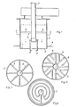
- Fig. 1 im Schnitt die bevorzugte Ausführungsform des Brenners;
- Fig. 2 - 4 im Schnitt längs Linie I/I in Fig. 1 und in Ansicht verschiedene Ausführungsformen der Gasverteilerleitungen;
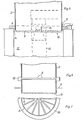
- Fig. 5 im Schnitt eine Ausführungsform des Brenners als abschwenkbare Kesselverschlußtür und
- Fig. 6, 7 eine besondere Ausführungsform bezüglich der Elemente zur Gaszuleitung.
- Figure 1 shows in section the preferred embodiment of the burner.
- Fig. 2-4 in section along line I / I in Figure 1 and in view of various embodiments of the gas distribution lines.
- Fig. 5 in section an embodiment of the burner as a swiveling boiler lock door and
- 6, 7 a special embodiment with respect to the elements for gas supply.
Wie aus Fig. 1 erkennbar, ist an bzw. in der Gas-Luftgemischausströmöffnung 1 des Mischrohres 2 eine gasdurchlässige, den ganzen öffnungsquerschnitt abdeckende Brennermembran 3 angeordnet, die aus einem geeigneten Metallgitter bzw. Metallgewebe besteht. Ferner ist das Mischrohr 2 an seinem Außenumfang mit einem Anschlußflansch 4 versehen und im mittleren Bereich des Mischrohres 2 sind gleichmäßig über den ganzen Mischrohrquerschnitt verteilte und mit Gasausströmöffnungen 5 versehene Gasverteilerleitungen 6 angeordnet, die mit dem Gaszuleitungsrohr 7 verbunden sind und bei diesem Ausführungsbeispiel radial vom Gaszuleitungsrohr 7 abstehen. Aus den genannten Gründen ist der Anschlußflansch 4 am brennermembranseitigen Ende des Mischrohres 2 angesetzt. In Durchströmrichtung ist vorteilhaft vor den Gasverteilerleitungen 6 im Mischrohr ein den Mischrohrquerschnitt entsprechendes Luftverteilerblech 8 bspw. in Form eines Lochbleches angeordnet und entweder am Mischrohr 2 oder an der Gaszufuhrleitung 7 befestigt. Wie angedeutet, kann das Gaszuleitungsrohr auch gleichzeitig als Träger für die Zündelektrode 11 und eine Ionisationselektrode 12 dienen.As can be seen from FIG. 1, on or in the gas-air
Bei relativ kleinem Durchmesser des Mischrohres 2, also bspw. in der Größenordnung von 100 - 150 mm, genügt es, wie in Fig. 2 angedeutet, am Gaszuleitungsrohr 7 radial gleichmäßig verteilt bspw. acht Gasverteilerleitungen in Fogm von kleinen Röhrchen anzuordnen, deren Ausströmöffnung 5 gegen die Brennermembran 3 gerichtet sind. Da eine Durchmesservergrößerung des Mischrohres 2 bspw. in Anpassung an eine entsprechend große Brennkammer zu Bereichen führt, die nicht mehr unmittelbar mit ausströmendem Gas bei nur relativ wenigen Röhrchen beschickt würden, können die Gasverteilerleitungen, wie in Fig. 3 dargestellt, mit Zweigleitungen 6' versehen werden. Eine Ausbildung der Gasverteilerleitungen im Sinne der Fig. 4, also in Form von konzentrischen Ringleitungen, wäre aber ebenfalls möglich.With a relatively small diameter of the
Unter Verweis auf Fig. 6, 7 ist es ferner möglich, auf eine zentrische Anordnung des Gaszufuhrrohres zu verzichten und stattdessen am Außenumfang des Mischrohres 2 die Gaszufuhrleitung in Form eines Ringkanales 10 anzuordnen, an dem dann die Gasverteilerleitungen 6, wie insbesondere aus Fig. 7 erkennbar, in möglichst dichter Besetzung des Gesamtquerschnittes des Mischrohres angesetzt sind.With reference to FIGS. 6, 7, it is also possible to dispense with a central arrangement of the gas supply tube and instead the gas supply on the outer circumference of the
Gemäß Fig. 5 ist das Mischrohr 2 mit seinem Anschlußflansch 4 als schwenkverschließbare Kesselverschlußtür 9 ausgebildet, wobei die Brennermembran 3 in bezug auf die Brennkammer 13 des betreffenden Heizkessels die zuströmseitig gasgekühlte und andererseits insgesamt wärmebelastete Fläche der Kesselverschlußtür 9 bildet. Da, wie erkennbar, lediglich ein.kleiner Ringspalt 14 frei bleibt, können sämtliche sonst erforderlichen Wärmeisolationsmaßnahmen an der Kesselverschlußtür selbst unterbleiben.5, the
Nur zur Verdeutlichung und Gegenüberstellung ist in diesem Ausführungsbeispiel gestrichelt die bisher übliche Ausführungsform derartiger Gas-Gebläsebrenner angedeutet, woraus auch die bisherigen Abmessungen des Mischrohres 15 im Verhältnis zum Durchmesser der Brennkammer 13 deutlich werden.For clarification and comparison only, the previously customary embodiment of such gas forced-air burners is indicated in dashed lines in this exemplary embodiment, from which the previous dimensions of the
Da beim beschriebenen Brenner und wie in Fig. 5 angedeutet, das Gas-Luftgemisch als flächige Flammfront 16 brennt und zwar im Gegensatz zur gebündelten Flamme 17 mit hoher Strömungsgeschwindigkeit und relativ großer Länge, ergibt sich für den mit einem solchen Brenner ausgestatteten Heizkessel auch der Vorteil, daß dessen Brennkammer extrem kurz bemessen werden kann.Since, in the burner described and as indicated in FIG. 5, the gas-air mixture burns as a
Claims (6)
Applications Claiming Priority (2)
| Application Number | Priority Date | Filing Date | Title |
|---|---|---|---|
| DE19853503553 DE3503553A1 (en) | 1985-02-02 | 1985-02-02 | LOW PRESSURE GAS BLOWING BURNER |
| DE3503553 | 1985-02-02 |
Publications (2)
| Publication Number | Publication Date |
|---|---|
| EP0190660A2 true EP0190660A2 (en) | 1986-08-13 |
| EP0190660A3 EP0190660A3 (en) | 1987-10-28 |
Family
ID=6261486
Family Applications (1)
| Application Number | Title | Priority Date | Filing Date |
|---|---|---|---|
| EP86101188A Withdrawn EP0190660A3 (en) | 1985-02-02 | 1986-01-30 | Low compression gas blow burner |
Country Status (2)
| Country | Link |
|---|---|
| EP (1) | EP0190660A3 (en) |
| DE (1) | DE3503553A1 (en) |
Cited By (3)
| Publication number | Priority date | Publication date | Assignee | Title |
|---|---|---|---|---|
| AT388988B (en) * | 1987-01-23 | 1989-09-25 | Vaillant Gmbh | BOILER WITH FAN BURNER FASTENED IN AN OPENING |
| NL1008233C2 (en) * | 1998-02-06 | 1999-08-09 | Clysan D W Bv | Forced injection gas burner for boiler or furnace |
| EP1026445A1 (en) * | 1999-02-08 | 2000-08-09 | D.W. Clysan B.V. | Gas burner |
Families Citing this family (1)
| Publication number | Priority date | Publication date | Assignee | Title |
|---|---|---|---|---|
| DE3861254D1 (en) * | 1987-03-17 | 1991-01-24 | Viessmann Werke Kg | GAS AREA BURNER FOR HEATING BOILERS. |
Citations (8)
| Publication number | Priority date | Publication date | Assignee | Title |
|---|---|---|---|---|
| DE808867C (en) * | 1949-03-25 | 1951-07-19 | Maschf Augsburg Nuernberg Ag | Industrial gas burners |
| FR1574404A (en) * | 1967-07-28 | 1969-07-11 | ||
| FR2209439A5 (en) * | 1972-12-05 | 1974-06-28 | Fritsche Heinrich | |
| US3947233A (en) * | 1971-04-26 | 1976-03-30 | C. A. Sundberg Ab | Free-burning equipment |
| DE2525305A1 (en) * | 1975-06-06 | 1976-12-16 | Pensenskij Kompressornyj Sawod | Gas burner for generating high temperatures - has nozzle with arcuate slots inclined to axis of burner body |
| DE2527073A1 (en) * | 1975-06-18 | 1977-01-13 | Pensenskij Kompressornyj Sawod | High performance burner for gaseous fuels - has radial outlet nozzles for preheated gas and preheated air supply |
| US4082497A (en) * | 1976-03-29 | 1978-04-04 | Ex-Cell-O Corporation | High capacity quiet burner for hot air heating system |
| DE3415946A1 (en) * | 1983-05-19 | 1984-11-22 | Saunier Duval Eau Chaude Chauffage - S.D.E.C.C., Montreuil-sous-Bois | Gas burner with premixing of air and gas |
Family Cites Families (3)
| Publication number | Priority date | Publication date | Assignee | Title |
|---|---|---|---|---|
| AT310996B (en) * | 1970-11-02 | 1973-10-25 | Vaillant Joh Kg | Instantaneous water heater |
| DE2211297A1 (en) * | 1971-04-26 | 1972-11-16 | CA. Sundberg AB, Kallhäll (Schweden) | Gaseous fuel burners |
| DE8025338U1 (en) * | 1980-09-22 | 1984-05-03 | Deutsche Forschungs- und Versuchsanstalt für Luft- und Raumfahrt e.V., 5000 Köln | OIL AND GAS BURNERS FOR INSTALLATION IN HEATING AND STEAM GENERATING BOILERS |
-
1985
- 1985-02-02 DE DE19853503553 patent/DE3503553A1/en active Granted
-
1986
- 1986-01-30 EP EP86101188A patent/EP0190660A3/en not_active Withdrawn
Patent Citations (8)
| Publication number | Priority date | Publication date | Assignee | Title |
|---|---|---|---|---|
| DE808867C (en) * | 1949-03-25 | 1951-07-19 | Maschf Augsburg Nuernberg Ag | Industrial gas burners |
| FR1574404A (en) * | 1967-07-28 | 1969-07-11 | ||
| US3947233A (en) * | 1971-04-26 | 1976-03-30 | C. A. Sundberg Ab | Free-burning equipment |
| FR2209439A5 (en) * | 1972-12-05 | 1974-06-28 | Fritsche Heinrich | |
| DE2525305A1 (en) * | 1975-06-06 | 1976-12-16 | Pensenskij Kompressornyj Sawod | Gas burner for generating high temperatures - has nozzle with arcuate slots inclined to axis of burner body |
| DE2527073A1 (en) * | 1975-06-18 | 1977-01-13 | Pensenskij Kompressornyj Sawod | High performance burner for gaseous fuels - has radial outlet nozzles for preheated gas and preheated air supply |
| US4082497A (en) * | 1976-03-29 | 1978-04-04 | Ex-Cell-O Corporation | High capacity quiet burner for hot air heating system |
| DE3415946A1 (en) * | 1983-05-19 | 1984-11-22 | Saunier Duval Eau Chaude Chauffage - S.D.E.C.C., Montreuil-sous-Bois | Gas burner with premixing of air and gas |
Cited By (3)
| Publication number | Priority date | Publication date | Assignee | Title |
|---|---|---|---|---|
| AT388988B (en) * | 1987-01-23 | 1989-09-25 | Vaillant Gmbh | BOILER WITH FAN BURNER FASTENED IN AN OPENING |
| NL1008233C2 (en) * | 1998-02-06 | 1999-08-09 | Clysan D W Bv | Forced injection gas burner for boiler or furnace |
| EP1026445A1 (en) * | 1999-02-08 | 2000-08-09 | D.W. Clysan B.V. | Gas burner |
Also Published As
| Publication number | Publication date |
|---|---|
| DE3503553C2 (en) | 1987-06-19 |
| DE3503553A1 (en) | 1986-08-07 |
| EP0190660A3 (en) | 1987-10-28 |
Similar Documents
| Publication | Publication Date | Title |
|---|---|---|
| EP0309838B1 (en) | Gasburner | |
| DE2541991C3 (en) | burner | |
| DE1897407U (en) | GAS BURNER. | |
| DE2428622A1 (en) | Nozzle head for burning gas with compressed air - has plate for retarding air flow speed and for mixing gas with air | |
| DE2119831C2 (en) | Gas burner | |
| DE2134330C3 (en) | Device for generating a high-speed flow of hot gas with a gas burner | |
| EP0190660A2 (en) | Low compression gas blow burner | |
| DE3503554C2 (en) | ||
| DE1213960B (en) | Melting and / or holding furnace | |
| DE2700786C3 (en) | Ceramic gas burner for wind heaters | |
| DE2364053C2 (en) | Combustion system | |
| DE2715456A1 (en) | Oil burner oil and air mixer - has central air entry inside swirl plates, outer ring of secondary air holes | |
| EP0601018B1 (en) | Gas burner, in particular for liquefied gas | |
| DE3009764A1 (en) | COAL BURNER | |
| DE3318860C2 (en) | Burners for heating air | |
| EP0209703B1 (en) | Glow insert for furnaces, in particular for boilers, and furnace equipped with such a glow insert | |
| DE3327140A1 (en) | GAS BURNER, ESPECIALLY FOR LIQUID GAS, FOR INSTALLATION IN A HEAT EXCHANGER | |
| DE2242037C2 (en) | Tubular gas burner, especially for dryers | |
| EP0115858A1 (en) | Burner for fitting in heating installations and steam generation plants | |
| DE3024637C2 (en) | Gas stove with a hob formed by a heat transferring plate | |
| DE3131948C2 (en) | ||
| DE3506640A1 (en) | Mixing head for a gasification oil burner | |
| DE2351418C3 (en) | Device for the combustion of variable amounts of exhaust gas | |
| DE2125365C3 (en) | Radiant burners for gaseous fuels | |
| DE2807186A1 (en) | MIXING HEAD FOR BURNERS WITH SMALL HEATING CAPACITY |
Legal Events
| Date | Code | Title | Description |
|---|---|---|---|
| PUAI | Public reference made under article 153(3) epc to a published international application that has entered the european phase |
Free format text: ORIGINAL CODE: 0009012 |
|
| AK | Designated contracting states |
Kind code of ref document: A2 Designated state(s): AT BE CH FR IT LI LU NL SE |
|
| PUAL | Search report despatched |
Free format text: ORIGINAL CODE: 0009013 |
|
| AK | Designated contracting states |
Kind code of ref document: A3 Designated state(s): AT BE CH FR IT LI LU NL SE |
|
| STAA | Information on the status of an ep patent application or granted ep patent |
Free format text: STATUS: THE APPLICATION IS DEEMED TO BE WITHDRAWN |
|
| 18D | Application deemed to be withdrawn |
Effective date: 19880429 |