EP0190556A2 - Agencement pour supprimer le choc de passage de vitesse dans la transmission automatique d'un véhicule - Google Patents
Agencement pour supprimer le choc de passage de vitesse dans la transmission automatique d'un véhicule Download PDFInfo
- Publication number
- EP0190556A2 EP0190556A2 EP86100173A EP86100173A EP0190556A2 EP 0190556 A2 EP0190556 A2 EP 0190556A2 EP 86100173 A EP86100173 A EP 86100173A EP 86100173 A EP86100173 A EP 86100173A EP 0190556 A2 EP0190556 A2 EP 0190556A2
- Authority
- EP
- European Patent Office
- Prior art keywords
- chamber
- transmission
- friction element
- accumulator
- port
- Prior art date
- Legal status (The legal status is an assumption and is not a legal conclusion. Google has not performed a legal analysis and makes no representation as to the accuracy of the status listed.)
- Granted
Links
Images


Classifications
-
- F—MECHANICAL ENGINEERING; LIGHTING; HEATING; WEAPONS; BLASTING
- F16—ENGINEERING ELEMENTS AND UNITS; GENERAL MEASURES FOR PRODUCING AND MAINTAINING EFFECTIVE FUNCTIONING OF MACHINES OR INSTALLATIONS; THERMAL INSULATION IN GENERAL
- F16H—GEARING
- F16H61/00—Control functions within control units of change-speed- or reversing-gearings for conveying rotary motion ; Control of exclusively fluid gearing, friction gearing, gearings with endless flexible members or other particular types of gearing
- F16H61/04—Smoothing ratio shift
- F16H61/06—Smoothing ratio shift by controlling rate of change of fluid pressure
- F16H61/061—Smoothing ratio shift by controlling rate of change of fluid pressure using electric control means
-
- F—MECHANICAL ENGINEERING; LIGHTING; HEATING; WEAPONS; BLASTING
- F16—ENGINEERING ELEMENTS AND UNITS; GENERAL MEASURES FOR PRODUCING AND MAINTAINING EFFECTIVE FUNCTIONING OF MACHINES OR INSTALLATIONS; THERMAL INSULATION IN GENERAL
- F16H—GEARING
- F16H61/00—Control functions within control units of change-speed- or reversing-gearings for conveying rotary motion ; Control of exclusively fluid gearing, friction gearing, gearings with endless flexible members or other particular types of gearing
- F16H61/04—Smoothing ratio shift
- F16H2061/0466—Smoothing shift shock by apply or release of band brake servos, e.g. overlap control of band brake and a clutch or vice versa
-
- F—MECHANICAL ENGINEERING; LIGHTING; HEATING; WEAPONS; BLASTING
- F16—ENGINEERING ELEMENTS AND UNITS; GENERAL MEASURES FOR PRODUCING AND MAINTAINING EFFECTIVE FUNCTIONING OF MACHINES OR INSTALLATIONS; THERMAL INSULATION IN GENERAL
- F16H—GEARING
- F16H59/00—Control inputs to control units of change-speed-, or reversing-gearings for conveying rotary motion
- F16H59/68—Inputs being a function of gearing status
- F16H59/70—Inputs being a function of gearing status dependent on the ratio established
Definitions
- the present invention relates generally to an automatic automotive transmission and more specifically to an arrangement therefor which attenuates shift shock over a wide range of engine load and speed.
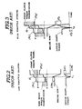
- Fig. 1 shows a portion of a prior art transmission disclosed in detail in SERVICE MANUAL Nissan Automatic Transmission Model 3N71B.
- the disclosure of the above mentioned service manual is hereby incorporated by reference thereto.
- the band brake 2 is arranged to have a servo 4 which includes an apply chamber 6 and a release chamber 8.
- the stepped piston 10 which is disposed between the opposed chambers 6. 8 is arranged so that the surface area exposed to the release chamber 8 is greater than that exposed to the apply chamber 6 so that even if both chambers are applied with pressures of equal magnitude (eg. both chambers are supplied with line pressure) the brake will assume a released condition upon pressurization of the release chamber 8.
- the 2 -3 shift valve 3 includes a spool 12 which when in the downshift position (upper half section) connects port with a drain 16 while in the upshift position (lower half section) connects port 14 with a port is which is supplied with line pressure.
- a spool 12 which when in the downshift position (upper half section) connects port with a drain 16 while in the upshift position (lower half section) connects port 14 with a port is which is supplied with line pressure.
- a flow restricting orifice 2 4 is interposed between port 14 and chambers 8 and 20.
- two orifices are disposed in the conduits at locations indicated schematically by the phantom boxes. However, for simplicity of illustration only one orifice is shown and is illustrated in a position wherein the effect of the above mentioned two is provided.
- Fig. 4 shows a second example of prior art. This arrangement is disclosed in detail in SERVICE MANUAL Nissan Automatic Transmission Model RN 3F 0 1A. This arrangement differs from the one shown in Fig. 1 in that only the communication between port 14 and the release chamber 8 of the band brake 2 is restricted by a flow restriction 26. The reason for this provision is to enable slow the engagement of the band brake 2 with respect to the release of the front clutch 1 in an effort to smooth the shift by enabling the engine to race slightly in a manner which brings the engine speed up to a level which matches that which will result after the shift is completed.
- an accumulator is connected to the fluid circuit via which line pressure is supplied from a 2-3 shift valve in a manner that the enagagement/release of the two friction elements is staged in a manner that reduces sharp fluctuations in the output shaft torque.
- the present invention takes the form of a transmission for an automotive vehicle which is characterized by: a first friction element, the first friction element having a first chamber which when supplied with hydraulic pressure causes the first friction element to assume an engaged condition: a second friction element, the second friction element having a second chamber which when supplied with hydraulic pressure induces the second friction element to assume a released condition: the transmission being arranged so that a first speed ratio is produced when the first and second friction elements are released and engaged respectively, and a second speed ratio when the first and second friction elements are engaged and released respectively; a shift valve, the shift valve having a valve element which establishes communication between a source of hydraulic pressure and a port when in an upshift position and communication between the port and a drain when in a downshift position: a fluid circuit which interconnects the port and the first and second chambers; an accumulator having a third chamber in unrestricted fluid communication with the second chamber: and a flow restrictor fluidly disposed in the fluid circuit between the port and the second chamber.
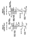
- Fig. 7 shows a first embodiment of the present invention.
- an accumulator 100 is added to an arrangement which is otherwise essentially the same as the arrangement shown in Fig. 1. Accordingly, the same numerals will be used to denote like elements and a redundant description thereof be omitted for brevity.
- the accumulator 100 in this embodiment includes a stepped bore 102 in which a stepped piston 104 is reciprocatively disposed.
- the fluid circuit 106 which interconnects the 2- 3 shift valve with the front clutch 1 and band brake 2 is arranged to communicate with a variable volume chamber 108 via conduit 110.
- the arrangement of the orifice 24 in the circuit 106 is such as to permit unrestricted communication between chamber 108 and chambers 8 and 20.
- a second variable volume chamber 112 is defined in the stepped bore 102.
- This chamber is supplied with a control pressure-for example line pressure (however, it is within the scope of the present invention to utilize a different pressure such as governor presssure, throttle pressure or the like under the instance that such is effective.).
- the effective surface area of the piston exposed to chamber 112 is less that that exposed to chamber 108 so that upon chamber 108 being supplied with line pressure due to the upshifting of the 2-3 shift valve 3 the piston 104 will be driven down against the combined bias of the pressure in chamber 112 and the spring 114 disposed in a third chamber 116 defined in the stepped bore. It will be noted that in this embodiment chamber 116 is drained.
- Fig. 8 shows the shift shock suppressing characteristics when a 2-3 upshift is effected at low throttle opening.
- the upon the upshift line pressure is fed into the fluid circuit 106 via flow restriction 24. This pressure is delivered to chambers 8, 20 and 108. Due to the provision of the accumulator 100 pressure (P C ) develops in a staged manner as shown, which in turn causes the number of stages with which torque transmitted by the forward clutch develops to increase. Viz., an additional stage or level a2 occurs. The release of the band brake is effected in a similar manner.
- the accumulator 100 modifes the pressure development in chambers 8 and 20 in a manner that under these circumstances again the stages in the torque transmission characteristics by the front clutch increases (viz., includes stage a2) while the torque transmission characteristics of the band brake 2 are such as reduce stagewise ( ⁇ 1, ⁇ 2) whereby the momentary partial locking of the tranmission does not take place and the output shaft torque does not fluctuate to the point of becomming negative as in the case of the Fig. 1 prior art.
- the height of the levels a2 and P2 can be varied by changing the design (dimensions etc.) of the accumulator 100.
- Fig. 10 shows a second embodiment of the present invention.
- a one-way flow restriction 120 arrangement is disposed between port 1 4 and the chambers 8 and 20 while a fixed flow restriction 28 is disposed between the one-way flow restriction and the release chamber 8 of the band brake servo 4.
- An accumulator 100 is, in this embodiment, connected to the fluid circuit 106 at a location between the flow restriction 28 and the release chamber 8. With this connection the chamber 1 08 of the accumultor is placed in unrestricted fluid communication with the the release chamber and in restricted communication with chamber 20 of the front clutch servo 22.
- the release pressure (P R ) lowers in a stage-wise manner so that over time tl the pressure in the release chamber lowers as shown by a3 and induces the torque transmitted by the brand brake to increase slowly as shown by p3.
- the pressure (P C ) in chamber 20 lowers over time period ti in manner indicated by a4.
- the torque transmitted by the front clutch reduces as shown by p 4 .
- the engine speed rises desirably as shown, and the output shaft torque curve shows a greatly reduced tendancy to be reduced.
- shift shock is obviated.
Landscapes
- Engineering & Computer Science (AREA)
- General Engineering & Computer Science (AREA)
- Physics & Mathematics (AREA)
- Fluid Mechanics (AREA)
- Mechanical Engineering (AREA)
- Control Of Transmission Device (AREA)
- Gear-Shifting Mechanisms (AREA)
Applications Claiming Priority (4)
| Application Number | Priority Date | Filing Date | Title |
|---|---|---|---|
| JP78785A JPS61160656A (ja) | 1985-01-09 | 1985-01-09 | 自動変速機の変速シヨツク軽減装置 |
| JP787/85 | 1985-01-09 | ||
| JP286685A JPS61165054A (ja) | 1985-01-11 | 1985-01-11 | 自動変速機の変速シヨツク軽減装置 |
| JP2866/85 | 1985-01-11 |
Publications (3)
| Publication Number | Publication Date |
|---|---|
| EP0190556A2 true EP0190556A2 (fr) | 1986-08-13 |
| EP0190556A3 EP0190556A3 (en) | 1987-03-11 |
| EP0190556B1 EP0190556B1 (fr) | 1990-05-09 |
Family
ID=26333861
Family Applications (1)
| Application Number | Title | Priority Date | Filing Date |
|---|---|---|---|
| EP86100173A Expired - Lifetime EP0190556B1 (fr) | 1985-01-09 | 1986-01-08 | Agencement pour supprimer le choc de passage de vitesse dans la transmission automatique d'un véhicule |
Country Status (3)
| Country | Link |
|---|---|
| US (1) | US4729265A (fr) |
| EP (1) | EP0190556B1 (fr) |
| DE (1) | DE3671083D1 (fr) |
Cited By (2)
| Publication number | Priority date | Publication date | Assignee | Title |
|---|---|---|---|---|
| EP0314193A2 (fr) * | 1987-10-30 | 1989-05-03 | Nissan Motor Co., Ltd. | Arrangement d'accumulateur dans le circuit de commande d'une transmission automatique |
| EP0314191A2 (fr) * | 1987-10-30 | 1989-05-03 | Nissan Motor Co., Ltd. | Arrangement d'accumulateur/élément de friction pour une transmission automatique |
Families Citing this family (11)
| Publication number | Priority date | Publication date | Assignee | Title |
|---|---|---|---|---|
| JPS63140150A (ja) * | 1986-11-18 | 1988-06-11 | フオルクスヴアーゲン・アクチエンゲゼルシヤフト | 液圧的な制御装置 |
| US4930080A (en) * | 1987-05-15 | 1990-05-29 | Nissan Motor Co., Ltd. | Control arrangement for automatic transmission |
| US4928557A (en) * | 1987-12-04 | 1990-05-29 | Toyota Jidosha Kabushiki Kaisha | Hydraulic transmission controller with coupling pressure compensation |
| DE68920226T2 (de) * | 1988-08-02 | 1995-05-11 | Toyota Motor Co Ltd | Akkumulatorsteuerung mit motorleistungsabhängigem Gegendruck für die hydraulische Steuerung eines automatischen Fahrzeuggetriebes. |
| JP2592129B2 (ja) * | 1989-04-27 | 1997-03-19 | 日産自動車株式会社 | 自動変速機の液圧制御装置 |
| JP3103568B2 (ja) * | 1989-06-29 | 2000-10-30 | アイシン・エィ・ダブリュ株式会社 | 自動変速機における油圧制御装置 |
| JP2646863B2 (ja) * | 1991-01-29 | 1997-08-27 | 日産自動車株式会社 | 変速機の油圧制御装置 |
| JP2952722B2 (ja) * | 1991-04-05 | 1999-09-27 | アイシン精機株式会社 | 自動変速機の油圧制御装置 |
| US5311795A (en) * | 1991-06-17 | 1994-05-17 | Mazda Motor Corporation | Control system with band brake actuator for automatic transmission |
| US5536221A (en) * | 1994-08-16 | 1996-07-16 | Deltrans, Inc. | Retrofit means for adjusting shift timing in an existing automatic transmission |
| JP3364739B2 (ja) * | 1996-12-19 | 2003-01-08 | ジヤトコ株式会社 | 自動変速機のアップシフト制御装置 |
Citations (7)
| Publication number | Priority date | Publication date | Assignee | Title |
|---|---|---|---|---|
| US3623382A (en) * | 1970-02-17 | 1971-11-30 | Gen Motors Corp | Transmission control |
| DE2137160A1 (de) * | 1971-07-24 | 1973-02-01 | Volkswagenwerk Ag | Hydraulische steuervorrichtung zum selbsttaetigen umschalten eines umlaufgetriebes, insbesondere fuer kraftfahrzeuge |
| GB2028937A (en) * | 1978-08-07 | 1980-03-12 | Nissan Motor | Shock Control Arrangement in Hydraulic Control System of Automatic Power Transmission |
| GB2031533A (en) * | 1978-08-07 | 1980-04-23 | Nissan Motor | Shift shock reducing device |
| GB2061422A (en) * | 1979-10-15 | 1981-05-13 | Nissan Motor | Gear shift shock reducing apparatus for hydraulic control system of automatic transmission |
| GB2072772A (en) * | 1980-03-27 | 1981-10-07 | Toyota Motor Co Ltd | Transmission control system with back pressure accumulator |
| GB2147669A (en) * | 1983-10-07 | 1985-05-15 | Nissan Motor | Lock-up control for torque converter of automatic transmission |
Family Cites Families (8)
| Publication number | Priority date | Publication date | Assignee | Title |
|---|---|---|---|---|
| US3733927A (en) * | 1971-10-26 | 1973-05-22 | Toyota Motor Co Ltd | Hydraulic control system for an automatic transmission |
| US3842693A (en) * | 1972-07-29 | 1974-10-22 | Volkswagenwerk Ag | Hydraulic control device for controlling downshift of automatic transmission |
| JPS5829420B2 (ja) * | 1976-09-13 | 1983-06-22 | トヨタ自動車株式会社 | 自動変速機の油圧制御装置 |
| JPS5922098B2 (ja) * | 1976-12-09 | 1984-05-24 | 三菱自動車工業株式会社 | 油圧式自動変速機の変速装置 |
| JPS5948902B2 (ja) * | 1978-08-30 | 1984-11-29 | 日産自動車株式会社 | 自動変速機のシヨツク軽減装置 |
| US4274308A (en) * | 1978-11-06 | 1981-06-23 | Nissan Motor Company, Limited | Shock control arrangement in hydraulic control system |
| JPS57144338A (en) * | 1981-02-26 | 1982-09-06 | Nissan Motor Co Ltd | Shifter for automatic gear change |
| JPS59155649A (ja) * | 1983-02-21 | 1984-09-04 | Nissan Motor Co Ltd | 自動変速機の油圧制御装置 |
-
1986
- 1986-01-03 US US06/816,154 patent/US4729265A/en not_active Expired - Lifetime
- 1986-01-08 EP EP86100173A patent/EP0190556B1/fr not_active Expired - Lifetime
- 1986-01-08 DE DE8686100173T patent/DE3671083D1/de not_active Expired - Lifetime
Patent Citations (7)
| Publication number | Priority date | Publication date | Assignee | Title |
|---|---|---|---|---|
| US3623382A (en) * | 1970-02-17 | 1971-11-30 | Gen Motors Corp | Transmission control |
| DE2137160A1 (de) * | 1971-07-24 | 1973-02-01 | Volkswagenwerk Ag | Hydraulische steuervorrichtung zum selbsttaetigen umschalten eines umlaufgetriebes, insbesondere fuer kraftfahrzeuge |
| GB2028937A (en) * | 1978-08-07 | 1980-03-12 | Nissan Motor | Shock Control Arrangement in Hydraulic Control System of Automatic Power Transmission |
| GB2031533A (en) * | 1978-08-07 | 1980-04-23 | Nissan Motor | Shift shock reducing device |
| GB2061422A (en) * | 1979-10-15 | 1981-05-13 | Nissan Motor | Gear shift shock reducing apparatus for hydraulic control system of automatic transmission |
| GB2072772A (en) * | 1980-03-27 | 1981-10-07 | Toyota Motor Co Ltd | Transmission control system with back pressure accumulator |
| GB2147669A (en) * | 1983-10-07 | 1985-05-15 | Nissan Motor | Lock-up control for torque converter of automatic transmission |
Cited By (5)
| Publication number | Priority date | Publication date | Assignee | Title |
|---|---|---|---|---|
| EP0314193A2 (fr) * | 1987-10-30 | 1989-05-03 | Nissan Motor Co., Ltd. | Arrangement d'accumulateur dans le circuit de commande d'une transmission automatique |
| EP0314191A2 (fr) * | 1987-10-30 | 1989-05-03 | Nissan Motor Co., Ltd. | Arrangement d'accumulateur/élément de friction pour une transmission automatique |
| EP0314193A3 (en) * | 1987-10-30 | 1990-06-27 | Nissan Motor Co., Ltd. | Accumulator arrangement for automatic transmission control circuit |
| US5038637A (en) * | 1987-10-30 | 1991-08-13 | Nissan Motor Co., Ltd. | Accumulator arrangement for automatic transmission control circuit |
| EP0314191B1 (fr) * | 1987-10-30 | 1994-06-15 | Nissan Motor Co., Ltd. | Arrangement d'accumulateur/élément de friction pour une transmission automatique |
Also Published As
| Publication number | Publication date |
|---|---|
| DE3671083D1 (de) | 1990-06-13 |
| EP0190556B1 (fr) | 1990-05-09 |
| US4729265A (en) | 1988-03-08 |
| EP0190556A3 (en) | 1987-03-11 |
Similar Documents
| Publication | Publication Date | Title |
|---|---|---|
| US4095486A (en) | Device for controlling a lock-up clutch in an automatic transmission | |
| US4729265A (en) | Shift shock suppression arrangement for automotive automatic transmission | |
| CA1121182A (fr) | Systeme hydraulique de commande pour train d'engrenages planetaires, particulierement pour vehicules automobiles | |
| US3688608A (en) | Transmission control mechanism | |
| US4143563A (en) | Hydraulic control system for use in automatic transmission | |
| EP0627580B1 (fr) | Système de commande à changement de vitesses pour une transmission automatique | |
| US4219109A (en) | Oil pressure control means for an automatic transmission | |
| US3927579A (en) | Down shift inhibitor system for automatic transmission control | |
| US3818783A (en) | Manual and automatic shift controls for transmissions | |
| US4108022A (en) | Device for controlling the speed shift operation of an automatic transmission | |
| US4431096A (en) | Direct-coupling clutch control system for an automatic transmission | |
| GB1251534A (fr) | ||
| US4882952A (en) | Hydraulic control system for automatic transmission with shifting shock reducing means | |
| GB2033033A (en) | Shift points control apparatus for an automatic transmission | |
| GB1196720A (en) | Hydraulic Control System for Automatic Transmission | |
| US4660693A (en) | Hydraulic pressure control apparatus for use in automatic transmission | |
| GB1588003A (en) | Multi-ratio transmissions | |
| EP0314193B1 (fr) | Arrangement d'accumulateur dans le circuit de commande d'une transmission automatique | |
| GB1123081A (en) | Motor vehicle automatic change-speed transmission | |
| US4200008A (en) | Hydraulic actuating system for a pair of concurrently operating friction devices for the selection of speeds of a load-shiftable transmission | |
| EP0314191B1 (fr) | Arrangement d'accumulateur/élément de friction pour une transmission automatique | |
| US4706523A (en) | Automatic transmission with upshift smoothing valve | |
| US4616532A (en) | Automatic transmission hydraulic pressure control system with one-way fluid drain passage bypassing downshift timing subsystem | |
| US4065985A (en) | Oil pressure control system for an automatic transmission system | |
| US3330170A (en) | Transmission |
Legal Events
| Date | Code | Title | Description |
|---|---|---|---|
| PUAI | Public reference made under article 153(3) epc to a published international application that has entered the european phase |
Free format text: ORIGINAL CODE: 0009012 |
|
| 17P | Request for examination filed |
Effective date: 19860108 |
|
| AK | Designated contracting states |
Kind code of ref document: A2 Designated state(s): DE FR GB |
|
| PUAL | Search report despatched |
Free format text: ORIGINAL CODE: 0009013 |
|
| AK | Designated contracting states |
Kind code of ref document: A3 Designated state(s): DE FR GB |
|
| 17Q | First examination report despatched |
Effective date: 19880429 |
|
| GRAA | (expected) grant |
Free format text: ORIGINAL CODE: 0009210 |
|
| AK | Designated contracting states |
Kind code of ref document: B1 Designated state(s): DE FR GB |
|
| REF | Corresponds to: |
Ref document number: 3671083 Country of ref document: DE Date of ref document: 19900613 |
|
| ET | Fr: translation filed | ||
| PLBE | No opposition filed within time limit |
Free format text: ORIGINAL CODE: 0009261 |
|
| STAA | Information on the status of an ep patent application or granted ep patent |
Free format text: STATUS: NO OPPOSITION FILED WITHIN TIME LIMIT |
|
| 26N | No opposition filed | ||
| REG | Reference to a national code |
Ref country code: GB Ref legal event code: IF02 |
|
| PGFP | Annual fee paid to national office [announced via postgrant information from national office to epo] |
Ref country code: GB Payment date: 20050105 Year of fee payment: 20 |
|
| PGFP | Annual fee paid to national office [announced via postgrant information from national office to epo] |
Ref country code: DE Payment date: 20050106 Year of fee payment: 20 |
|
| PGFP | Annual fee paid to national office [announced via postgrant information from national office to epo] |
Ref country code: FR Payment date: 20050110 Year of fee payment: 20 |
|
| PG25 | Lapsed in a contracting state [announced via postgrant information from national office to epo] |
Ref country code: GB Free format text: LAPSE BECAUSE OF EXPIRATION OF PROTECTION Effective date: 20060107 |
|
| REG | Reference to a national code |
Ref country code: GB Ref legal event code: PE20 |