EP0190431A2 - Hydraulic system - Google Patents
Hydraulic system Download PDFInfo
- Publication number
- EP0190431A2 EP0190431A2 EP85115425A EP85115425A EP0190431A2 EP 0190431 A2 EP0190431 A2 EP 0190431A2 EP 85115425 A EP85115425 A EP 85115425A EP 85115425 A EP85115425 A EP 85115425A EP 0190431 A2 EP0190431 A2 EP 0190431A2
- Authority
- EP
- European Patent Office
- Prior art keywords
- pressure
- consumer
- valve
- line
- assigned
- Prior art date
- Legal status (The legal status is an assumption and is not a legal conclusion. Google has not performed a legal analysis and makes no representation as to the accuracy of the status listed.)
- Granted
Links
Images
Classifications
-
- E—FIXED CONSTRUCTIONS
- E02—HYDRAULIC ENGINEERING; FOUNDATIONS; SOIL SHIFTING
- E02F—DREDGING; SOIL-SHIFTING
- E02F9/00—Component parts of dredgers or soil-shifting machines, not restricted to one of the kinds covered by groups E02F3/00 - E02F7/00
- E02F9/20—Drives; Control devices
- E02F9/22—Hydraulic or pneumatic drives
- E02F9/2278—Hydraulic circuits
- E02F9/2292—Systems with two or more pumps
-
- E—FIXED CONSTRUCTIONS
- E02—HYDRAULIC ENGINEERING; FOUNDATIONS; SOIL SHIFTING
- E02F—DREDGING; SOIL-SHIFTING
- E02F9/00—Component parts of dredgers or soil-shifting machines, not restricted to one of the kinds covered by groups E02F3/00 - E02F7/00
- E02F9/20—Drives; Control devices
- E02F9/22—Hydraulic or pneumatic drives
- E02F9/2221—Control of flow rate; Load sensing arrangements
- E02F9/2239—Control of flow rate; Load sensing arrangements using two or more pumps with cross-assistance
-
- F—MECHANICAL ENGINEERING; LIGHTING; HEATING; WEAPONS; BLASTING
- F15—FLUID-PRESSURE ACTUATORS; HYDRAULICS OR PNEUMATICS IN GENERAL
- F15B—SYSTEMS ACTING BY MEANS OF FLUIDS IN GENERAL; FLUID-PRESSURE ACTUATORS, e.g. SERVOMOTORS; DETAILS OF FLUID-PRESSURE SYSTEMS, NOT OTHERWISE PROVIDED FOR
- F15B11/00—Servomotor systems without provision for follow-up action; Circuits therefor
- F15B11/16—Servomotor systems without provision for follow-up action; Circuits therefor with two or more servomotors
- F15B11/161—Servomotor systems without provision for follow-up action; Circuits therefor with two or more servomotors with sensing of servomotor demand or load
- F15B11/162—Servomotor systems without provision for follow-up action; Circuits therefor with two or more servomotors with sensing of servomotor demand or load for giving priority to particular servomotors or users
-
- F—MECHANICAL ENGINEERING; LIGHTING; HEATING; WEAPONS; BLASTING
- F15—FLUID-PRESSURE ACTUATORS; HYDRAULICS OR PNEUMATICS IN GENERAL
- F15B—SYSTEMS ACTING BY MEANS OF FLUIDS IN GENERAL; FLUID-PRESSURE ACTUATORS, e.g. SERVOMOTORS; DETAILS OF FLUID-PRESSURE SYSTEMS, NOT OTHERWISE PROVIDED FOR
- F15B11/00—Servomotor systems without provision for follow-up action; Circuits therefor
- F15B11/16—Servomotor systems without provision for follow-up action; Circuits therefor with two or more servomotors
- F15B11/161—Servomotor systems without provision for follow-up action; Circuits therefor with two or more servomotors with sensing of servomotor demand or load
- F15B11/165—Servomotor systems without provision for follow-up action; Circuits therefor with two or more servomotors with sensing of servomotor demand or load for adjusting the pump output or bypass in response to demand
-
- F—MECHANICAL ENGINEERING; LIGHTING; HEATING; WEAPONS; BLASTING
- F15—FLUID-PRESSURE ACTUATORS; HYDRAULICS OR PNEUMATICS IN GENERAL
- F15B—SYSTEMS ACTING BY MEANS OF FLUIDS IN GENERAL; FLUID-PRESSURE ACTUATORS, e.g. SERVOMOTORS; DETAILS OF FLUID-PRESSURE SYSTEMS, NOT OTHERWISE PROVIDED FOR
- F15B11/00—Servomotor systems without provision for follow-up action; Circuits therefor
- F15B11/16—Servomotor systems without provision for follow-up action; Circuits therefor with two or more servomotors
- F15B11/17—Servomotor systems without provision for follow-up action; Circuits therefor with two or more servomotors using two or more pumps
-
- F—MECHANICAL ENGINEERING; LIGHTING; HEATING; WEAPONS; BLASTING
- F15—FLUID-PRESSURE ACTUATORS; HYDRAULICS OR PNEUMATICS IN GENERAL
- F15B—SYSTEMS ACTING BY MEANS OF FLUIDS IN GENERAL; FLUID-PRESSURE ACTUATORS, e.g. SERVOMOTORS; DETAILS OF FLUID-PRESSURE SYSTEMS, NOT OTHERWISE PROVIDED FOR
- F15B2211/00—Circuits for servomotor systems
- F15B2211/20—Fluid pressure source, e.g. accumulator or variable axial piston pump
- F15B2211/205—Systems with pumps
- F15B2211/2053—Type of pump
- F15B2211/20538—Type of pump constant capacity
-
- F—MECHANICAL ENGINEERING; LIGHTING; HEATING; WEAPONS; BLASTING
- F15—FLUID-PRESSURE ACTUATORS; HYDRAULICS OR PNEUMATICS IN GENERAL
- F15B—SYSTEMS ACTING BY MEANS OF FLUIDS IN GENERAL; FLUID-PRESSURE ACTUATORS, e.g. SERVOMOTORS; DETAILS OF FLUID-PRESSURE SYSTEMS, NOT OTHERWISE PROVIDED FOR
- F15B2211/00—Circuits for servomotor systems
- F15B2211/20—Fluid pressure source, e.g. accumulator or variable axial piston pump
- F15B2211/205—Systems with pumps
- F15B2211/20576—Systems with pumps with multiple pumps
-
- F—MECHANICAL ENGINEERING; LIGHTING; HEATING; WEAPONS; BLASTING
- F15—FLUID-PRESSURE ACTUATORS; HYDRAULICS OR PNEUMATICS IN GENERAL
- F15B—SYSTEMS ACTING BY MEANS OF FLUIDS IN GENERAL; FLUID-PRESSURE ACTUATORS, e.g. SERVOMOTORS; DETAILS OF FLUID-PRESSURE SYSTEMS, NOT OTHERWISE PROVIDED FOR
- F15B2211/00—Circuits for servomotor systems
- F15B2211/30—Directional control
- F15B2211/305—Directional control characterised by the type of valves
- F15B2211/30505—Non-return valves, i.e. check valves
-
- F—MECHANICAL ENGINEERING; LIGHTING; HEATING; WEAPONS; BLASTING
- F15—FLUID-PRESSURE ACTUATORS; HYDRAULICS OR PNEUMATICS IN GENERAL
- F15B—SYSTEMS ACTING BY MEANS OF FLUIDS IN GENERAL; FLUID-PRESSURE ACTUATORS, e.g. SERVOMOTORS; DETAILS OF FLUID-PRESSURE SYSTEMS, NOT OTHERWISE PROVIDED FOR
- F15B2211/00—Circuits for servomotor systems
- F15B2211/30—Directional control
- F15B2211/305—Directional control characterised by the type of valves
- F15B2211/30525—Directional control valves, e.g. 4/3-directional control valve
-
- F—MECHANICAL ENGINEERING; LIGHTING; HEATING; WEAPONS; BLASTING
- F15—FLUID-PRESSURE ACTUATORS; HYDRAULICS OR PNEUMATICS IN GENERAL
- F15B—SYSTEMS ACTING BY MEANS OF FLUIDS IN GENERAL; FLUID-PRESSURE ACTUATORS, e.g. SERVOMOTORS; DETAILS OF FLUID-PRESSURE SYSTEMS, NOT OTHERWISE PROVIDED FOR
- F15B2211/00—Circuits for servomotor systems
- F15B2211/30—Directional control
- F15B2211/31—Directional control characterised by the positions of the valve element
- F15B2211/3105—Neutral or centre positions
- F15B2211/3111—Neutral or centre positions the pump port being closed in the centre position, e.g. so-called closed centre
-
- F—MECHANICAL ENGINEERING; LIGHTING; HEATING; WEAPONS; BLASTING
- F15—FLUID-PRESSURE ACTUATORS; HYDRAULICS OR PNEUMATICS IN GENERAL
- F15B—SYSTEMS ACTING BY MEANS OF FLUIDS IN GENERAL; FLUID-PRESSURE ACTUATORS, e.g. SERVOMOTORS; DETAILS OF FLUID-PRESSURE SYSTEMS, NOT OTHERWISE PROVIDED FOR
- F15B2211/00—Circuits for servomotor systems
- F15B2211/30—Directional control
- F15B2211/31—Directional control characterised by the positions of the valve element
- F15B2211/3144—Directional control characterised by the positions of the valve element the positions being continuously variable, e.g. as realised by proportional valves
-
- F—MECHANICAL ENGINEERING; LIGHTING; HEATING; WEAPONS; BLASTING
- F15—FLUID-PRESSURE ACTUATORS; HYDRAULICS OR PNEUMATICS IN GENERAL
- F15B—SYSTEMS ACTING BY MEANS OF FLUIDS IN GENERAL; FLUID-PRESSURE ACTUATORS, e.g. SERVOMOTORS; DETAILS OF FLUID-PRESSURE SYSTEMS, NOT OTHERWISE PROVIDED FOR
- F15B2211/00—Circuits for servomotor systems
- F15B2211/30—Directional control
- F15B2211/315—Directional control characterised by the connections of the valve or valves in the circuit
- F15B2211/3157—Directional control characterised by the connections of the valve or valves in the circuit being connected to a pressure source, an output member and a return line
- F15B2211/31576—Directional control characterised by the connections of the valve or valves in the circuit being connected to a pressure source, an output member and a return line having a single pressure source and a single output member
-
- F—MECHANICAL ENGINEERING; LIGHTING; HEATING; WEAPONS; BLASTING
- F15—FLUID-PRESSURE ACTUATORS; HYDRAULICS OR PNEUMATICS IN GENERAL
- F15B—SYSTEMS ACTING BY MEANS OF FLUIDS IN GENERAL; FLUID-PRESSURE ACTUATORS, e.g. SERVOMOTORS; DETAILS OF FLUID-PRESSURE SYSTEMS, NOT OTHERWISE PROVIDED FOR
- F15B2211/00—Circuits for servomotor systems
- F15B2211/30—Directional control
- F15B2211/32—Directional control characterised by the type of actuation
- F15B2211/329—Directional control characterised by the type of actuation actuated by fluid pressure
-
- F—MECHANICAL ENGINEERING; LIGHTING; HEATING; WEAPONS; BLASTING
- F15—FLUID-PRESSURE ACTUATORS; HYDRAULICS OR PNEUMATICS IN GENERAL
- F15B—SYSTEMS ACTING BY MEANS OF FLUIDS IN GENERAL; FLUID-PRESSURE ACTUATORS, e.g. SERVOMOTORS; DETAILS OF FLUID-PRESSURE SYSTEMS, NOT OTHERWISE PROVIDED FOR
- F15B2211/00—Circuits for servomotor systems
- F15B2211/30—Directional control
- F15B2211/35—Directional control combined with flow control
- F15B2211/351—Flow control by regulating means in feed line, i.e. meter-in control
-
- F—MECHANICAL ENGINEERING; LIGHTING; HEATING; WEAPONS; BLASTING
- F15—FLUID-PRESSURE ACTUATORS; HYDRAULICS OR PNEUMATICS IN GENERAL
- F15B—SYSTEMS ACTING BY MEANS OF FLUIDS IN GENERAL; FLUID-PRESSURE ACTUATORS, e.g. SERVOMOTORS; DETAILS OF FLUID-PRESSURE SYSTEMS, NOT OTHERWISE PROVIDED FOR
- F15B2211/00—Circuits for servomotor systems
- F15B2211/40—Flow control
- F15B2211/405—Flow control characterised by the type of flow control means or valve
- F15B2211/40515—Flow control characterised by the type of flow control means or valve with variable throttles or orifices
-
- F—MECHANICAL ENGINEERING; LIGHTING; HEATING; WEAPONS; BLASTING
- F15—FLUID-PRESSURE ACTUATORS; HYDRAULICS OR PNEUMATICS IN GENERAL
- F15B—SYSTEMS ACTING BY MEANS OF FLUIDS IN GENERAL; FLUID-PRESSURE ACTUATORS, e.g. SERVOMOTORS; DETAILS OF FLUID-PRESSURE SYSTEMS, NOT OTHERWISE PROVIDED FOR
- F15B2211/00—Circuits for servomotor systems
- F15B2211/40—Flow control
- F15B2211/415—Flow control characterised by the connections of the flow control means in the circuit
- F15B2211/41563—Flow control characterised by the connections of the flow control means in the circuit being connected to a pressure source and a return line
-
- F—MECHANICAL ENGINEERING; LIGHTING; HEATING; WEAPONS; BLASTING
- F15—FLUID-PRESSURE ACTUATORS; HYDRAULICS OR PNEUMATICS IN GENERAL
- F15B—SYSTEMS ACTING BY MEANS OF FLUIDS IN GENERAL; FLUID-PRESSURE ACTUATORS, e.g. SERVOMOTORS; DETAILS OF FLUID-PRESSURE SYSTEMS, NOT OTHERWISE PROVIDED FOR
- F15B2211/00—Circuits for servomotor systems
- F15B2211/40—Flow control
- F15B2211/42—Flow control characterised by the type of actuation
- F15B2211/428—Flow control characterised by the type of actuation actuated by fluid pressure
-
- F—MECHANICAL ENGINEERING; LIGHTING; HEATING; WEAPONS; BLASTING
- F15—FLUID-PRESSURE ACTUATORS; HYDRAULICS OR PNEUMATICS IN GENERAL
- F15B—SYSTEMS ACTING BY MEANS OF FLUIDS IN GENERAL; FLUID-PRESSURE ACTUATORS, e.g. SERVOMOTORS; DETAILS OF FLUID-PRESSURE SYSTEMS, NOT OTHERWISE PROVIDED FOR
- F15B2211/00—Circuits for servomotor systems
- F15B2211/40—Flow control
- F15B2211/45—Control of bleed-off flow, e.g. control of bypass flow to the return line
-
- F—MECHANICAL ENGINEERING; LIGHTING; HEATING; WEAPONS; BLASTING
- F15—FLUID-PRESSURE ACTUATORS; HYDRAULICS OR PNEUMATICS IN GENERAL
- F15B—SYSTEMS ACTING BY MEANS OF FLUIDS IN GENERAL; FLUID-PRESSURE ACTUATORS, e.g. SERVOMOTORS; DETAILS OF FLUID-PRESSURE SYSTEMS, NOT OTHERWISE PROVIDED FOR
- F15B2211/00—Circuits for servomotor systems
- F15B2211/60—Circuit components or control therefor
- F15B2211/605—Load sensing circuits
- F15B2211/6051—Load sensing circuits having valve means between output member and the load sensing circuit
- F15B2211/6054—Load sensing circuits having valve means between output member and the load sensing circuit using shuttle valves
-
- F—MECHANICAL ENGINEERING; LIGHTING; HEATING; WEAPONS; BLASTING
- F15—FLUID-PRESSURE ACTUATORS; HYDRAULICS OR PNEUMATICS IN GENERAL
- F15B—SYSTEMS ACTING BY MEANS OF FLUIDS IN GENERAL; FLUID-PRESSURE ACTUATORS, e.g. SERVOMOTORS; DETAILS OF FLUID-PRESSURE SYSTEMS, NOT OTHERWISE PROVIDED FOR
- F15B2211/00—Circuits for servomotor systems
- F15B2211/70—Output members, e.g. hydraulic motors or cylinders or control therefor
- F15B2211/71—Multiple output members, e.g. multiple hydraulic motors or cylinders
Definitions
- the invention is based on a hydraulic system according to the preamble of the main claim.
- a hydraulic system according to the preamble of the main claim.
- pressure medium flows eg forklift trucks
- the flow rate of the pump must be adapted to the consumer that is switched on.
- variable displacement pumps are often used, which are automatically adapted to the required pressure medium flow by their regulator, while expensive additional devices are necessary in the case of constant displacement pumps.
- the hydraulic system according to the invention with the characterizing features of the main claim has the advantage that the flow rate adjustment is carried out with the help of constant pumps, in a relatively simple manner and with little equipment.
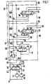
- FIG. 1 shows a hydraulic system in a schematic representation
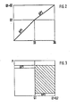
- FIGS. 2 and 3 each show a diagram.
- 10 denotes a first constant pump and 11 a second constant pump, which draw in pressure medium from a container 12.
- the constant pump 10 delivers the pressure medium into a delivery line 13 which leads to a first pressure compensator 14.
- the second constant pump 11 pumps pressure medium into a delivery line 15, which leads to a second pressure compensator 16.
- a line 17 branches off from the delivery line 13 and leads through two blocks 18, 19 and ends at an end plate 20.
- a line 22 branches off from line 17 and leads to a first 5/3-way valve 23 arranged in block 18.
- a check valve 24 which opens in the direction of the directional control valve 23 is arranged in the line 22. From the directional valve 23, two lines 25, 26 lead to a double-acting working cylinder, not shown.
- a line 28 continues from the directional control valve 23 to an alternating check valve 29 of a known type. This is connected to a control line which has four sections 30A to 30D and which extends from the end plate 20.
- the uppermost control line section 30A is connected to a return line 31, into which a line 32 starting from the directional control valve 23 also opens.
- a measuring orifice 33 is formed, which is effective in the working positions I and III, while the position II represents the blocking position.
- block 19 there is a 5/3-way valve 34 which corresponds exactly to the directional control valve 23, of which only the measuring orifice 36 is described in more detail.
- the lines emanating from the directional control valve 34 or those terminating at it are also not designated, since they also correspond to those in block 18. Only the alternate check valve 35 is still designated, which is connected to the control line section 30A.
- the pressure compensator 14 is supplied with the delivery pressure of the constant pump 10 from one end side via a line 37 starting from line 17, and from its other end side via a line 38 connected to the control line section 30C. In section 30C there is a throttle in front of the branch point 39 arranged. A control spring 40 also acts on the pressure compensator 14 from this end face. A line 42 leads from the pressure compensator 14 to the return line 31.
- the pressure compensator 14 has a flow position I and a blocking position II, the transition between the two switching positions being fluid.
- the pressure compensator 16 is acted upon from its one end side via a line 43 connected to the line J3, from its opposite side via the control line section 30D and is additionally loaded by a control spring 44.
- a line 45 leads from the pressure compensator to the return line 31 and on the other hand a line 46 with a built-in check valve 47 to the delivery line 13, the check valve being able to open in the direction from the pressure compensator 16 to the delivery line 13.
- the pressure compensator 16 has two switch positions I and II.
- a pressure relief valve 46 is also connected to the control line section 30C and serves to protect the system.
- the constant pumps 10 and 11 can either be of the same size or they can also provide different delivery rates. In the case specifically described, both are of the same size and are driven by a common drive machine, not shown.
- the preload of the control spring 40 on the pressure compensator 14 is greater than that of the control spring 44 on the pressure compensator 16.
- the alternating check valves 29 and 35 have the purpose of supplying the higher pressure from the consumer connected to the directional control valves 23, 34 into the control line 30A to 30B direct, which is effective on the pressure compensators 14, 16 and the pressure relief valve 46; such valves are also referred to as selector valves.
- the pressure relief valve 46 also serves as a pilot valve for the pressure compensators 14, 16; the throttle 39 is in front of the pressure compensators.
- the two constant pumps 10 and 11 deliver pressure medium and, for example, the directional control valve 23 is switched to switch position I
- pressure medium flows via the delivery line 13, the directional control valve 23 and the line 25 to the consumer.
- the measuring orifice 33 is effective, at which a certain pressure drop ⁇ P1 arises.
- the pressure in the delivery line acts both on the pressure compensator 14 and on the pressure compensator 16.
- the pressure at the consumer is transferred in switch position I via the conduit 28 and the alternating check valve 29 into the control line section 30C, from where it likewise acts on the pressure compensators 14, 16 acts.
- the pressure compensator 16 is in switch position II, so that the quantity of pressure medium delivered by the pump 11 via the line 45 and the return line 34 is immediately in the container 12 flows back.
- the pressure compensator 14 is in the regulating position or, owing to the greater prestress of the spring 40 in locking position II, so that the pressure medium delivered by the pump 30 can flow to the consumer.
- the pressure in the delivery line 13 also drops, whereupon the pressure compensator 16 is gradually controlled into its switching position I. Now the pressure medium delivered by the constant pump 11 can also flow into the delivery line 13 or the line 17 via the line 46 and the check valve 47.
- the consumer connected to the directional control valve 34 can also be supplied with pressure medium at any time. If the higher delivery pressure prevails there than at the other consumer, this pressure is now transferred via the alternating check valve 35 into the control line 30B, 30C, 30D and the valve 22 is closed.
- the diagram according to FIG. 2 shows the openings of the measuring orifices 33, 36 on the abscissa, and the flow rates Q1 and Q2 of the pumps 10, 11 on the ordinate.
- ⁇ P1 results in a flow rate up to Q1
- ⁇ P2 a flow rate up to Q1 + Q2, d. H.
- the pump 10 is switched on the pump 11.
- the orifice 36 is larger than the orifice 33.
- the second diagram shows the power balance when the smaller consumer is operating solo, the second pump 11 remaining at a low neutral circulation pressure.
- the hatched area corresponds to the performance saving compared to a system with only one large pump.
- the order in which the pumps are switched on depends solely on the spring preload of the pressure compensator assigned to each pump.
Landscapes
- Engineering & Computer Science (AREA)
- General Engineering & Computer Science (AREA)
- Physics & Mathematics (AREA)
- Fluid Mechanics (AREA)
- Mechanical Engineering (AREA)
- Mining & Mineral Resources (AREA)
- Civil Engineering (AREA)
- Structural Engineering (AREA)
- Fluid-Pressure Circuits (AREA)
Abstract
Description
Die Erfindung geht aus von einer Hydraulikanlage nach der Gattung des Hauptanspruchs. Bei derartigen bekannten Hydraulikanlagen mit unterschiedlich hohen Verbraucher - Druckmittelströmen (z. B. Gabelstapler) - ist zur Vermeidung von Überhitzung des Druckmittels der Förderstrom der Pumpe dem jeweils eingeschalteten Verbraucher anzupassen. Für solche Anlagen werden häufig Verstellpumpen verwendet, die durch ihren Regler automatisch an den benötigten Druckmittelstrom angepaßt werden, während bei Konstantpumpen teure Zusatzeinrichtungen notwendig sind.The invention is based on a hydraulic system according to the preamble of the main claim. In such known hydraulic systems with consumers of different heights - pressure medium flows (eg forklift trucks) - to avoid overheating of the pressure medium, the flow rate of the pump must be adapted to the consumer that is switched on. For such systems, variable displacement pumps are often used, which are automatically adapted to the required pressure medium flow by their regulator, while expensive additional devices are necessary in the case of constant displacement pumps.
Die erfindungsgemäße Hydraulikanlage mit den kennzeichnenden Merkmalen des Hauptanspruchs hat demgegenüber den Vorteil, daß die Förderstromanpassung mit Hilfe von Konstantpumpen erfolgt, und zwar auf relativ einfache Weise und mit geringem Geräteaufwand.The hydraulic system according to the invention with the characterizing features of the main claim has the advantage that the flow rate adjustment is carried out with the help of constant pumps, in a relatively simple manner and with little equipment.
Ein Ausführungsbeispiel der Erfindung ist in der Zeichnung dargestellt und in der nachfolgenden Beschreibung näher erläutert. Es zeigen Figur 1 eine Hydraulikanlage in schematischer Darstellung, Figuren 2 und 3 jeweils ein Diagramm.An embodiment of the invention is shown in the drawing and explained in more detail in the following description. FIG. 1 shows a hydraulic system in a schematic representation, FIGS. 2 and 3 each show a diagram.
In Figur 1 ist mit 10 eine erste Konstantpumpe und mit 11 eine zweite Konstantpumpe bezeichnet, die Druckmittel aus einem Behälter 12 ansaugen. Die Konstantpumpe 10 fördert das Druckmittel in eine Förderleitung 13, die zu einer ersten Druckwaage 14 führt. Die zweite Konstantpumpe 11 fördert Druckmittel in eine Förderleitung 15, die zu einer zweiten Druckwaage 16 führt. Von der Förderleitung 13 zweigt eine Leitung 17 ab, die durch zwei Blöcke 18, 19 führt und an einer Endplatte 20 endet. Von der Leitung 17 zweigt eine Leitung 22 ab, die zu einem ersten, im Block 18 angeordneten 5/3-Wegeventil 23 führt. In der Leitung 22 ist ein sich in Richtung zum Wegeventil 23 hin öffnendes Rückschlagventil 24 angeordnet. Vom Wegeventil 23 führen zwei Leitungen 25, 26 zu einem nicht dargestellten, doppeltwirkenden Arbeitszylinder. Vom Wegeventil 23 führt weiterhin eine Leitung 28 zu einem Wechselrückschlagventil 29 bekannter Bauart. Dieses ist in eine Steuerleitung angeschlossen, die vier Abschnitte 30A bis 30D hat und die von der Endplatte 20 ausgeht. Der oberste Steuerleitungsabschnitt 30A hat Verbindung mit einer Rücklaufleitung 31, in welche auch eine vom Wegeventil 23 ausgehende Leitung 32 mündet. Am Anschluß a des Wegeventils 23 ist eine Meßblende 33 ausgebildet, die in den Arbeitsstellungen I und III wirksam ist, während die Stellung II die Sperrstellung darstellt. Im Block 19 ist ein dem Wegeventil 23 genau entsprechendes 5/3-Wegeventil 34 angeordnet, von dem nur die Meßblende 36 näher bezeichnet ist. Die vom Wegeventil 34 ausgehenden Leitungen bzw. die an ihm mündenden sind weiter nicht bezeichnet, da sie ebenfalls denjenigen im Block 18 entsprechen. Lediglich das Wechselrückschlagventil 35 ist noch bezeichnet, das an den Steuerleitungsabschnitt 30A angeschlossen ist.In FIG. 1, 10 denotes a first constant pump and 11 a second constant pump, which draw in pressure medium from a container 12. The
Die Druckwaage 14 ist von ihrer einen Stirnseite her über eine von der Leitung 17 ausgehende Leitung 37 mit dem Förderdruck der Konstantpumpe 10 beaufschlagt, von ihrer anderen Stirnseite her über eine an den Steuerleitungsabschnitt 30C angeschlossene Leitung 38. Vor dem Abzweigpunkt ist im Abschnitt 30C eine Drossel 39 angeordnet. Von dieser Stirnseite wirkt auf die Druckwaage 14 auch eine Regelfeder 40 ein. Von der Druckwaage 14 führt eine Leitung 42 zur Rücklaufleitung 31. Die Druckwaage 14 hat eine Durchflußstellung I und eine Sperrstellung II, wobei der Übergang zwischen beiden Schaltstellungen fließend ist.The
Die Druckwaage 16 ist von ihrer einen Stirnseite her über eine mit der Leitung J3 verbundenen Leitung 43 beaufschlagt, von ihrer gegenüberliegenden Seite über den Steuerleitungsabschnitt 30D und ist zusätzlich von einer Regelfeder 44 belastet. Von der Druckwaage führt einerseits eine Leitung 45 zur Rücklaufleitung 31 und andererseits eine Leitung 46 mit eingebautem Rückschlagventil 47 zur Förderleitung 13, wobei sich das Rückschlagventil in Richtung von der Druckwaage 16 zur Förderleitung 13 hin zu öffnen vermag. Die Druckwaage 16 hat zwei Schaltstellungen I und II. An den Steuerleitungsabschnitt 30C ist noch ein Druckbegrenzungsventil 46 angeschlossen, das zur Absicherung der Anlage dient.The
Die Konstantpumpen 10 und 11 können entweder gleich groß ausgelegt sein oder sie können auch unterschiedliche Fördermengen erbringen. Im konkret beschriebenen Fall sind beide gleich groß und werden von einer gemeinsamen, nicht dargestellten Antriebsmaschine angetrieben. Die Vorspannung der Regelfeder 40 an der Druckwaage 14 ist größer als die der Regelfeder 44 an der Druckwaage 16. Die Wechselrückschlagventile 29 und 35 haben den Zweck, den höheren Druck von dem an die Wegeventile 23, 34 angeschlossenen Verbraucher in die Steuerleitung 30A bis 30B zu leiten, der an den Druckwaagen 14, 16 und am Druckbegrenzungsventil 46 wirksam ist; solche Ventile werden auch als Auswahlventile bezeichnet. Das Druckbegrenzungsventil 46 dient gleichzeitig als Vorsteuerventil für die Druckwaagen 14, 16; die Drossel 39 liegt vor den Druckvaagen.The
Wenn die beiden Konstantpumpen 10 und 11 Druckmittel fördern und beispielsweise das Wegeventil 23 in Schaltstellung I geschaltet wird, so fließt Druckmittel über die Förderleitung 13, das Wegeventil 23 und die-Leitung 25 zum Verbraucher. Dabei wird die Meßblende 33 wirksam, an der ein bestimmtes Druckgefälle Δ P1 entsteht. Der Druck in der Förderleitung wirkt sowohl auf die Druckwaage 14 wie auch auf die Druckwaage 16. Der Druck am Verbraucher wird in Schaltstellung I über die Leitung 28 und das Wechselrückschlagventil 29 in den Steuerleitungsabschnitt 30C übertragen, von wo er ebenfalls auf die Druckwaagen 14, 16 einwirkt. Ist das Druckgefälle an der Meßblende 33 des Wegeventils 23 noch groß, da der Verbraucher erst eine geringe Druckmittelmenge benötigt, befindet sich die Druckwaage 16 in Schaltstellung II, so daß die von der Pumpe 11 geförderte Druckmittelmenge über die Leitung 45 und die Rücklaufleitung 34 sofort in den Behälter 12 zurückfließt. Die Druckwaage 14 befindet sich durch die größere Vorspannung der Feder 40 in Regelstellung bzv, in Sperrstellung II, so daß also das von der Pumpe 30 geförderte Druckmittel zum Verbraucher fließen kann.If the two
Sobald der Förderstrom der Konstantpumpe 10 nicht mehr ausreicht, um das höhere Druckgefälle P1 an der Meßblende 33 aufrecht zu erhalten, so fällt auch der Druck in der Förderleitung 13 ab, worauf die Druckwaage 16 nach und nach in ihre Schaltstellung I gesteuert wird. Nun kann das von der Konstantpumpe 11 geförderte Druckmittel über die Leitung 46 und das Rückschlagventil 47 ebenfalls in die Förderleitung 13 bzw. die Leitung 17 strömen.As soon as the flow rate of the
Selbstverständlich kann jederzeit auch der an das Wegeventil 34 angeschlossene Verbraucher mit Druckmittel versorgt werden. Wenn dort der höhere Förderdruck herrscht als am anderen Verbraucher, so wird nun dieser Druck über das Wechselrückschlagventil 35 in die Steuerleitung 30B, 30C, 30D übertragen und das Ventil 22 wird geschlossen.Of course, the consumer connected to the
Das Diagramm nach Figur 2 zeigt auf der Abszisse die Öffnungen der Meßblenden 33, 36, auf der Ordinate die Förderströme Q1 und Q2 der Pumpen 10, 11. Beim Öffnen der Meßblende 33 ergibt sich mit Δ P1 ein Förderstrom bis Q1, an der Meßblende 36 mit Δ P2 ein Förderstrom bis Q1 + Q2, d. h. mit zunehmender Meßblendenöffnung wird der Pumpe 10 die Pumpe 11 zugeschaltet. Dabei ist die Meßblende 36 größer als die Meßblende 33.The diagram according to FIG. 2 shows the openings of the
Im zweiten Diagramm ist die Leistungsbilanz bei Solobetrieb des kleineren Verbrauchers dargestellt, die zweite Pumpe 11 bleibt dabei auf niedrigem Neutralumlaufdruck. Der schraffierten Fläche entspricht die Leistungseinsparung gegenüber einer Anlage mit nur einer großen Pumpe. Zur Druckbegrenzung der gesamten Anlage ist nur das Druckbegrenzungsventil 46 notwendig. Wenn dieses öffnet, werden auch beide Druckwaagen in Schaltstellung II gesteuert, worauf die Pumpen 10 und 11 in den Rücklauf fördern.The second diagram shows the power balance when the smaller consumer is operating solo, the second pump 11 remaining at a low neutral circulation pressure. The hatched area corresponds to the performance saving compared to a system with only one large pump. To limit the pressure of the entire system, only the
Die Reihenfolge des Zuschaltens der Pumpen ist allein abhängig von der Federvorspannung der jeder Pumpe zugeordneten Druckwaage. Die Druckwwage mit der niedrigsten Federvorspannung (= niedrigstes Δ P) schaltet zuletzt die zugehörige Pumpe zum Arbeitskreis.The order in which the pumps are switched on depends solely on the spring preload of the pressure compensator assigned to each pump. The pressure compensator with the lowest spring preload (= lowest Δ P) finally switches the associated pump to the work circuit.
Claims (2)
Applications Claiming Priority (2)
| Application Number | Priority Date | Filing Date | Title |
|---|---|---|---|
| DE3503559 | 1985-02-02 | ||
| DE19853503559 DE3503559A1 (en) | 1985-02-02 | 1985-02-02 | HYDRAULIC SYSTEM |
Publications (3)
| Publication Number | Publication Date |
|---|---|
| EP0190431A2 true EP0190431A2 (en) | 1986-08-13 |
| EP0190431A3 EP0190431A3 (en) | 1987-05-20 |
| EP0190431B1 EP0190431B1 (en) | 1989-03-08 |
Family
ID=6261491
Family Applications (1)
| Application Number | Title | Priority Date | Filing Date |
|---|---|---|---|
| EP85115425A Expired EP0190431B1 (en) | 1985-02-02 | 1985-12-05 | Hydraulic system |
Country Status (2)
| Country | Link |
|---|---|
| EP (1) | EP0190431B1 (en) |
| DE (2) | DE3503559A1 (en) |
Cited By (7)
| Publication number | Priority date | Publication date | Assignee | Title |
|---|---|---|---|---|
| FR2705657A1 (en) * | 1993-05-25 | 1994-12-02 | Linde Ag | Handling cart with means for collecting the load and two lifting cylinders mounted in parallel. |
| EP1471263A1 (en) * | 2003-04-23 | 2004-10-27 | Kobelco Construction Machinery Co., Ltd. | Hydraulic valve device and method for assembling the same |
| EP1515049A1 (en) * | 2003-09-09 | 2005-03-16 | HAWE Hydraulik GmbH & Co. KG | Hydraulic control |
| GB2406618A (en) * | 2003-10-01 | 2005-04-06 | Husco Int Inc | Pump unloading arrangement |
| US6907728B2 (en) | 2002-04-20 | 2005-06-21 | Agco, S.A. | Load sensing hydraulic system |
| FR2903741A1 (en) * | 2006-07-11 | 2008-01-18 | Jtekt Hpi Soc Par Actions Simp | Mechanism`s e.g. retractable roof, control assisting device for motor vehicle, has distribution channels attributed and connected to power steering mechanism or retractable roof to be controlled, and valve placed between pump and channels |
| CN104192709A (en) * | 2014-09-22 | 2014-12-10 | 徐州重型机械有限公司 | Crane and multi-way valve hydraulic system thereof |
Families Citing this family (4)
| Publication number | Priority date | Publication date | Assignee | Title |
|---|---|---|---|---|
| DE3608469A1 (en) * | 1986-03-14 | 1987-10-01 | Bosch Gmbh Robert | HYDRAULIC SYSTEM |
| DE10114042B4 (en) * | 2001-03-22 | 2008-04-10 | Robert Bosch Gmbh | Hydraulic system for two constant pumps |
| GB2390875A (en) * | 2002-07-17 | 2004-01-21 | Bamford Excavators Ltd | Fluid management system |
| DE102009003306A1 (en) * | 2009-01-05 | 2010-07-08 | Bühler Druckguss AG | Hydraulic power unit for die casting or pressing machine, has two constant pumps with different delivery volume in hydraulic system for producing displacement volume currents |
Citations (2)
| Publication number | Priority date | Publication date | Assignee | Title |
|---|---|---|---|---|
| US4044786A (en) * | 1976-07-26 | 1977-08-30 | Eaton Corporation | Load sensing steering system with dual power source |
| EP0044065A2 (en) * | 1980-07-15 | 1982-01-20 | Eaton Corporation | Load sensing hydraulic system |
-
1985
- 1985-02-02 DE DE19853503559 patent/DE3503559A1/en not_active Withdrawn
- 1985-12-05 DE DE8585115425T patent/DE3568615D1/en not_active Expired
- 1985-12-05 EP EP85115425A patent/EP0190431B1/en not_active Expired
Patent Citations (2)
| Publication number | Priority date | Publication date | Assignee | Title |
|---|---|---|---|---|
| US4044786A (en) * | 1976-07-26 | 1977-08-30 | Eaton Corporation | Load sensing steering system with dual power source |
| EP0044065A2 (en) * | 1980-07-15 | 1982-01-20 | Eaton Corporation | Load sensing hydraulic system |
Cited By (11)
| Publication number | Priority date | Publication date | Assignee | Title |
|---|---|---|---|---|
| FR2705657A1 (en) * | 1993-05-25 | 1994-12-02 | Linde Ag | Handling cart with means for collecting the load and two lifting cylinders mounted in parallel. |
| US6907728B2 (en) | 2002-04-20 | 2005-06-21 | Agco, S.A. | Load sensing hydraulic system |
| EP1355067A3 (en) * | 2002-04-20 | 2005-08-17 | Agco SA | Load sensing hydraulic system |
| GB2387674B (en) * | 2002-04-20 | 2005-09-07 | Agco Sa | Load sensing hydraulic system |
| EP1471263A1 (en) * | 2003-04-23 | 2004-10-27 | Kobelco Construction Machinery Co., Ltd. | Hydraulic valve device and method for assembling the same |
| US7131453B2 (en) | 2003-04-23 | 2006-11-07 | Kobelco Construction Machinery Co., Ltd. | Hydraulic valve device and method for assembling the same |
| EP1515049A1 (en) * | 2003-09-09 | 2005-03-16 | HAWE Hydraulik GmbH & Co. KG | Hydraulic control |
| GB2406618A (en) * | 2003-10-01 | 2005-04-06 | Husco Int Inc | Pump unloading arrangement |
| GB2406618B (en) * | 2003-10-01 | 2007-04-11 | Husco Int Inc | Power conserving hydraulic pump bypass compensator circuit |
| FR2903741A1 (en) * | 2006-07-11 | 2008-01-18 | Jtekt Hpi Soc Par Actions Simp | Mechanism`s e.g. retractable roof, control assisting device for motor vehicle, has distribution channels attributed and connected to power steering mechanism or retractable roof to be controlled, and valve placed between pump and channels |
| CN104192709A (en) * | 2014-09-22 | 2014-12-10 | 徐州重型机械有限公司 | Crane and multi-way valve hydraulic system thereof |
Also Published As
| Publication number | Publication date |
|---|---|
| DE3503559A1 (en) | 1986-08-07 |
| EP0190431A3 (en) | 1987-05-20 |
| EP0190431B1 (en) | 1989-03-08 |
| DE3568615D1 (en) | 1989-04-13 |
Similar Documents
| Publication | Publication Date | Title |
|---|---|---|
| DE2651325C2 (en) | ||
| EP1092095B2 (en) | Hydraulic circuit | |
| EP0620371B1 (en) | Hydraulic system for supply of open or closed hydraulic functions | |
| DE3422165C2 (en) | ||
| EP0016719B1 (en) | Hydraulic motor control device | |
| EP0190431B1 (en) | Hydraulic system | |
| DE2320679A1 (en) | CHANGEOVER SLIDER | |
| DE19831595B4 (en) | Hydraulic circuit | |
| EP0284831B1 (en) | Hydraulic control device for groups of consumers | |
| EP0203100B1 (en) | Hydraulic installation | |
| EP0236750B1 (en) | Hydraulic system | |
| EP1711715A1 (en) | Metering orifice arrangement for a hydraulic current divider and current adding device | |
| DE3340676C2 (en) | ||
| DE3011088A1 (en) | HYDRAULIC DRIVE CONTROL | |
| DE3813020C2 (en) | Device for controlling the feed of a hydraulic actuating device | |
| DE19646427B4 (en) | valve assembly | |
| DE3422164C2 (en) | Hydraulic system with at least two consumers of hydraulic energy | |
| DE3844400C2 (en) | Valve arrangement for a hydraulic system | |
| EP1736671B1 (en) | Load sensing control system and load sensing directional valve | |
| DE3401775C2 (en) | Hydrostatic device with an adjustable pump | |
| DE3823892A1 (en) | Hydraulic system with several pumps | |
| EP1729014B1 (en) | Control block and section of a control block | |
| DE3221160C2 (en) | Control valve device consisting of two control blocks for several hydraulic drives, especially for mobile devices | |
| EP1452744B1 (en) | Hydraulic control device | |
| EP1253327A1 (en) | Hydraulic control circuit |
Legal Events
| Date | Code | Title | Description |
|---|---|---|---|
| PUAI | Public reference made under article 153(3) epc to a published international application that has entered the european phase |
Free format text: ORIGINAL CODE: 0009012 |
|
| AK | Designated contracting states |
Kind code of ref document: A2 Designated state(s): DE FR GB IT |
|
| PUAL | Search report despatched |
Free format text: ORIGINAL CODE: 0009013 |
|
| AK | Designated contracting states |
Kind code of ref document: A3 Designated state(s): DE FR GB IT |
|
| 17P | Request for examination filed |
Effective date: 19871005 |
|
| 17Q | First examination report despatched |
Effective date: 19880310 |
|
| GRAA | (expected) grant |
Free format text: ORIGINAL CODE: 0009210 |
|
| STAA | Information on the status of an ep patent application or granted ep patent |
Free format text: STATUS: THE PATENT HAS BEEN GRANTED |
|
| AK | Designated contracting states |
Kind code of ref document: B1 Designated state(s): DE FR GB IT |
|
| REF | Corresponds to: |
Ref document number: 3568615 Country of ref document: DE Date of ref document: 19890413 |
|
| ET | Fr: translation filed | ||
| GBT | Gb: translation of ep patent filed (gb section 77(6)(a)/1977) | ||
| ITF | It: translation for a ep patent filed |
Owner name: STUDIO JAUMANN |
|
| PLBI | Opposition filed |
Free format text: ORIGINAL CODE: 0009260 |
|
| 26 | Opposition filed |
Opponent name: MANNESMANN REXROTH GMBH Effective date: 19891207 |
|
| ITTA | It: last paid annual fee | ||
| PLBJ | Opposition found inadmissible |
Free format text: ORIGINAL CODE: 0009275 |
|
| 26U | Opposition found inadmissible | ||
| RAP4 | Party data changed (patent owner data changed or rights of a patent transferred) |
Owner name: ROBERT BOSCH GMBH |
|
| PGFP | Annual fee paid to national office [announced via postgrant information from national office to epo] |
Ref country code: GB Payment date: 19931125 Year of fee payment: 9 |
|
| PGFP | Annual fee paid to national office [announced via postgrant information from national office to epo] |
Ref country code: FR Payment date: 19931230 Year of fee payment: 9 |
|
| PG25 | Lapsed in a contracting state [announced via postgrant information from national office to epo] |
Ref country code: GB Effective date: 19941205 |
|
| GBPC | Gb: european patent ceased through non-payment of renewal fee |
Effective date: 19941205 |
|
| PG25 | Lapsed in a contracting state [announced via postgrant information from national office to epo] |
Ref country code: FR Effective date: 19950831 |
|
| REG | Reference to a national code |
Ref country code: FR Ref legal event code: ST |
|
| PGFP | Annual fee paid to national office [announced via postgrant information from national office to epo] |
Ref country code: DE Payment date: 19960222 Year of fee payment: 11 |
|
| PG25 | Lapsed in a contracting state [announced via postgrant information from national office to epo] |
Ref country code: DE Effective date: 19970902 |
|
| RIN2 | Information on inventor provided after grant (corrected) |
Inventor name: KOETTER, WOLFGANG, DIPL.-ING. Inventor name: HESSE, HORST, DR.-ING. |
|
| RAP2 | Party data changed (patent owner data changed or rights of a patent transferred) |
Owner name: ROBERT BOSCH GMBH |