EP0189934A2 - Verfahren und Vorrichtung zum Aufbringen einer Innenschicht zum Schutz der Verbindungsstellen von geschweissten Rohrleitungen - Google Patents
Verfahren und Vorrichtung zum Aufbringen einer Innenschicht zum Schutz der Verbindungsstellen von geschweissten Rohrleitungen Download PDFInfo
- Publication number
- EP0189934A2 EP0189934A2 EP86101284A EP86101284A EP0189934A2 EP 0189934 A2 EP0189934 A2 EP 0189934A2 EP 86101284 A EP86101284 A EP 86101284A EP 86101284 A EP86101284 A EP 86101284A EP 0189934 A2 EP0189934 A2 EP 0189934A2
- Authority
- EP
- European Patent Office
- Prior art keywords
- coating
- pipeline
- mold
- pipe
- segments
- Prior art date
- Legal status (The legal status is an assumption and is not a legal conclusion. Google has not performed a legal analysis and makes no representation as to the accuracy of the status listed.)
- Withdrawn
Links
- 238000000576 coating method Methods 0.000 title claims abstract description 89
- 239000011248 coating agent Substances 0.000 title claims abstract description 83
- 238000000034 method Methods 0.000 title claims abstract description 36
- 238000002347 injection Methods 0.000 claims abstract description 47
- 239000007924 injection Substances 0.000 claims abstract description 47
- 239000000463 material Substances 0.000 claims abstract description 27
- 238000003466 welding Methods 0.000 claims abstract description 23
- 230000003628 erosive effect Effects 0.000 claims abstract description 8
- 230000007717 exclusion Effects 0.000 claims abstract 2
- JOYRKODLDBILNP-UHFFFAOYSA-N Ethyl urethane Chemical compound CCOC(N)=O JOYRKODLDBILNP-UHFFFAOYSA-N 0.000 claims description 23
- 238000007789 sealing Methods 0.000 claims description 10
- 238000005260 corrosion Methods 0.000 claims description 7
- 230000007797 corrosion Effects 0.000 claims description 7
- 230000007774 longterm Effects 0.000 claims description 3
- 238000003860 storage Methods 0.000 claims description 3
- 230000000694 effects Effects 0.000 claims description 2
- 239000000126 substance Substances 0.000 claims description 2
- 238000000465 moulding Methods 0.000 claims 17
- 239000011247 coating layer Substances 0.000 claims 1
- 239000010410 layer Substances 0.000 claims 1
- 239000007788 liquid Substances 0.000 claims 1
- 239000012530 fluid Substances 0.000 description 13
- 239000002904 solvent Substances 0.000 description 8
- 230000000712 assembly Effects 0.000 description 7
- 238000000429 assembly Methods 0.000 description 7
- 239000002699 waste material Substances 0.000 description 6
- 239000002002 slurry Substances 0.000 description 5
- 230000009977 dual effect Effects 0.000 description 4
- 238000005299 abrasion Methods 0.000 description 3
- 239000003518 caustics Substances 0.000 description 3
- 231100001010 corrosive Toxicity 0.000 description 3
- 229920001971 elastomer Polymers 0.000 description 3
- 239000000806 elastomer Substances 0.000 description 3
- 238000004519 manufacturing process Methods 0.000 description 3
- PXHVJJICTQNCMI-UHFFFAOYSA-N Nickel Chemical compound [Ni] PXHVJJICTQNCMI-UHFFFAOYSA-N 0.000 description 2
- 238000010438 heat treatment Methods 0.000 description 2
- QSHDDOUJBYECFT-UHFFFAOYSA-N mercury Chemical compound [Hg] QSHDDOUJBYECFT-UHFFFAOYSA-N 0.000 description 2
- 229910052753 mercury Inorganic materials 0.000 description 2
- 238000012986 modification Methods 0.000 description 2
- 230000004048 modification Effects 0.000 description 2
- 230000035515 penetration Effects 0.000 description 2
- 230000011664 signaling Effects 0.000 description 2
- 239000007787 solid Substances 0.000 description 2
- 238000011144 upstream manufacturing Methods 0.000 description 2
- XLYOFNOQVPJJNP-UHFFFAOYSA-N water Substances O XLYOFNOQVPJJNP-UHFFFAOYSA-N 0.000 description 2
- 239000004970 Chain extender Substances 0.000 description 1
- 244000043261 Hevea brasiliensis Species 0.000 description 1
- UFHFLCQGNIYNRP-UHFFFAOYSA-N Hydrogen Chemical compound [H][H] UFHFLCQGNIYNRP-UHFFFAOYSA-N 0.000 description 1
- 229910000831 Steel Inorganic materials 0.000 description 1
- 229920006311 Urethane elastomer Polymers 0.000 description 1
- 239000000853 adhesive Substances 0.000 description 1
- 230000001070 adhesive effect Effects 0.000 description 1
- 229910052782 aluminium Inorganic materials 0.000 description 1
- XAGFODPZIPBFFR-UHFFFAOYSA-N aluminium Chemical compound [Al] XAGFODPZIPBFFR-UHFFFAOYSA-N 0.000 description 1
- 238000005266 casting Methods 0.000 description 1
- 230000000593 degrading effect Effects 0.000 description 1
- 238000010586 diagram Methods 0.000 description 1
- 229910052739 hydrogen Inorganic materials 0.000 description 1
- 239000001257 hydrogen Substances 0.000 description 1
- 238000009434 installation Methods 0.000 description 1
- 238000009413 insulation Methods 0.000 description 1
- 229910052751 metal Inorganic materials 0.000 description 1
- 239000002184 metal Substances 0.000 description 1
- 229920003052 natural elastomer Polymers 0.000 description 1
- 229920001194 natural rubber Polymers 0.000 description 1
- 230000007935 neutral effect Effects 0.000 description 1
- 229910052759 nickel Inorganic materials 0.000 description 1
- 239000004447 silicone coating Substances 0.000 description 1
- 238000004528 spin coating Methods 0.000 description 1
- 230000003068 static effect Effects 0.000 description 1
- 239000010959 steel Substances 0.000 description 1
- 239000011800 void material Substances 0.000 description 1
Images


Classifications
-
- B—PERFORMING OPERATIONS; TRANSPORTING
- B29—WORKING OF PLASTICS; WORKING OF SUBSTANCES IN A PLASTIC STATE IN GENERAL
- B29C—SHAPING OR JOINING OF PLASTICS; SHAPING OF MATERIAL IN A PLASTIC STATE, NOT OTHERWISE PROVIDED FOR; AFTER-TREATMENT OF THE SHAPED PRODUCTS, e.g. REPAIRING
- B29C45/00—Injection moulding, i.e. forcing the required volume of moulding material through a nozzle into a closed mould; Apparatus therefor
- B29C45/14—Injection moulding, i.e. forcing the required volume of moulding material through a nozzle into a closed mould; Apparatus therefor incorporating preformed parts or layers, e.g. injection moulding around inserts or for coating articles
- B29C45/14598—Coating tubular articles
-
- B—PERFORMING OPERATIONS; TRANSPORTING
- B29—WORKING OF PLASTICS; WORKING OF SUBSTANCES IN A PLASTIC STATE IN GENERAL
- B29C—SHAPING OR JOINING OF PLASTICS; SHAPING OF MATERIAL IN A PLASTIC STATE, NOT OTHERWISE PROVIDED FOR; AFTER-TREATMENT OF THE SHAPED PRODUCTS, e.g. REPAIRING
- B29C33/00—Moulds or cores; Details thereof or accessories therefor
- B29C33/44—Moulds or cores; Details thereof or accessories therefor with means for, or specially constructed to facilitate, the removal of articles, e.g. of undercut articles
- B29C33/48—Moulds or cores; Details thereof or accessories therefor with means for, or specially constructed to facilitate, the removal of articles, e.g. of undercut articles with means for collapsing or disassembling
- B29C33/485—Moulds or cores; Details thereof or accessories therefor with means for, or specially constructed to facilitate, the removal of articles, e.g. of undercut articles with means for collapsing or disassembling cores or mandrels
-
- F—MECHANICAL ENGINEERING; LIGHTING; HEATING; WEAPONS; BLASTING
- F16—ENGINEERING ELEMENTS AND UNITS; GENERAL MEASURES FOR PRODUCING AND MAINTAINING EFFECTIVE FUNCTIONING OF MACHINES OR INSTALLATIONS; THERMAL INSULATION IN GENERAL
- F16L—PIPES; JOINTS OR FITTINGS FOR PIPES; SUPPORTS FOR PIPES, CABLES OR PROTECTIVE TUBING; MEANS FOR THERMAL INSULATION IN GENERAL
- F16L58/00—Protection of pipes or pipe fittings against corrosion or incrustation
- F16L58/18—Protection of pipes or pipe fittings against corrosion or incrustation specially adapted for pipe fittings
- F16L58/181—Protection of pipes or pipe fittings against corrosion or incrustation specially adapted for pipe fittings for non-disconnectable pipe joints
-
- B—PERFORMING OPERATIONS; TRANSPORTING
- B29—WORKING OF PLASTICS; WORKING OF SUBSTANCES IN A PLASTIC STATE IN GENERAL
- B29C—SHAPING OR JOINING OF PLASTICS; SHAPING OF MATERIAL IN A PLASTIC STATE, NOT OTHERWISE PROVIDED FOR; AFTER-TREATMENT OF THE SHAPED PRODUCTS, e.g. REPAIRING
- B29C67/00—Shaping techniques not covered by groups B29C39/00 - B29C65/00, B29C70/00 or B29C73/00
- B29C67/24—Shaping techniques not covered by groups B29C39/00 - B29C65/00, B29C70/00 or B29C73/00 characterised by the choice of material
- B29C67/246—Moulding high reactive monomers or prepolymers, e.g. by reaction injection moulding [RIM], liquid injection moulding [LIM]
-
- B—PERFORMING OPERATIONS; TRANSPORTING
- B29—WORKING OF PLASTICS; WORKING OF SUBSTANCES IN A PLASTIC STATE IN GENERAL
- B29K—INDEXING SCHEME ASSOCIATED WITH SUBCLASSES B29B, B29C OR B29D, RELATING TO MOULDING MATERIALS OR TO MATERIALS FOR MOULDS, REINFORCEMENTS, FILLERS OR PREFORMED PARTS, e.g. INSERTS
- B29K2075/00—Use of PU, i.e. polyureas or polyurethanes or derivatives thereof, as moulding material
Definitions
- This invention relates generally to methods and apparatus for internally lining welded pipe joint connections with abrasion and/or corrosion resistant materials, and particularly to new and improved processes and apparatus for placing a short length of liner material inside a previously formed weld seam at the ends of two adjacent pipe sections in a manner such that the entire inner surface of the pipe can be protected against abrasion from the passage of slurries or the like and/or corrosion by passage of-acidic or salty fluids, and to a product made by the process.
- Pipelines that are used to transport slurries need to be protected against internal erosion, particularly when certain types of slurries are being transported.
- a known method of effecting protection against erosion is to line the pipe joints internally with a urethane elastomer, natural rubber, or other abrasion resistant plastic material, in thicknesses that range from 0.25 inches to more than 1.00 inch.
- the customary practice has been to line the pipe in a shop in lengths of 10 to 40 feet or more, and to utilize welded-on flanges at the pipe ends to enable them to be joined together in the field to construct a pipeline.
- the present invention provides a new and improved process and apparatus for internally coating pipes without the use of flanges and permitting field welding of individually lined pipe sections in order to construct a pipeline. This is accomplished by lining the weldment areas of the pipeline after welding is completed.
- the method includes the steps of pre-coating two pipe sections without flanges, with the pre-coating being held back a selected distance from each end of the pipe in order to exclude the pre-coating from the heat-affected zone when the pipe ends are welded together.
- the distance the pre-coating is held back is determined by the heat resistance of the particular coating material being used, and may be from 3 to 6 inches.
- the process may include the step of using a disposable plastic profile piece that defines the shape or configuration of the ends of the pre-coating to enhance bonding of a subsequently applied coating inside the region of the weld joint.
- the disposable pieces can remain inside the ends of each pipe section until it is ready to be welded in order to protect the end surfaces of the pre-coating and the uncoated inner surface of the pipe end. This feature permits long term storage of pipe and its transportation and handling after pre-coating in the shop without degrading the quality or effectiveness of the finished product.
- Adjacent pipe sections are joined by welding. To exclude weld debris from the pipeline interior and to further enhance the bonding of the subsequently applied coating, welding may be carried out using backup rings. After welding is complete, a heating element with an insulation jacket should be installed on the outside of the pipe to raise and maintain its temperature to about 200°F for the injection step to follow.
- the final coating or lining of the pipe in the vicinity of the weld joint is attained through use of an expansible and retractable mold apparatus that expands radially outward against the previously applied pre-coating in a manner to completely enclose and define an annular space between the internal diameter of the uncoated portion of the pipe in the weld area, the outer surface of the mold apparatus itself, and the ends of the pre-coating.
- the mold apparatus may be expanded and contracted by mechanical, hydraulic, or pneumatic means.
- Sealing devices are provided around the periphery of the mold apparatus to enhance the forming of the previously described annular void space.
- Such devices may be compressible elastomer seals, knife edge hard metal or non-metallic seals, or inflatable seal rings extending around the mold. These sealing devices provide a tight seal while accommodating variations in pipe size within manufacturing tolerances.
- the expansible mold apparatus itself has the highly desirable feature of a slightly variable diameter in order to accomodate manufacturing tolerances in the pipe and its lining.
- the process is preferably carried out by the further steps of evacuating the weld area and expanding the mold apparatus against the internal diameter of the coated pipe.
- a coating material is injected into the annular region. Since the annular space to be coated is under vacuum, the space is completely filled with coating material.
- a pressure sensor may be used to sense a pressure increase as the cavity is completely filled, and to signal cut-off of material injection.
- the mold apparatus is retracted, leaving a coating or liner material that is continuous and which covers the entire inner periphery of the pipe.
- the product produced by the foregoing process is a plurality of pre-coated pipe sections that are welded end to end, and which have short liner sections implaced inside the weld joints which provide a continuous coating for the pipeline.
- the use of flanges is eliminated, resulting in a less expensive pipeline installation which is more reliably internally coated with an errosion and/or corrosion resistant material.
- the apparatus of the present invention comprises an expansible and retractable mold assembly adapted to be positioned inside a pipeline at the weld joint between adjacent pipe sections to define an annular injection cavity.
- Valve means is provided for coating material injection into the annular region.
- Both the mold and valve means are preferably heated to about 200°F to provide the correct environment for the coating material to be injected.
- the assembly also has seals mounted at opposite ends so that the weld area can be sealed from the remainder of the pipeline and the weld area evacuated to facilitate injection. .
- the assembly may include a power unit having a urethane mixer which may be of the mechanical, impingement, or static type, a waste tank, motivating power and retractable wheels.
- Hoses are employed for connection to a mobile unit which supplies chemicals, solvents, compressed air, vacuum former, and hydraulic and electrical power for mold heating and instrumentation.
- the mold assembly preferably is retractable to a size such that is can be moved around bends in the pipeline, which can be field-formed to a radius as small as 20 times the outside diameter of the pipe for pipe sizes up to 36.0 inches O.D. or to a radius of 60 feet for larger pipe sizes.
- the mold assembly has six mold segments each mounted on hydraulically actuated cylinders. Three of the segments are larger than the others, with each of these segments subtending an angle of approximately 100° of the surface of the cylinder. The longitudinal edges of each of these segments are beveled to facilitate the sealing of the mold apparatus when expanded. The three smaller segments each subtend an angle of about 20°, and the longitudinal edges of these smaller segments are beveled to match the bevels of the edges of the larger segments.
- Another advantage of the present invention is that an apparatus and method are provided to internally coat discrete areas of the inside of a pipeline in the area of a weld after adjacent pipe sections have been joined by welding.
- a further advantage of the present invention is that an internally coated pipeline for transporting corrosives and/or erosives may be inexpensively manufactured and assembled.
- each of the pipe sections has a layer of internal pre-coating 16 to provide protection against erosion or corrosion due to the passage of slurries of water and solids or corrosives being pumped through the line.
- This coating can be, for example a urethane having properties designed for maximum erosion and corrosion protection, depending upon the material being transported.
- the urethane pre-coating is applied in the shop using a conventional process such as spin casting.
- the pre-coatings 16 are terminated a selected distance, usually about three to six inches, from the pipe end such that the coatings, and their bond to the pipe, are not deteriorated or otherwise damaged by heat generated during the welding process. This may be accomplished by placing a disposable plastic profile piece 18 inside each end of the pipe sections 10 during the shop casting process as shown in Figure 3. Each profile piece 18 presents a profile face 19 which provides a desired end profile for pre-coatings 16.
- the ends of the pre-coatings 16 adjacent the pipe end where the weld is to be formed are molded with a configuration that includes an inner, outwardly extending lip 20 which provides a vacant region between it and the inner wall surface 22 of the pipe.
- Profile pieces 18 remain on the pipe ends after the pre-coating 16 are applied in the shop until the welds are made in the field in order to protect the inner surface from corrosion during long term storage and transportation.
- the pipe and urethane .surfaces are cleaned with a suitable solvent.
- the ends of the pre-coating may then be lightly abraded and/or coated with an adhesive to provide better bonding with the later injected coating material.
- welding may be carried out with specially configured backup rings 26 to exclude weld debris from the pipe interior and to enhance bonding of the weld joint coating.
- an expansible mold apparatus 30 is used to apply a weld area coating section 24 at each weld area so that the internal coating of the pipeline is continuous.
- the pipe, mold, and injection system should be heated to a processing temperature of about 200°F during the injection process as previously described.
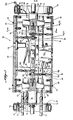
- apparatus 30 includes a plurality of mold segments 32 that are individually expansible and retractable and which together form a generally cylindrical mold.
- a packer 34 is provided at each end of the unit and is adapted to be expanded by the introduction of compressed air or the like so as to seal off the interior of the pipe between the packers.
- This volume can then be evacuated through operation of a suitable vacuum pump to a vacuum of preferably more than 750mm mercury, which is held during the coating operation to be described below.
- the mold assembly is expanded against the internal diameter of the pre-coatings 16 as shown in Figures 1 and 4 and urethane is injected by an injection valve 36 to create weld area coating section 2f shown in Figure 2.
- a vacuum could be pulled after the mold assembly has been expanded.
- the plurality of mold segments 32 of apparatus 30 preferably comprise a plurality of large mold segments 38 arranged in alternating relationship with a like plurality of small mold segments 40.
- Various numbers of large and small mold segments 38, 40 may be used. For most applications, however, three large mold segments and three small mold segments may be used to provide a mold for forming weld area coating section 24. It has been found that this number permits retraction of the mold to a size capable of negotiating field bends in the pipeline.
- a set of large and small mold segments 38, 40 will be needed for each diameter of pipe to be coated.
- slurry pipe applications for example, it is contemplated that most applications will be for 12-inch to 20-inch diameter pipe.
- a limited number of interchangeable mold segments will be needed for use with apparatus 30.
- mold segments 38, 40 are made of aluminum or steel and have an electroless nickel or other similar finish for smoothness so that the injected urethane does not stick to it.
- the surface of the mold segments may be sprayed with a commercially available mold release material such as a wax or silicone coating to prevent sticking. Any smooth surface will do which prevents sticking of the urethane.
- large mold segments 38 subtend an angle of approximately 100°.
- large mold segments 38 and small mold segments 40 together form a complete cylinder as seen in Figures 1, 4, and 8.
- Bevels 42 on the large mold segments sealingly cooperate with bevels 44 on the small mold segments.
- each mold segment 38, 40 is preferably provided with a sealing strip 46 located at each end in grooves 48 on the outer surface of the mold segment. Sealing strips 46 provide an additional seal against leakage of urethane injected into the weld area. Sealing strips 46 are located on opposite sides of the weld area and can withstand a pressure of approximately 300 to 400 psi.
- the sealing strips are made of elastomer.
- Bevels 42, 44 permit small mold segments 40 to act like a keystone in an arch so that the forces on the mold segments due to material injection can be substantially carried by the small mold segments.
- a double acting cylinder 50 extends from the center of apparatus 30 out to each end of large mold segments 38.
- a double acting cylinder 52 extends radially outward from the center of apparatus 30 to each end of each small mold segment.
- Cylinders 50, 52 are mounted on a long cylinder mount base 54 at one end of apparatus 30 and a small cylinder mount base 56 at the other end by two socket head cap screws 58.
- the long mount base 54 is necessary to provide enough space for the various hydraulic, coating supply, and pneumatic hoses and electrical lines entering apparatus 30.
- a piston rod 60 extends radially outward from each cylinder to its associated mold segment.
- a spring plate 62 is mounted on its associated piston rod 60 by a flat head cap screw 64.
- Small mold segments to are in turn held against spring plates 62 by a hex socket shoulder screw, washer, and spring assembly 66.
- Large mold segments 38 are likewise held against spring plates 62 by a flat head cap screw, nut, washer, and spring assembly 68.
- Assemblies 66, 68 permit slight misalignments of the mold segments due to uneven inward and outward movement of piston rods 60, and also make mold segments 38, 40 self-aligning when expanded.
- a spreader bar 70 is bolted to the inside end of each cylinder mount base 54, 56 by two hex head bolts 72. In turn, a pair of connecting bars 74 are bolted to and extend between spreader bars 70.
- a packer plate 76 is bolted to the outside end of each of cylinder mount bases 54, 56 by socket head cap screws 78. Packer plate 76 bolted to long cylinder mount base 54 has a plurality of penetrations extending through it for passage of the necessary hydraulic, pneumatic, and electrical lines for operation of apparatus 30. The opposed packer plate has penetrations for passage of a pneumatic line to supply packer 34.
- Packer 34 is positioned on packer retainer 81 which is bolted to packer plate 76 by a plurality of socket head cap screws 82.
- An aperture 84 in packer retainer 81 accommodates an air valve for packer 34.
- Each mounting bracket 86 supports two oppositely directed limit switch actuator assemblies 88, 89. Assemblies 88 are associated with large mold segments 38 and assemblies 89 are associated with small mold segments 40. Each mounting bracket 86 is connected to the connecting bars by a pair of socket head capscrews 90. Each limit switch actuator assembly 88, i9 is mounted in an aperture 92 which extends through mounting bracket 86. Apertures 92 have a large diameter portion 94.
- Each actuator assembly 88, 89 includes a damper control swivel 96 which is threaded into the associated mold segment and a linkage 98 threaded into the swivel.
- a pair of nuts 100 are threaded onto each linkage 98.
- a washer 102 is positioned on the linkage between two springs 104, 106.
- a nut 108 is threaded onto the opposite end of linkage 98 and retains a spring 110 and washer 112.
- An expansion limit switch 114 and a retraction limit switch 115 are mounted on mounting bracket 86 and associated with each limit switch actuator assembly 88.
- an expansion limit switch 116 and retraction limit switch 117 are mounted on mounting brackets 86 and associated with limit switch actuator assemblies 89.
- a pressure transducer 118 is mounted in a small mold segment 40 and communicates to the outside surface of the mold segment.
- An injection valve assembly 36 is mounted in a large mold segment 38. The assembly includes a valve body 122 and a valve cap 124 bolted to the valve body.
- valve body and valve cap 122, 124 define a hydraulic cylinder 126.
- a top hydraulic fluid inlet 128 and a bottom hydraulic fluid inlet 129 extend through the valve cap 124 and valve body 122, respectively, into hydraulic cylinder 126.
- a piston 130 is positioned reciprocatingly in hydraulic cylinder 126.
- a spool 132 Extending downwardly from piston 130 is a spool 132. It reciprocatingly resides in a central passage 134 which communicates out through large mold segment 38. Spool 132 has a smaller diameter central neck section 1?6. Extending through valve body 122 into central passage 134 is a castable urethane supply passage 138, a solvent supply passage 140, and a waste removal passage 142.
- the mold segments and injection valve are controlled by a hydraulic system shown schematically in Figure 9.
- the hydraulic system has a reservoir for the hydraulic fluid 150.
- the hydraulic fluid is pressurized and fed through a supply line 153 by a hydraulic pump 151.
- a relief valve 152 prevents any over pressurizing of the supply line.
- Back flow in return line 154 is prevented by a check valve 155.
- An unloading valve 156 permits dumping of the entire system.
- injection valve 36 Leading to injection valve 36 is a three position, four way blocked center control valve 157 which permits selection of hydraulic fluid flow to either top hydraulic fluid inlet 128 or bottom hydraulic fluid inlet 129.
- a dual flow control valve 158 restricts hydraulic fluid flow in order to provide smooth and controlled movement of the valve.
- relief valves 159 are provided just upstream of injection valve 36.
- the hydraulic system has a pressure reducing valve 160 to control the pressure of the hydraulic pump 151.
- a three position, four way control valve 161 directs the hydraulic fluid to flow to one or the other side of the piston in double acting cylinder 50.
- a pilot operated check valve 162 assures that hydraulic fluid is released from one side of the cylinder piston as hydraulic fluid is pumped into the other side of the piston.
- Dual flow control valves 163 control the flow of hydraulic fluid for controlled movement of the piston in cylinder 50.
- relief valves 164 are provided just upstream of cylinder 50. .
- the hydraulic control system for cylinders 52 have components corresponding to those for the system for cylinders 50, including a pressure reducing valve 165, a three position, four way control valve 166, a pilot operated dual check valve 167, a dual flow control valve 168, and a pair of relief valves 169.
- mold apparatus 30 may be provided with support wheel assemblies 169 extending from each end to permit the assembly to be rolled through a pipeline by manually pushing or pulling it.
- mold apparatus 30 be moved through a pipeline by a wheeled power unit 170 as shown in Figure 4.
- the power unit will contain a hydraulic drive motor 172 to power a drive wheel in order to move the apparatus through the pipeline.
- the power unit contain the hydraulic control valves 174 for controlling the hydraulic system for apparatus 30 and a mixer 176 for mixing a prepolymer and a hydrogen active chain extender to form the urethane which enters the injection valve.
- Power unit 170 can be connected to apparatus 30 by an appropriate linkage 178.
- a support wheel assembly 180 may be connected to the opposite end of apparatus 30 to support that end of the apparatus in the pipeline.
- the apparatus of the present invention operates as follows. After consecutive pipe sections have, been welded together to form a pipeline as described above, mold apparatus 30 is moved into position at a weld by power unit 170. Various methods can be used to properly locate apparatus 30 at a weld. For example, the location of apparatus 30 could simply be measured from the end of the pipeline. Another method would be to provide a sensing device on the apparatus to sense the polarity difference across a weld 12. Also, a switch 182 could be used to sense the end of the pre-coating 16 at a weld.
- packers 34 are inflated pneumatically to seal off the area of the pipeline between the packers. When this seal has been made, the space between packers 34 is evacuated to a vacuum of more than 750 millimeters of mercury. This vacuum is held during the injection operation.
- expansible mold segments 32 are expanded into contact with pre-coating 16 as in Figure 8.
- Large mold segments 38 are first expanded outwardly by applying hydraulic pressure to cylinders 50.
- washer 112 will trip limit switch 114.
- Small mold segments 40 are now permitted to expand outwardly under hydraulic pressure applied to cylinders 52.
- washer 112 will trip limit switch 116, indicating that the injection process may begin.
- Any irregularities on the inside surface of pre-coating 16 are accommodated by sealing strips 46. Any misalignment of the mold segments which may occur during the expansion of the mold segments is accommodated by spring plates 62 and assemblies 66, 68.
- bevels 42, 44 permit tight engagement between large and small mold segments 38, 40.
- Small mold segments 40 simply will not be fully expanded to a position flush with the outside surface of the large mold segments. .
- annular space 184 is defined by the outside surface of the mold segments, the ends of the pre-coatings 16, and the inside surface 22 of the pipeline. It is into this annular space that the urethane coating will be injected.
- a castable urethane is the injected material.
- the injection valve is in its initial closed position. Castable urethane enters central passage 134 through supply passage 138 and is directed out through waste passage 142. Mixer 176 and the lines connecting the mixer to valve 120 will initially contain solvent from a previous joint injection. Thus, at the start of the urethane injection cycle, the remaining solvent and mixed urethane is displaced through passage 134 and out waste removal passage 142 until a steady state urethane stream is achieved at the injection valve. At that time, the valve is opened to the position shown in Figure 6 by supplying hydraulic pressure to cylinder 126 through inlet 129.
- the mixed castable urethane is directed into annular space 184. Because a vacuum is maintained in the space between packers 34 during the entire injection operation, the annular space is completely filled by the urethane.
- Pressure sensor 118 senses a pressure rise as the annular space 184 is completely filled, signaling the valve to be closed to the position shown in Figure 5 by supplying hydraulic pressure through inlet 128.
- valve 120 During the injection operation, solvent is applied into valve 120 through solvent supply passage 140 and exits through waste removal passage 142. The valve is thereby cleaned of mixed urethane.
- solvent is injected at the mixer to wash the remaining urethane out of the mixer, the feed hoses, and the valve to the waste tank. This is done with the valve in the closed position shown in Figure 5.
- mold segments 38, 40 can be retracted to the position shown in Figure 8A and packers 34 can be deflated.
- Small mold segments 40 are retracted first by supplying hydraulic pressure to cylinders 52.
- washers 102 trip retraction limit switches 117.
- large mold segments 38 can be retracted.
- washers 102 trip limit switches 115, signaling that all mold segments are fully retracted.
- mandrel assembly 30 With the mold segments retracted, mandrel assembly 30 can be moved to another weld area in the pipeline. It is important that the outer dimensions of assembly 30 permit it to retract to such a size that it can be powered around bends in pipeline 14. Such bends may be field formed to a radius as small as about twenty times the outside diameter of the pipe for sizes up to and including 36.0 O.D. inches or to a radius of 60 feet for larger sizes of pipe.
Landscapes
- Engineering & Computer Science (AREA)
- Mechanical Engineering (AREA)
- General Engineering & Computer Science (AREA)
- Manufacturing & Machinery (AREA)
- Lining Or Joining Of Plastics Or The Like (AREA)
- Protection Of Pipes Against Damage, Friction, And Corrosion (AREA)
- Coating Apparatus (AREA)
- Non-Disconnectible Joints And Screw-Threaded Joints (AREA)
- Moulds For Moulding Plastics Or The Like (AREA)
Applications Claiming Priority (2)
| Application Number | Priority Date | Filing Date | Title |
|---|---|---|---|
| US697473 | 1985-02-01 | ||
| US06/697,473 US4780072A (en) | 1985-02-01 | 1985-02-01 | Apparatus for internally coating welded pipe at the weldment |
Publications (2)
| Publication Number | Publication Date |
|---|---|
| EP0189934A2 true EP0189934A2 (de) | 1986-08-06 |
| EP0189934A3 EP0189934A3 (de) | 1987-08-19 |
Family
ID=24801260
Family Applications (1)
| Application Number | Title | Priority Date | Filing Date |
|---|---|---|---|
| EP86101284A Withdrawn EP0189934A3 (de) | 1985-02-01 | 1986-01-31 | Verfahren und Vorrichtung zum Aufbringen einer Innenschicht zum Schutz der Verbindungsstellen von geschweissten Rohrleitungen |
Country Status (5)
| Country | Link |
|---|---|
| US (1) | US4780072A (de) |
| EP (1) | EP0189934A3 (de) |
| JP (1) | JPS61215885A (de) |
| AU (1) | AU5323986A (de) |
| ZA (1) | ZA86750B (de) |
Cited By (9)
| Publication number | Priority date | Publication date | Assignee | Title |
|---|---|---|---|---|
| EP0287429A1 (de) * | 1987-04-16 | 1988-10-19 | Elf Atochem S.A. | Herstellungsverfahren von an ihren Enden verbundenen Metallröhren |
| EP0497701A1 (de) * | 1991-02-01 | 1992-08-05 | Automobiles Peugeot | Verfahren zur Herstellung eines elastischen Gelenkes, Kern für die Durchführung des Verfahrens und hergestelltes Gelenk |
| RU2329431C2 (ru) * | 2006-09-05 | 2008-07-20 | Денис Николаевич Воронин | Способ установки протектора в концевой части трубы с внутренним защитным покрытием |
| CN103216688A (zh) * | 2013-05-03 | 2013-07-24 | 周跃飞 | 一种金属管件的焊接方法 |
| EP2926969A1 (de) * | 2014-04-01 | 2015-10-07 | Airbus Operations GmbH | Verfahren zur Herstellung einer gedruckten 3D-Hohlstruktur mit glatter Innenfläche, und gedruckte 3D-Hohlstruktur |
| CN110900102A (zh) * | 2019-12-17 | 2020-03-24 | 贵溪华泰铜业有限公司 | 一种用于紫铜管接口加工的焊接装置 |
| CN113732148A (zh) * | 2021-11-05 | 2021-12-03 | 太原科技大学 | 一种厚壁金属直缝焊管板边全液压预弯装置及方法 |
| CN115234717A (zh) * | 2022-06-21 | 2022-10-25 | 中国平煤神马控股集团有限公司 | 一种输送管道的高效保温结构 |
| CN117101970A (zh) * | 2023-09-06 | 2023-11-24 | 杭州华昱金属制品有限公司 | 一种金属材料表面防腐蚀处理设备及其处理工艺 |
Families Citing this family (19)
| Publication number | Priority date | Publication date | Assignee | Title |
|---|---|---|---|---|
| US5388863A (en) * | 1993-07-20 | 1995-02-14 | Saudi Arabian Oil Company | Method and apparatus for joining in-situ cement-mortar lined pipelines |
| US5516415A (en) * | 1993-11-16 | 1996-05-14 | Ontario Hydro | Process and apparatus for in situ electroforming a structural layer of metal bonded to an internal wall of a metal tube |
| FR2852538B1 (fr) * | 2003-03-21 | 2006-09-15 | France Etat Armement | Dispositif et procede utilises pour realiser le chemisage d'une capacite de forme tubulaire |
| WO2006081241A2 (en) * | 2005-01-27 | 2006-08-03 | Inland Waters Pollution Control, Inc. | Pipeline cleaning apparatus |
| JP2008264637A (ja) * | 2007-04-17 | 2008-11-06 | Chugoku Electric Power Co Inc:The | 管内塗布装置 |
| US9004003B2 (en) * | 2009-06-25 | 2015-04-14 | Xerox Corporation | Apparatus for applying an acoustic dampening coating to the interior of a xerographic drum |
| US8513559B2 (en) * | 2010-12-23 | 2013-08-20 | Swa Holding Company, Inc. | Apparatus for applying wear coating in conduit elbows |
| GB201116476D0 (en) * | 2011-09-26 | 2011-11-09 | Rolls Royce Plc | Mandrel for forming a component |
| US10160067B2 (en) * | 2013-05-10 | 2018-12-25 | Illinois Tool Works Inc. | Data acquisition using a purge plug |
| US20150184785A1 (en) * | 2013-12-27 | 2015-07-02 | Edward Thomas Richards, JR. | System and method for repair and maintenance of pipelines |
| US9808991B2 (en) | 2014-07-29 | 2017-11-07 | Cc3D Llc. | Method and apparatus for additive mechanical growth of tubular structures |
| US9903521B2 (en) * | 2014-10-01 | 2018-02-27 | Richard L. Glenn | Upstream pipe plug |
| CN105397965B (zh) * | 2015-12-04 | 2017-06-16 | 德州学院 | 一种冷热转换控制器 |
| CN107638991A (zh) * | 2017-09-28 | 2018-01-30 | 高祥桐 | 一种用于管道内径焊缝的密封装置 |
| DK3935301T3 (da) * | 2019-04-29 | 2023-03-13 | Sms Group Gmbh | Metalrør til transport af olie og gas med en metalbelægning i et overgangsområde |
| RU2716789C1 (ru) * | 2019-06-20 | 2020-03-16 | Александр Георгиевич Чуйко | Устройство для роботизированной внутренней изоляции сварного стыка трубопровода |
| US20210299958A1 (en) * | 2020-03-28 | 2021-09-30 | Karl Joseph Dodds Gifford | Shrinkable platform for 3D printer |
| GB2628667A (en) * | 2023-03-31 | 2024-10-02 | Subsea 7 Ltd | Adapting hydrocarbon pipelines to transport hydrogen |
| CN119309951B (zh) * | 2024-12-18 | 2025-02-25 | 山西华重装备有限公司 | 销套耐磨性耦合试验机 |
Family Cites Families (31)
| Publication number | Priority date | Publication date | Assignee | Title |
|---|---|---|---|---|
| US1505004A (en) * | 1920-09-20 | 1924-08-12 | Mare Thomas De La | Conduit mold |
| US2140298A (en) * | 1936-03-18 | 1938-12-13 | Barrett Co | Apparatus for coating interior surfaces of tubular structures |
| US2399321A (en) * | 1945-05-14 | 1946-04-30 | American Pipe & Constr Co | Pipe lining machine |
| FR992388A (fr) * | 1949-08-10 | 1951-10-17 | Bataafsche Petroleum | Procédé de confection des joints de tuyaux |
| US3022765A (en) * | 1958-04-03 | 1962-02-27 | Cons Edison Co New York Inc | Method and apparatus for interior coating of pipes |
| US2908248A (en) * | 1958-04-25 | 1959-10-13 | Robert J Brant | Apparatus for cleaning and repairing pipe lines |
| US3017855A (en) * | 1959-06-15 | 1962-01-23 | American Pipe And Coustruction | Apparatus for applying a coating to joints in pipelines |
| US3055339A (en) * | 1961-02-27 | 1962-09-25 | Jersey Prod Res Co | Liquid coating applicator for inner surfaces of pipe strings |
| US3315017A (en) * | 1963-12-13 | 1967-04-18 | Koppers Co Inc | Gasproofing leaking gas main |
| US3269421A (en) * | 1964-02-11 | 1966-08-30 | Halliburton Co | Packer for grouting conduits |
| US3568721A (en) * | 1969-03-18 | 1971-03-09 | Reintjes Ind Services Of Louis | Tube repair tool |
| GB1389212A (en) * | 1971-02-18 | 1975-04-03 | British Steel Corp | Cylindrical moulding mandrel |
| BE789118A (fr) * | 1971-09-25 | 1973-01-15 | Kessel Bernhard | Procede pour la realisation de tubes a partir de matieres a mouler par injection |
| US3894131A (en) * | 1972-05-18 | 1975-07-08 | Minnesota Mining & Mfg | Poly(urethane-urea) sealants and sealing underground structures therewith |
| US3927360A (en) * | 1972-11-30 | 1975-12-16 | Leeds & Northrup Co | Null-balance servo system |
| DE2706649A1 (de) * | 1977-02-23 | 1978-08-24 | Pilgrim Eng Dev | Rohrverbindung und verfahren zu deren herstellung |
| US4240775A (en) * | 1977-06-02 | 1980-12-23 | Alberto Berni | Implementation for applying a lining to the inner wall of a tubular article |
| US4092950A (en) * | 1977-06-20 | 1978-06-06 | Commercial Resins Company | Internal pipe coating apparatus |
| FR2434330A1 (fr) * | 1978-08-25 | 1980-03-21 | Ato Chimie | Conduites pour ecoulements diphasiques |
| JPS56118833A (en) * | 1980-02-26 | 1981-09-18 | Toshiba Mach Co Ltd | Mold for forming |
| US4383819A (en) * | 1980-07-16 | 1983-05-17 | Letica Corporation | Apparatus for forming a container |
| US4357745A (en) * | 1981-03-16 | 1982-11-09 | Uniroyal, Inc. | Method of welding lined pipe |
| US4360961A (en) * | 1981-03-16 | 1982-11-30 | Uniroyal, Inc. | Method of welding lined pipe |
| US4340010A (en) * | 1981-04-13 | 1982-07-20 | Commercial Resins Company | Internal girth coating apparatus |
| US4413655A (en) * | 1981-04-14 | 1983-11-08 | Brown George T | Pipe repair bypass system |
| US4389180A (en) * | 1981-06-25 | 1983-06-21 | Gordon John H | Mandrel with identical expanding segments |
| SE453642B (sv) * | 1982-06-18 | 1988-02-22 | Flutron Ab | Forfarande for beleggning av en yta genom att tillfora en vetska under tryck, varvid ytan forst utsettes for vakuum och derefter for tryck |
| US4421698A (en) * | 1982-08-16 | 1983-12-20 | Vanderlans Gerald J | Sealing device for use in grouting pipe joints and method of using same |
| JPS59150715A (ja) * | 1983-02-16 | 1984-08-29 | Daiichi Gaiyaa Kk | 金型部材 |
| DE3415561A1 (de) * | 1984-04-26 | 1985-11-07 | Neuhaus Stahlbau GmbH, 2875 Ganderkesee | Ziehkern fuer die herstellung eines aus beton, vorzugsweise leichtbeton giessbaren mantelabschnitts eines schornsteinmantels |
| FR2564938B1 (fr) * | 1984-05-24 | 1986-11-28 | Atochem | Nouveau raccord de tubes revetus interieurement et son procede de fabrication |
-
1985
- 1985-02-01 US US06/697,473 patent/US4780072A/en not_active Expired - Fee Related
-
1986
- 1986-01-31 ZA ZA86750A patent/ZA86750B/xx unknown
- 1986-01-31 EP EP86101284A patent/EP0189934A3/de not_active Withdrawn
- 1986-02-01 JP JP61021087A patent/JPS61215885A/ja active Pending
- 1986-02-03 AU AU53239/86A patent/AU5323986A/en not_active Abandoned
Cited By (15)
| Publication number | Priority date | Publication date | Assignee | Title |
|---|---|---|---|---|
| EP0287429A1 (de) * | 1987-04-16 | 1988-10-19 | Elf Atochem S.A. | Herstellungsverfahren von an ihren Enden verbundenen Metallröhren |
| FR2614086A1 (fr) * | 1987-04-16 | 1988-10-21 | Atochem | Tubes metalliques assembles par leurs extremites, procede de fabrication et appareillage pour sa mise en oeuvre |
| US5009737A (en) * | 1987-04-16 | 1991-04-23 | Atochem | Method of joining pipes at their ends to form a pipeline |
| EP0497701A1 (de) * | 1991-02-01 | 1992-08-05 | Automobiles Peugeot | Verfahren zur Herstellung eines elastischen Gelenkes, Kern für die Durchführung des Verfahrens und hergestelltes Gelenk |
| FR2672235A1 (fr) * | 1991-02-01 | 1992-08-07 | Peugeot | Procede de realisation d'une articulation elastique, noyau utilisable dans ce procede et articulation obtenue. |
| RU2329431C2 (ru) * | 2006-09-05 | 2008-07-20 | Денис Николаевич Воронин | Способ установки протектора в концевой части трубы с внутренним защитным покрытием |
| CN103216688A (zh) * | 2013-05-03 | 2013-07-24 | 周跃飞 | 一种金属管件的焊接方法 |
| EP2926969A1 (de) * | 2014-04-01 | 2015-10-07 | Airbus Operations GmbH | Verfahren zur Herstellung einer gedruckten 3D-Hohlstruktur mit glatter Innenfläche, und gedruckte 3D-Hohlstruktur |
| CN110900102A (zh) * | 2019-12-17 | 2020-03-24 | 贵溪华泰铜业有限公司 | 一种用于紫铜管接口加工的焊接装置 |
| CN110900102B (zh) * | 2019-12-17 | 2022-12-13 | 贵溪华泰铜业有限公司 | 一种用于紫铜管接口加工的焊接装置 |
| CN113732148A (zh) * | 2021-11-05 | 2021-12-03 | 太原科技大学 | 一种厚壁金属直缝焊管板边全液压预弯装置及方法 |
| CN113732148B (zh) * | 2021-11-05 | 2022-01-18 | 太原科技大学 | 一种厚壁金属直缝焊管板边全液压预弯装置及方法 |
| CN115234717A (zh) * | 2022-06-21 | 2022-10-25 | 中国平煤神马控股集团有限公司 | 一种输送管道的高效保温结构 |
| CN115234717B (zh) * | 2022-06-21 | 2023-09-22 | 中国平煤神马控股集团有限公司 | 一种输送管道的高效保温结构 |
| CN117101970A (zh) * | 2023-09-06 | 2023-11-24 | 杭州华昱金属制品有限公司 | 一种金属材料表面防腐蚀处理设备及其处理工艺 |
Also Published As
| Publication number | Publication date |
|---|---|
| ZA86750B (en) | 1986-11-26 |
| US4780072A (en) | 1988-10-25 |
| JPS61215885A (ja) | 1986-09-25 |
| EP0189934A3 (de) | 1987-08-19 |
| AU5323986A (en) | 1986-08-07 |
Similar Documents
| Publication | Publication Date | Title |
|---|---|---|
| US4780072A (en) | Apparatus for internally coating welded pipe at the weldment | |
| US4178875A (en) | Apparatuses for producing tight joints or seals in underground pipelines | |
| US5009737A (en) | Method of joining pipes at their ends to form a pipeline | |
| US4413653A (en) | Inflation anchor | |
| US3642291A (en) | Inflatable seal | |
| EP0122099B1 (de) | Verbindung und Abdichtung rohrartiger Teile | |
| IE71184B1 (en) | Improvements in methods for installing a substantially rigid thermoplastic pipe in an existing conduit | |
| GB1591409A (en) | Methods of and apparatuses for producing fluid tight joints or seals in underground pipelines | |
| US5462706A (en) | Method for forming a flange on an end of a synthetic liner | |
| US4360961A (en) | Method of welding lined pipe | |
| US20220082196A1 (en) | Expandable pipe including a liner for restoring a conduit | |
| US4827984A (en) | Method of repairing or replacing piping and inflatable plug | |
| JP2003505657A (ja) | 分岐用継手をパイプラインに連結する方法 | |
| US20060112996A1 (en) | Treatment of pipes | |
| CA3078181C (en) | Device for the internal monolithic insulation of a welded pipeline joint | |
| AU2002321600A1 (en) | Tee connection to a pipeline | |
| AU2021230065A1 (en) | Device and method for sealing or repairing a leaking and/or damaged location on an inner wall of a pipe | |
| US3951173A (en) | Method and apparatus for sealing large diameter pipes | |
| RU2240466C2 (ru) | Устройство для многоразовой герметизации внутренней полости открытого конца трубопровода | |
| RU2374551C2 (ru) | Способ ремонта дефектных участков трубопроводов | |
| JPS5922394Y2 (ja) | ガス管の漏洩修理機 | |
| KR102062043B1 (ko) | 고확장성을 가진 관로 보수용 패커 장치 | |
| GB2609905A (en) | Mould for coating pipeline sections | |
| US2162431A (en) | Pipe joint | |
| MXPA01006726A (es) | Un forro e tubo, un producto de forro y metodos para formar e instalar el forro. |
Legal Events
| Date | Code | Title | Description |
|---|---|---|---|
| PUAI | Public reference made under article 153(3) epc to a published international application that has entered the european phase |
Free format text: ORIGINAL CODE: 0009012 |
|
| AK | Designated contracting states |
Kind code of ref document: A2 Designated state(s): AT BE CH DE FR GB IT LI LU NL |
|
| PUAL | Search report despatched |
Free format text: ORIGINAL CODE: 0009013 |
|
| AK | Designated contracting states |
Kind code of ref document: A3 Designated state(s): AT BE CH DE FR GB IT LI LU NL |
|
| 17P | Request for examination filed |
Effective date: 19880218 |
|
| 17Q | First examination report despatched |
Effective date: 19880704 |
|
| STAA | Information on the status of an ep patent application or granted ep patent |
Free format text: STATUS: THE APPLICATION IS DEEMED TO BE WITHDRAWN |
|
| 18D | Application deemed to be withdrawn |
Effective date: 19881017 |