EP0189689A1 - Elektrischer Schalter mit Blende - Google Patents
Elektrischer Schalter mit Blende Download PDFInfo
- Publication number
- EP0189689A1 EP0189689A1 EP85402426A EP85402426A EP0189689A1 EP 0189689 A1 EP0189689 A1 EP 0189689A1 EP 85402426 A EP85402426 A EP 85402426A EP 85402426 A EP85402426 A EP 85402426A EP 0189689 A1 EP0189689 A1 EP 0189689A1
- Authority
- EP
- European Patent Office
- Prior art keywords
- screen
- arc
- switching device
- switch
- movable contact
- Prior art date
- Legal status (The legal status is an assumption and is not a legal conclusion. Google has not performed a legal analysis and makes no representation as to the accuracy of the status listed.)
- Granted
Links
- 239000008188 pellet Substances 0.000 claims description 7
- 238000006073 displacement reaction Methods 0.000 claims description 5
- 239000004020 conductor Substances 0.000 description 5
- 230000005520 electrodynamics Effects 0.000 description 3
- 230000008901 benefit Effects 0.000 description 2
- 230000001687 destabilization Effects 0.000 description 2
- 230000000694 effects Effects 0.000 description 2
- 239000000463 material Substances 0.000 description 2
- 230000008961 swelling Effects 0.000 description 2
- 206010020772 Hypertension Diseases 0.000 description 1
- 230000006866 deterioration Effects 0.000 description 1
- 230000002349 favourable effect Effects 0.000 description 1
- 238000005194 fractionation Methods 0.000 description 1
- 239000007789 gas Substances 0.000 description 1
- 238000002955 isolation Methods 0.000 description 1
- 238000005259 measurement Methods 0.000 description 1
- 229910000510 noble metal Inorganic materials 0.000 description 1
Images
Classifications
-
- H—ELECTRICITY
- H01—ELECTRIC ELEMENTS
- H01H—ELECTRIC SWITCHES; RELAYS; SELECTORS; EMERGENCY PROTECTIVE DEVICES
- H01H9/00—Details of switching devices, not covered by groups H01H1/00 - H01H7/00
- H01H9/30—Means for extinguishing or preventing arc between current-carrying parts
- H01H9/32—Insulating body insertable between contacts
Definitions
- the invention relates to a screen switch device having, on the one hand, two contact parts movable with respect to each other between a closed state where the contact pads touch each other, and an open state where the pads are separated and, on the other hand, an insulating screen which is rapidly interposed between the pellets by performing from a starting position towards a working position, a movement during which the arc appearing at the opening is moved by an active edge of the screen and at the end of which the arc is completely destabilized.
- Electric switches are already known using arc deflector devices, which take the form of horns placed in the vicinity of the contact pads on the free ends of the contact parts, and which have, with respect to the general direction of these parts , a change of orientation such as the natural development of the arc effected under the effect of electro-dynamic repulsion forces, brings the feet of these arcs on these horns and consequently avoids their parking on said pellets.
- the orientations, curvatures, shapes or positions given to these horns are essentially based on the assumption that the current flowing in the arc is high enough for this development to be possible 1 the same measurements can be taken if a development or a swelling of the arc is assisted by the presence of a local magnetic field, which can be induced or permanent and which is suitably oriented to favor the speed of displacement.
- the desired increase in the arc voltage results from its elongation, while the fact of installing the feet of these arcs on the horns avoids consumption of the noble metal of the contact pads; in these known devices, the orientations of these horns are generally divergent.
- the invention therefore proposes to bring to a screen switch, the general constitution of which corresponds to that which is mentioned above, improvements capable of considerably reducing the wear of the contact pads and, consequently, practically eliminating the drawbacks which result therefrom, in particular when the size of the switch, the level of fault currents to be interrupted and the size of the device which uses it, make it difficult to implement other means.
- each support piece comprises, beyond the corresponding pad, a conductive deflector extension respectively, these extensions being oriented or shaped so that for each pair of positions of the contacts and from the edge of the screen, following the passage of the latter between the pads, there exists between two points of these extensions a possible arc path which passes through a point of this edge, and which is shorter than the path passing at this time there by the pellets and said point of the edge.
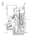
- a switch 1, see FIG. 1, implementing the invention mainly comprises a first contact piece 2 which, here, is fixed, and which therefore carries a fixed contact pad 4, a movable contact piece 3 which, here , is represented by a lever 5 pivoting about an axis 9 and carrying a movable contact 7, elastic means 6 which provide the necessary contact pressure, a flexible current supply conductor 11, a mechanical means 10 making it possible to operate the opening of the contacts, a thin insulating screen 17, which is guided in an insulating housing 12 for example along grooves 13 thereof to establish effective isolation between its two opposite faces, and a slot or transverse groove 14 , which is carried by a wall 15 of the shoemaker, which is connected to an expansion channel 19, and which is placed near the switch to receive the edge 16 of the screen when the latter moves to the left between a starting point or 10, and a point of arrival or work 8.
- the screen 17 can, for example, be propelled at the moment of the appearance of an overcurrent of current J by the mechanism 10 when the latter is released by the effects of a coil 26 placed in series in the circuit 18 which also includes a conductor 27 between terminals 24, 25; in a first variant, the screen can be propelled by a previously armed elastic means 29 which is itself released by a pallet, or core, or striker 30 associated with the coil 26 or by the mechanism 10.
- Resetting means not illustrated make it possible to restore to the mobile contact and to the screen, after automatic opening, rest positions identical to those of FIG. 1.
- the edge of the screen arrives with a high speed between the two contact pads, when the latter are momentarily separated by an amount slightly greater than its thickness -e-. It then operates a destabilization of the arc when it abuts against the wall or when the front edge of the screen enters the slot 14 when it exists.
- the contact pieces have been provided with conductive extensions, deflectors 20 and 21 respectively, which are directed in the directions of movement Q of the screen, and whose facing surfaces 22, 23, unlike the previous arrangements of the horns, do not diverge significantly, at least in regions immediately adjacent to these pellets.
- the breaking chamber 28 and therefore the movement of the movable contact are small.
- the surfaces where the arc feet circulate preferably extend as far as the vicinity of the slot in the housing into which the end of the screen penetrates, and that the angular travel performed by the movable contact when carried by a pivoting lever, must not be too high so as not to establish for a certain relative position of the screen and the lever, a shorter path than that existing during a immediately preceding relative position.
- the extension 21 which is substantially parallel to the region 22 adjacent to the patch fixed contact 4 at the time of opening, forms an angle ⁇ with the general direction of the lever passing through points 9 and 7, while the deflector 20 itself has a surface 22a forming an angle with the general direction of conductor support 2, itself parallel to the screen.
- the angular travel of the lever is here also relatively small, which allows the use of a mechanism 10 of reduced volume.
- the presence of the inclined surface 22a promotes, moreover, the evacuation of the gases appearing at the time of cutting to an evacuation channel 19a.
Landscapes
- Arc-Extinguishing Devices That Are Switches (AREA)
- Mechanisms For Operating Contacts (AREA)
- Push-Button Switches (AREA)
- Driving Mechanisms And Operating Circuits Of Arc-Extinguishing High-Tension Switches (AREA)
- Automatic Cycles, And Cycles In General (AREA)
- Current-Collector Devices For Electrically Propelled Vehicles (AREA)
- Cookers (AREA)
- Electrophonic Musical Instruments (AREA)
- Input Circuits Of Receivers And Coupling Of Receivers And Audio Equipment (AREA)
- Motorcycle And Bicycle Frame (AREA)
- Electrical Discharge Machining, Electrochemical Machining, And Combined Machining (AREA)
- Switches That Are Operated By Magnetic Or Electric Fields (AREA)
- Automatic Disk Changers (AREA)
- Operating, Guiding And Securing Of Roll- Type Closing Members (AREA)
- Switches With Compound Operations (AREA)
- Oscillators With Electromechanical Resonators (AREA)
- Supplying Of Containers To The Packaging Station (AREA)
Priority Applications (1)
| Application Number | Priority Date | Filing Date | Title |
|---|---|---|---|
| AT85402426T ATE44110T1 (de) | 1984-12-28 | 1985-12-06 | Elektrischer schalter mit blende. |
Applications Claiming Priority (2)
| Application Number | Priority Date | Filing Date | Title |
|---|---|---|---|
| FR8419993 | 1984-12-28 | ||
| FR8419993A FR2575589B1 (fr) | 1984-12-28 | 1984-12-28 | Interrupteur electrique a ecran |
Publications (2)
| Publication Number | Publication Date |
|---|---|
| EP0189689A1 true EP0189689A1 (de) | 1986-08-06 |
| EP0189689B1 EP0189689B1 (de) | 1989-06-14 |
Family
ID=9311085
Family Applications (1)
| Application Number | Title | Priority Date | Filing Date |
|---|---|---|---|
| EP85402426A Expired EP0189689B1 (de) | 1984-12-28 | 1985-12-06 | Elektrischer Schalter mit Blende |
Country Status (14)
| Country | Link |
|---|---|
| US (1) | US4659888A (de) |
| EP (1) | EP0189689B1 (de) |
| JP (1) | JPS61161626A (de) |
| AT (1) | ATE44110T1 (de) |
| BR (1) | BR8506471A (de) |
| CA (1) | CA1250010A (de) |
| CH (1) | CH666764A5 (de) |
| DE (1) | DE3544864C2 (de) |
| ES (1) | ES8703676A1 (de) |
| FR (1) | FR2575589B1 (de) |
| GB (1) | GB2169141B (de) |
| IE (1) | IE57188B1 (de) |
| IT (1) | IT1186171B (de) |
| ZA (1) | ZA859818B (de) |
Cited By (2)
| Publication number | Priority date | Publication date | Assignee | Title |
|---|---|---|---|---|
| EP0310469A1 (de) * | 1987-10-02 | 1989-04-05 | Telemecanique | Schutzschalter mit Blende zum Unterbrechen des Lichtbogens |
| EP0310468A1 (de) * | 1987-10-02 | 1989-04-05 | Telemecanique | Schutzschalter mit Blende zum Unterbrechen des Lichtbogens |
Families Citing this family (6)
| Publication number | Priority date | Publication date | Assignee | Title |
|---|---|---|---|---|
| US4752660A (en) * | 1986-01-10 | 1988-06-21 | Matsushita Electric Works, Ltd. | Current limiting circuit breaker with an arc shearing plate |
| EP0244276B1 (de) * | 1986-04-04 | 1991-06-05 | Telemecanique | Elektrischer Schalter für Schutzgerät, wie Schutzschalter |
| DE3823790A1 (de) * | 1988-07-14 | 1990-01-18 | Asea Brown Boveri | Elektrisches installationsgeraet mit kontakttrennwand |
| DE19710880B4 (de) * | 1997-03-15 | 2007-11-15 | Moeller Gmbh | Lichtbogenlöscheinrichtung |
| DE19735521A1 (de) * | 1997-08-16 | 1999-02-18 | Kloeckner Moeller Gmbh | Lichtbogenlöscheinrichtung für einen kurzschlußstrombegrenzenden Niederspannungsschalter |
| JP5758169B2 (ja) * | 2011-03-31 | 2015-08-05 | Nkkスイッチズ株式会社 | 消弧装置付き直流電流遮断用小形スイッチ |
Citations (4)
| Publication number | Priority date | Publication date | Assignee | Title |
|---|---|---|---|---|
| FR1238660A (fr) * | 1958-10-16 | 1960-08-12 | Siemens Ag | Dispositif pour allonger les arcs électriques |
| FR1541810A (fr) * | 1967-09-01 | 1968-10-11 | Comp Generale Electricite | Appareil électrique de coupure à rupture rapide |
| DE2508299A1 (de) * | 1974-03-12 | 1975-09-25 | Ahlstroem Oy | Elektrisches schaltgeraet |
| FR2511185A1 (fr) * | 1981-08-07 | 1983-02-11 | Telemecanique Electrique | Dispositif automatique de limitation de courants de court-circuit |
Family Cites Families (7)
| Publication number | Priority date | Publication date | Assignee | Title |
|---|---|---|---|---|
| FR570840A (fr) * | 1923-10-04 | 1924-05-07 | Interrupteur à air à action rapide | |
| US2020935A (en) * | 1932-05-25 | 1935-11-12 | Westinghouse Electric & Mfg Co | Circuit interrupter |
| US3549840A (en) * | 1968-07-18 | 1970-12-22 | S & C Electric Co | Switch construction with load break device |
| DE1957620A1 (de) * | 1969-11-15 | 1971-05-27 | Karl Ahrens | Leistungsschalter |
| US3842228A (en) * | 1973-08-27 | 1974-10-15 | Us Navy | Circuit breaker assembly with interposed wedge non-conductor and complementary housing arc-prevention structure |
| US3978300A (en) * | 1975-02-11 | 1976-08-31 | Westinghouse Electric Corporation | Low-voltage circuit-breaker having small contact separation and small gap between cooperating parallel-arranged arcing-rails |
| FR2540665B1 (fr) * | 1983-02-04 | 1987-02-27 | Telemecanique Electrique | Dispositif interrupteur muni d'un ecran isolant s'interposant entre les contacts lors de la coupure et de moyen de cisaillement de l'arc entre cet ecran et une paroi isolante |
-
1984
- 1984-12-28 FR FR8419993A patent/FR2575589B1/fr not_active Expired
-
1985
- 1985-12-06 AT AT85402426T patent/ATE44110T1/de not_active IP Right Cessation
- 1985-12-06 EP EP85402426A patent/EP0189689B1/de not_active Expired
- 1985-12-12 GB GB8530582A patent/GB2169141B/en not_active Expired
- 1985-12-17 CA CA000497920A patent/CA1250010A/fr not_active Expired
- 1985-12-18 DE DE3544864A patent/DE3544864C2/de not_active Expired - Fee Related
- 1985-12-19 CH CH5432/85A patent/CH666764A5/fr not_active IP Right Cessation
- 1985-12-20 IT IT23341/85A patent/IT1186171B/it active
- 1985-12-23 US US06/812,599 patent/US4659888A/en not_active Expired - Fee Related
- 1985-12-23 BR BR8506471A patent/BR8506471A/pt not_active IP Right Cessation
- 1985-12-23 ZA ZA859818A patent/ZA859818B/xx unknown
- 1985-12-23 IE IE3309/85A patent/IE57188B1/xx unknown
- 1985-12-27 JP JP60299822A patent/JPS61161626A/ja active Pending
- 1985-12-27 ES ES550490A patent/ES8703676A1/es not_active Expired
Patent Citations (4)
| Publication number | Priority date | Publication date | Assignee | Title |
|---|---|---|---|---|
| FR1238660A (fr) * | 1958-10-16 | 1960-08-12 | Siemens Ag | Dispositif pour allonger les arcs électriques |
| FR1541810A (fr) * | 1967-09-01 | 1968-10-11 | Comp Generale Electricite | Appareil électrique de coupure à rupture rapide |
| DE2508299A1 (de) * | 1974-03-12 | 1975-09-25 | Ahlstroem Oy | Elektrisches schaltgeraet |
| FR2511185A1 (fr) * | 1981-08-07 | 1983-02-11 | Telemecanique Electrique | Dispositif automatique de limitation de courants de court-circuit |
Cited By (4)
| Publication number | Priority date | Publication date | Assignee | Title |
|---|---|---|---|---|
| EP0310469A1 (de) * | 1987-10-02 | 1989-04-05 | Telemecanique | Schutzschalter mit Blende zum Unterbrechen des Lichtbogens |
| EP0310468A1 (de) * | 1987-10-02 | 1989-04-05 | Telemecanique | Schutzschalter mit Blende zum Unterbrechen des Lichtbogens |
| FR2621417A1 (fr) * | 1987-10-02 | 1989-04-07 | Telemecanique Electrique | Interrupteur de protection a ecran de coupure d'arc |
| FR2621418A1 (fr) * | 1987-10-02 | 1989-04-07 | Telemecanique Electrique | Interrupteur de protection a ecran de coupure d'arc |
Also Published As
| Publication number | Publication date |
|---|---|
| FR2575589B1 (fr) | 1987-02-06 |
| GB2169141A (en) | 1986-07-02 |
| DE3544864A1 (de) | 1986-07-10 |
| IE853309L (en) | 1986-06-28 |
| DE3544864C2 (de) | 1995-09-07 |
| IE57188B1 (en) | 1992-05-20 |
| ATE44110T1 (de) | 1989-06-15 |
| CH666764A5 (fr) | 1988-08-15 |
| CA1250010A (fr) | 1989-02-14 |
| ZA859818B (en) | 1986-09-24 |
| GB8530582D0 (en) | 1986-01-22 |
| IT8523341A0 (it) | 1985-12-20 |
| IT1186171B (it) | 1987-11-18 |
| JPS61161626A (ja) | 1986-07-22 |
| FR2575589A1 (fr) | 1986-07-04 |
| GB2169141B (en) | 1989-06-07 |
| BR8506471A (pt) | 1986-09-02 |
| EP0189689B1 (de) | 1989-06-14 |
| US4659888A (en) | 1987-04-21 |
| ES8703676A1 (es) | 1987-02-16 |
| ES550490A0 (es) | 1987-02-16 |
Similar Documents
| Publication | Publication Date | Title |
|---|---|---|
| FR2540665A1 (fr) | Dispositif interrupteur muni d'un ecran isolant s'interposant entre les contacts lors de la coupure et de moyen de cisaillement de l'arc entre cet ecran et une paroi isolante | |
| EP1115132B1 (de) | Pol für elektrischen Lastschalter mit Lichtbogenlöschkammer, versehen mit dielektrischen Schirmen | |
| EP0189689B1 (de) | Elektrischer Schalter mit Blende | |
| EP1115131B1 (de) | Elektrischer Lastschalterpol mit breiter Lichtbogenlöschkammer | |
| FR2483124A1 (fr) | Disjoncteur | |
| EP4385050B1 (de) | Bidirektionaler schütz mit doppelunterbrechung | |
| EP1855300A2 (de) | Trennschalter für einen Wechselstromschalter, der von einem Servomotor betätigt wird | |
| FR2722912A1 (fr) | Interrupteurs electriques moyenne tension | |
| EP1017074B1 (de) | Elektrisches Schaltgerät mit einem geschlitzten Kontakt | |
| FR2818003A1 (fr) | Dispositif de commutation comportant un contact rotatif monte flottant et a double coupure | |
| EP0053524A1 (de) | Elektrischer Schalter mit Selbstblasung durch Lichtbogenrotation | |
| EP0003447B1 (de) | Vorrichtung zur Beschränkung und Unterbrechung des Stroms | |
| EP0592742B1 (de) | Trennschalter mit verbesserter Ausschaltleistung und mit vertikaler Öffnungsbewegung | |
| EP0118334B1 (de) | Strombegrenzender Schalter | |
| CH667942A5 (fr) | Appareil interrupteur protege contre les courants de court-circuit. | |
| CA2253767A1 (fr) | Commande d'interverrouillage d'un disjoncteur et d'un sectionneur | |
| EP1764811B1 (de) | Trennschalter mit einer verkleineten Lichtbogenlöschkammer | |
| EP2894646A1 (de) | Elektrische Kontaktvorrichtung und unipolarer Abschaltblock mit niedriger Spannung, der eine solche elektrische Kontaktvorrichtung umfasst | |
| FR2905795A1 (fr) | Dispositif de contact pour appareil electrique et appareil electrique equipe d'un tel dispositif | |
| FR2458882A1 (fr) | Doubles contacts anti-arc pour coupe-circuit | |
| FR2648615A1 (fr) | Perfectionnements aux interrupteurs a coupure automatique, notamment aux disjoncteurs et disjoncteurs differentiels | |
| FR2473221A1 (fr) | Commutateur electrique a mecanisme limitant les fausses manoeuvres | |
| EP1065684A1 (de) | Elektrisches Schaltgerät mit einer Schutzfunktvorrichtung für einen Kontakt | |
| EP0403328A1 (de) | Elektrische Schaltapparate | |
| FR2595867A1 (fr) | Interrupteur de circuit a limitation du courant |
Legal Events
| Date | Code | Title | Description |
|---|---|---|---|
| PUAI | Public reference made under article 153(3) epc to a published international application that has entered the european phase |
Free format text: ORIGINAL CODE: 0009012 |
|
| 17P | Request for examination filed |
Effective date: 19851211 |
|
| AK | Designated contracting states |
Kind code of ref document: A1 Designated state(s): AT BE LU NL SE |
|
| 17Q | First examination report despatched |
Effective date: 19880311 |
|
| GRAA | (expected) grant |
Free format text: ORIGINAL CODE: 0009210 |
|
| AK | Designated contracting states |
Kind code of ref document: B1 Designated state(s): AT BE LU NL SE |
|
| REF | Corresponds to: |
Ref document number: 44110 Country of ref document: AT Date of ref document: 19890615 Kind code of ref document: T |
|
| RAP2 | Party data changed (patent owner data changed or rights of a patent transferred) |
Owner name: TELEMECANIQUE |
|
| NLT2 | Nl: modifications (of names), taken from the european patent patent bulletin |
Owner name: TELEMECANIQUE TE RUEIL-MALMAISON, FRANKRIJK. |
|
| BECN | Be: change of holder's name |
Effective date: 19890614 |
|
| PLBE | No opposition filed within time limit |
Free format text: ORIGINAL CODE: 0009261 |
|
| STAA | Information on the status of an ep patent application or granted ep patent |
Free format text: STATUS: NO OPPOSITION FILED WITHIN TIME LIMIT |
|
| 26N | No opposition filed | ||
| PGFP | Annual fee paid to national office [announced via postgrant information from national office to epo] |
Ref country code: AT Payment date: 19911119 Year of fee payment: 7 |
|
| PGFP | Annual fee paid to national office [announced via postgrant information from national office to epo] |
Ref country code: SE Payment date: 19911230 Year of fee payment: 7 |
|
| PGFP | Annual fee paid to national office [announced via postgrant information from national office to epo] |
Ref country code: NL Payment date: 19911231 Year of fee payment: 7 |
|
| PGFP | Annual fee paid to national office [announced via postgrant information from national office to epo] |
Ref country code: BE Payment date: 19920114 Year of fee payment: 7 |
|
| EPTA | Lu: last paid annual fee | ||
| PG25 | Lapsed in a contracting state [announced via postgrant information from national office to epo] |
Ref country code: AT Effective date: 19921206 |
|
| PG25 | Lapsed in a contracting state [announced via postgrant information from national office to epo] |
Ref country code: SE Effective date: 19921207 |
|
| PG25 | Lapsed in a contracting state [announced via postgrant information from national office to epo] |
Ref country code: BE Effective date: 19921231 |
|
| PGFP | Annual fee paid to national office [announced via postgrant information from national office to epo] |
Ref country code: LU Payment date: 19921231 Year of fee payment: 8 |
|
| BERE | Be: lapsed |
Owner name: TELEMECANIQUE Effective date: 19921231 |
|
| PG25 | Lapsed in a contracting state [announced via postgrant information from national office to epo] |
Ref country code: NL Effective date: 19930701 |
|
| NLV4 | Nl: lapsed or anulled due to non-payment of the annual fee | ||
| PG25 | Lapsed in a contracting state [announced via postgrant information from national office to epo] |
Ref country code: LU Free format text: LAPSE BECAUSE OF NON-PAYMENT OF DUE FEES Effective date: 19931206 |
|
| EUG | Se: european patent has lapsed |
Ref document number: 85402426.2 Effective date: 19930709 |