EP0186920B1 - Brennpunktkorrigiertes Konvergentstrahlabtasteinrichtung - Google Patents
Brennpunktkorrigiertes Konvergentstrahlabtasteinrichtung Download PDFInfo
- Publication number
- EP0186920B1 EP0186920B1 EP85201945A EP85201945A EP0186920B1 EP 0186920 B1 EP0186920 B1 EP 0186920B1 EP 85201945 A EP85201945 A EP 85201945A EP 85201945 A EP85201945 A EP 85201945A EP 0186920 B1 EP0186920 B1 EP 0186920B1
- Authority
- EP
- European Patent Office
- Prior art keywords
- lens
- annulus
- image
- distance
- axis
- Prior art date
- Legal status (The legal status is an assumption and is not a legal conclusion. Google has not performed a legal analysis and makes no representation as to the accuracy of the status listed.)
- Expired
Links
Images
Classifications
-
- H—ELECTRICITY
- H04—ELECTRIC COMMUNICATION TECHNIQUE
- H04N—PICTORIAL COMMUNICATION, e.g. TELEVISION
- H04N3/00—Scanning details of television systems; Combination thereof with generation of supply voltages
- H04N3/02—Scanning details of television systems; Combination thereof with generation of supply voltages by optical-mechanical means only
- H04N3/08—Scanning details of television systems; Combination thereof with generation of supply voltages by optical-mechanical means only having a moving reflector
- H04N3/09—Scanning details of television systems; Combination thereof with generation of supply voltages by optical-mechanical means only having a moving reflector for electromagnetic radiation in the invisible region, e.g. infrared
Definitions
- the invention relates to an image pickup device comprising: lens means arranged to receive light from a scene and to form an image of the scene in an image plane, said lens means having an optical axis; movable reflective means being arranged behind the lens means to reflect light from the scene which is passed through the lens means, thereby scanning the image in one direction; detector means arranged to receive light from the scene which have been reflected by the reflective means.
- FIG. 1 An embodiment of a known image pickup device is shown in Figure 1.
- this image pickup device light rays 8 from a distant object 10 are converged by a double convex lens 12.
- the converging light rays are reflected by a scan mirror 14 to produce an image 16 of the object 10 on a detector array 18.
- the detector array 18 is, for example, a linear array extending perpendicular to the plane of the drawing.
- the scan mirror 14 In order to scan the image 16 across the detector array 18, the scan mirror 14 is pivoted around axis 20. Because the scan mirror 14 is reflecting converging rays 8 (as opposed to the parallel rays between the object 10 and the lens 12), this image pickup device is sometimes referred to as a convergent beam scanner.
- the scan frequency for television-compatible scanning is, for example, 60 cycles per second.
- Each scan cycle consists of an active portion and an inactive or flyback portion. In the active portion, the pivot or tilt angle of the mirror 14 varies linearly with time.
- An electrical signal representing the image is produced at the output of the detector array.
- the mirror 14 is brought back to its initial position in order to ready it for the next active scan. During flyback, no image signal is produced.
- the flyback of mirror 14 must be achieved in 8% of the 1/60 second scan cycle (0.00133 seconds). In order to accomplish such a fast flyback, the size of mirror 14 must be reduced.
- the mirror must be moved closer to the focal point 22 of lens 12.
- the focusing error due to scanning a convergent beam is increased.
- a blurred image is scanned across the detector array.
- the pickup device shown in Figure 1 also suffers from the problem of vibration.
- the vibration arises from repeatedly changing the direction of rotation of the scan mirror 14.
- the image pickup device is characterized in that the movable reflective means is a twisted reflective annulus rotatable about an axis of rotation perpendicular to the mean plane of the annulus; said reflective annulus having a circumferential axis which intersects the said optical axis through the entire rotation of the reflective annulus; the reflecting surface of the annulus is arranged at a tilt angle about the circumferential axis, the tilt angle of the reflecting surface varying as a function of the position of the reflecting surface along the circumferential axis; and the circumferential axis is arranged on the said optical axis at a distance from the lens means, the distance varying as a function of the tilt angle of the reflecting surface such that the image is always focussed onto the detector means.
- the tilt angle is the angle between the reflecting surface of the mirror and the optical axis of the lens means at the intersection of the two.
- the distance of the circumferential axis from the lens means can be expressed in a rather complicated analytical form.
- EP-A-0.051.894 discloses an imaging apparatus comprising movable reflective means for scanning the image over a detector means whereby the reflective surface of the reflective means is arranged at a tilt angle varying as a function of the position of the reflecting surface along the circumference of the reflective means.
- the reflective means consists of a number of discrete mirrors which are assembled in a truncated cone and which are arranged at angles of substantially 45 o with respect to the rotation axis of the cone. Upon rotation of the cone the succession of discrete mirrors performs the scanning of the image in one, first, direction.
- the purpose of the varying tilting angle is to scan the image in a second direction, perpendicular to the first direction.
- the detector means is preferably located in a plane.
- the detector means is located in a plane perpendicular to the optical axis of the lens means, and the distance from the detector to the optical axis equals the focal distance of the objective lens minus the distance between the objective lens and said detector plane.
- the distance, x, of the circumferential axis from the detector plane is a function of the tilt angle, ⁇ , as given by the equation where Y d is the distance of the detector means from the optical axis of the lens means (which is also equal to the distance of the detector plane from the focal point of the lens means).
- the field width is the angular width of the scene to be detected.
- the lens means may be, for example, an ordinary spherical objective lens or an anamorphic lens.
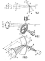
- Figure 1 is a schematic representation of a known image pickup device.
- Figure 2 is a partly schematic, partly perspective view of an embodiment of an image pickup device according to the invention.
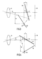
- Figure 3 is a schematic view of a portion of the image pickup device according to the invention with the mirror annulus at a first rotational position.
- Figure 4 is a schematic view of a portion of the image pickup device according to the invention with the mirror annulus at a second rotational position.
- Figure 5 is a perspective view of another embodiment of the image pickup device according to the invention.
- FIG. 2 shows an embodiment of an image pickup device according to the invention.
- the image pickup device includes a lens means 24, a mirror annulus 26, a detector means 28, and a means 30 for rotating the mirror annulus.
- the lens means 24 is arranged to receive light rays 32 from a distant scene (that is, a scene located well beyond the focal distance of the lens means 24). From these light rays, lens means 24 forms an image of the scene in an image surface.
- the lens means 24 has an optical axis 34.
- the lens means 24 may be one or more optical components for forming a real image of a scene.
- lens means 24 may be a conventional objective lens.
- lens means 24 is an anamorphic lens.
- An anamorphic lens is a lens having different focal lengths in different planes, for example focal length A in the horizontal plane and focal length B in the vertical plane.
- the anamorphic lens 24 forms the ray bundle onto a narrow line on the mirror annulus 26 in order to minimize the difference in the tilt angle from one side of the ray bundle to the other.
- a second anamorphic lens 25 is provided between the mirror 26 and the detector means 28, in order to reconstruct the image of the scene on the detector means.
- the mirror annulus 26 is arranged behind the lens means 24.
- Mirror annulys 26 is rotatable about an axis of rotation 36 so that the light rays 32 pass sequentially across the entire reflecting surface 38 of the mirror annulys 26 as the mirror annulus is rotated.
- the detector means 28 comprises, for example, a linear aaray 40 of individual detector elements.
- the array 40 is oriented so that its projection onto optical axis 34 is perpendicular to optical axis 34.
- the detector elements in array 40 may be any conventional light detectors.
- the reflecting surface 38 of the mirror annulus 26 is arranged at a tilt angle about the circumferential axis 42 of the mirror annulus 26. As shown in Figure 2, the tilt angle of the reflecting surface 38 varies as a function of the position of the reflecting surface 38 along the circumferential axis 42. (A gap is shown between the ends of annulus 26 to clearly show the changing tilt angle. In practice, however, this gap would not be present.)
- the means 30 for rotating the mirror annulus 26 causes the mirror annulus 26 to spin on its axis of rotation 36.
- the mirror annulus 26 and the axis of rotation 36 are arranged such that the circumferential axis 42 always intersects the optical axis 34 through the entire rotation of the mirror annulus 26.
- each segment of the reflecting surface 38 which presents itself at the optical axis 34 appears at a different tilt angle. Rotation of the mirror annulus 26 thus approximates the rocking motion of the scan mirror 14 in the prior art arrangement shown in Figure 1.
- the detector means 28 In order to scan a sharp image across the detector means 28, the detector means 28 must be arranged at the focal surface of the lens means 24. Figures 3 and 4 show how this is achieved in one embodiment of the present invention.
- Figure 3 schematically shows a cross-section through a part of the image pickup device of Figure 2.
- the mirror annulus is at a first rotational position such that the mirror segment 44 of the reflecting surface 38 subtends a tilt angle ⁇ , around the circumferential axis 42.
- the tilt angle, ⁇ is measured with respect to the optical axis 34, and in Figure 3 it is between 45 o and 90 o .
- the detector means 28, in this embodiment of the invention, is arranged in a plane 46 which is perpendicular to the optical axis 34.
- the perpendicular distance between the detector means 28 and the optical axis 34 is Y d .
- the lens means 24 In the absence of the mirror annulus 26, the lens means 24 would form an image of the scene at image surface 48.
- the distance between the image surface 48 and the detector plane 46 measured along the optical axis is selected to be equal to the distance, Y d , between the optical axis 34 and the light-sensitive surface of the detector means 28.
- the distance, x, between the circumferential axis 42 and the detector plane 46 must be varied according a complicated form which expresses x as a function of Y d , ⁇ and the focal distance of the lens.
- the expression relating x, Y d , ⁇ and the focal distance can be approximated by the following formula:
- the distance x is 0.
- the circumferential axis 42 then intersects both the optical axis 34 and the detector plane 46.
- a numerical computer may be used to determine the distance x for any given tilt angle ⁇ .
- the limits on the tilt angle are determined by considerations such as field width, angular sensitivity of the detector means and construction of the embodiment. In practice, the tilt angle need only range from 30 o to 60 o .
- Mirror annulus 26 may be manufactured, for example, by starting with a thick aluminium ring.
- the ring can be machined roughly into the desired shape of annulus 26, after which the precise shape can be produced on a numerically-controlled cutter. If the annulus is to be used to reflect infrared in the 3 to 5 or 8 to 12 micron regions, small imperfections in its surface will not degrade the image quality. If shorter wavelengths are to be used, the aluminum surface can be hand polished after it is cut.
- mirror annulus produced in the manner described above can be used in a scanner, preferably it is used as a master to produce other mirrors.
- a negative mold can be produced from the master. Then further mirror annulli can be produced from the negative mold.
- each aluminum mirror annulus is provided with a conventional overcoat to prevent oxidation and to maintain a highly reflective surface.
- Figures 2, 3 and 4 show only one embodiment of the present invention.
- the detector means 28 be arranged in a plane which is perpendicular to the optical axis 34.
- the detector plane 46 could be arranged at any angle with respect to the optical axis 34, and then the equations for the location of the circumferential axis 42 can be derived accordingly.
- the mirror annulus is represented with the reflecting surface substantial perpendicular to the axis of rotation.
- the reflecting surface may be substantial parallel to the rotation axis, or have any other angle convenient to the embodiment.
- the mirror annulus produces two complete scans of the scene for each complete rotation.
- Each half of the mirror annulus produces a complete scan.
- the two halves are in slightly nonparallel planes in order to provide interlace.
Landscapes
- Physics & Mathematics (AREA)
- Health & Medical Sciences (AREA)
- Electromagnetism (AREA)
- Toxicology (AREA)
- Engineering & Computer Science (AREA)
- Multimedia (AREA)
- Signal Processing (AREA)
- Mechanical Optical Scanning Systems (AREA)
- Stereoscopic And Panoramic Photography (AREA)
- Transforming Light Signals Into Electric Signals (AREA)
Claims (6)
- Bildaufnahmegerät mit
einem Linsensystem (24) zum Empfangen von Licht einer Szene und zum Bilden einer Abbildung der Szene in einer Bildebene, wobei das Linsensystem eine optische Achse (34) aufweist,
einem bewegbaren Reflektor, der hinter das Linsensystem zum Reflektieren des Lichts von der Szene das durch das Linsenmittel fällt, angeordnet ist, wobei die Abbildung in einer Richtung bewogen wird,
einem Detektor (28) zum Empfangen von Licht von der Szene, das vom Reflektor zurückgeworfen wird, dadurch gekennzeichnet, daß
der bewegbaren Reflektor ein verdrillter reflektierender Kreisring (26) ist, der um eine Drehachse (36) senkrecht zur mittleren Kreisringebene drehbar ist,
der reflektierenden Kreisring eine Umfangsachse (42) besitzt, die die optische Achse (34) während die ganze Drehung des reflektierenden Kreisrings schneidet,
die reflektierende Fläche (38) des Kreisrings unter einem Neigungswinkel (Φ)in bezug auf die Umfangsachse angebracht ist, wobei der Neigungswinkel der reflektierenden Fläche abhängig von der Lage der reflektierenden Fläche entlang der Umfangsachse (42) schwankt, und
die Umfangsachse (42) auf der optischen Achse (34) im Abstand vom Linsensystem (24) angebracht ist, wobei der Abstand in Abhängigkeit vom Neigungswinkel der Umfangsfläche derart schwankt, daß das Bild immer auf den Detektor (28) fokussiert ist. - Bildaufnahmegerät nach Anspruch 1, dadurch gekennzeichnet, daß
der Detektor (28) sich in einer Ebene senkrecht zur optischen Achse (34) befindet,
und der Abstand (Yd) vom Detektor (28) zur optischen Achse (34) gleich dem Brennpunktsabstand des Linsensystems weniger dem Abstand zwischen dem Linsensystem und der Ebene ist. - Bildaufnahmegerät nach Anspruch 2, dadurch gekennzeichnet, daß die gesamte Feldbreite nicht mehr als 30o beträgt, und daß der Abstand x der Umfangsachse (42) zur Detektorebene vom Neigungswinkel Φ entsprechend folgender Gleichung abhängig ist:

- Bildaufnahmegerät nach Anspruch 3, dadurch gekennzeichnet, daß das Linsensystem (24) eine herkömmliche Objektivlinse ist.
- Bildaufnahmegerät nach Anspruch 3, dadurch gekennzeichnet, daß das Linsensystem (24) eine anamorphische Linse ist.
- Bildaufnahmegerät nach Anspruch 4 oder 5, dadurch gekennzeichnet, daß das Gerät weiter noch Mittel (30) zum Drehen des verdrillten reflektierenden Kreisrings auf der Drehachse (36) enthält.
Applications Claiming Priority (2)
| Application Number | Priority Date | Filing Date | Title |
|---|---|---|---|
| US684200 | 1984-12-20 | ||
| US06/684,200 US4641192A (en) | 1984-12-20 | 1984-12-20 | Focus-corrected convergent beam scanner |
Publications (3)
| Publication Number | Publication Date |
|---|---|
| EP0186920A2 EP0186920A2 (de) | 1986-07-09 |
| EP0186920A3 EP0186920A3 (en) | 1988-01-07 |
| EP0186920B1 true EP0186920B1 (de) | 1991-10-16 |
Family
ID=24747073
Family Applications (1)
| Application Number | Title | Priority Date | Filing Date |
|---|---|---|---|
| EP85201945A Expired EP0186920B1 (de) | 1984-12-20 | 1985-11-25 | Brennpunktkorrigiertes Konvergentstrahlabtasteinrichtung |
Country Status (4)
| Country | Link |
|---|---|
| US (1) | US4641192A (de) |
| EP (1) | EP0186920B1 (de) |
| JP (1) | JPS61151606A (de) |
| DE (1) | DE3584438D1 (de) |
Cited By (1)
| Publication number | Priority date | Publication date | Assignee | Title |
|---|---|---|---|---|
| DE102013108066A1 (de) * | 2013-07-29 | 2015-01-29 | Limo Patentverwaltung Gmbh & Co. Kg | Vorrichtung zur Ablenkung eines Lichtstrahls |
Families Citing this family (2)
| Publication number | Priority date | Publication date | Assignee | Title |
|---|---|---|---|---|
| GB2256937A (en) * | 1991-06-21 | 1992-12-23 | Gec Ferranti Defence Syst | Optical scanner |
| US5398082A (en) * | 1993-05-20 | 1995-03-14 | Hughes-Jvc Technology Corporation | Scanned illumination for light valve video projectors |
Family Cites Families (10)
| Publication number | Priority date | Publication date | Assignee | Title |
|---|---|---|---|---|
| US1787920A (en) * | 1929-03-07 | 1931-01-06 | Arthur H Watson | Television apparatus |
| GB374564A (en) * | 1931-04-09 | 1932-06-16 | John Logie Baird | Improvements in or relating to scanning apparatus for use in television and like systems |
| DE591731C (de) * | 1931-04-15 | 1934-01-26 | I M K Syndicate Ltd | Verfahren zur Bildzerlegung und -zusammensetzung beim Fernsehen |
| US3626091A (en) * | 1969-12-11 | 1971-12-07 | Hughes Aircraft Co | Image converter |
| GB1569879A (en) * | 1975-12-13 | 1980-06-25 | Barr & Stroud Ltd | Radiation scanning system |
| JPS54143240A (en) * | 1978-04-28 | 1979-11-08 | Jeol Ltd | Scanning optical system of thermography apparatus |
| GB2087189B (en) * | 1980-11-10 | 1984-08-01 | Philips Electronic Associated | Imaging apparatus |
| JPS57129430A (en) * | 1981-02-04 | 1982-08-11 | Mitsubishi Electric Corp | Infrared-ray image pickup device |
| DE3133641A1 (de) * | 1981-08-26 | 1983-03-10 | Philips Patentverwaltung Gmbh, 2000 Hamburg | Ir-sichtgeraet |
| DE4006635A1 (de) * | 1990-03-03 | 1991-09-05 | Georg Binnen | Schleppdueseneinrichtung fuer schnellaufende bogenanleger |
-
1984
- 1984-12-20 US US06/684,200 patent/US4641192A/en not_active Expired - Lifetime
-
1985
- 1985-11-25 EP EP85201945A patent/EP0186920B1/de not_active Expired
- 1985-11-25 DE DE8585201945T patent/DE3584438D1/de not_active Expired - Lifetime
- 1985-12-17 JP JP60282126A patent/JPS61151606A/ja active Pending
Cited By (1)
| Publication number | Priority date | Publication date | Assignee | Title |
|---|---|---|---|---|
| DE102013108066A1 (de) * | 2013-07-29 | 2015-01-29 | Limo Patentverwaltung Gmbh & Co. Kg | Vorrichtung zur Ablenkung eines Lichtstrahls |
Also Published As
| Publication number | Publication date |
|---|---|
| US4641192A (en) | 1987-02-03 |
| EP0186920A3 (en) | 1988-01-07 |
| JPS61151606A (ja) | 1986-07-10 |
| DE3584438D1 (de) | 1991-11-21 |
| EP0186920A2 (de) | 1986-07-09 |
Similar Documents
| Publication | Publication Date | Title |
|---|---|---|
| US4923263A (en) | Rotating mirror optical scanning device | |
| EP0299964B1 (de) | Abtastvorrichtung | |
| US4123135A (en) | Optical system for rotating mirror line scanning apparatus | |
| US4525749A (en) | Method and apparatus for scanning an object by using the light | |
| JPH0450563B2 (de) | ||
| US3973826A (en) | Scanning devices | |
| US4312590A (en) | Optical scanner and system for laser beam exposure of photo surfaces | |
| EP0710864B1 (de) | Lichtstrahlaufzeichnungsgerät mit Änderung der optischen Weglänge | |
| US4650997A (en) | Infrared target image system employing rotating polygonal mirror | |
| US3972583A (en) | Scanning devices | |
| GB2115174A (en) | Optical scanning systems | |
| EP0186920B1 (de) | Brennpunktkorrigiertes Konvergentstrahlabtasteinrichtung | |
| EP0112374B1 (de) | Optische abtasteinrichtung | |
| US3845298A (en) | Optical scanning device | |
| JPH01149010A (ja) | 回転ミラー走査装置 | |
| US3619039A (en) | Laser scanning system including rotating reflector | |
| US3802759A (en) | Device for optical-mechanical scanning of images by means of corner reflectors | |
| US4912321A (en) | Radiation scanning system with pupil control | |
| US3497298A (en) | Optical scanning method for copying machines | |
| EP0209929B1 (de) | Optische Abtastvorrichtung | |
| US5173603A (en) | Focus changing apparatus and method for optical scanners | |
| US5239404A (en) | Large angle reflective scanning system and method | |
| HK19090A (en) | Optical scanning apparatus including polygonal scanning mirror assembly | |
| US4516159A (en) | Elevation step scanner | |
| EP0347030A2 (de) | Abtastvorrichtung und -verfahren |
Legal Events
| Date | Code | Title | Description |
|---|---|---|---|
| PUAI | Public reference made under article 153(3) epc to a published international application that has entered the european phase |
Free format text: ORIGINAL CODE: 0009012 |
|
| AK | Designated contracting states |
Kind code of ref document: A2 Designated state(s): DE FR GB NL SE |
|
| PUAL | Search report despatched |
Free format text: ORIGINAL CODE: 0009013 |
|
| AK | Designated contracting states |
Kind code of ref document: A3 Designated state(s): DE FR GB NL SE |
|
| 17P | Request for examination filed |
Effective date: 19880706 |
|
| 17Q | First examination report despatched |
Effective date: 19900625 |
|
| GRAA | (expected) grant |
Free format text: ORIGINAL CODE: 0009210 |
|
| AK | Designated contracting states |
Kind code of ref document: B1 Designated state(s): DE FR GB NL SE |
|
| REF | Corresponds to: |
Ref document number: 3584438 Country of ref document: DE Date of ref document: 19911121 |
|
| ET | Fr: translation filed | ||
| PLBE | No opposition filed within time limit |
Free format text: ORIGINAL CODE: 0009261 |
|
| STAA | Information on the status of an ep patent application or granted ep patent |
Free format text: STATUS: NO OPPOSITION FILED WITHIN TIME LIMIT |
|
| 26N | No opposition filed | ||
| REG | Reference to a national code |
Ref country code: FR Ref legal event code: CD |
|
| NLT1 | Nl: modifications of names registered in virtue of documents presented to the patent office pursuant to art. 16 a, paragraph 1 |
Owner name: MAGNAVOX ELECTRONIC SYSTEMS COMPANY TE FORT WAYNE, |
|
| PGFP | Annual fee paid to national office [announced via postgrant information from national office to epo] |
Ref country code: GB Payment date: 19941031 Year of fee payment: 10 |
|
| PGFP | Annual fee paid to national office [announced via postgrant information from national office to epo] |
Ref country code: SE Payment date: 19941124 Year of fee payment: 10 |
|
| PGFP | Annual fee paid to national office [announced via postgrant information from national office to epo] |
Ref country code: FR Payment date: 19941125 Year of fee payment: 10 |
|
| PGFP | Annual fee paid to national office [announced via postgrant information from national office to epo] |
Ref country code: NL Payment date: 19941130 Year of fee payment: 10 |
|
| PGFP | Annual fee paid to national office [announced via postgrant information from national office to epo] |
Ref country code: DE Payment date: 19950124 Year of fee payment: 10 |
|
| EAL | Se: european patent in force in sweden |
Ref document number: 85201945.4 |
|
| PG25 | Lapsed in a contracting state [announced via postgrant information from national office to epo] |
Ref country code: GB Effective date: 19951125 |
|
| PG25 | Lapsed in a contracting state [announced via postgrant information from national office to epo] |
Ref country code: SE Effective date: 19951126 |
|
| PG25 | Lapsed in a contracting state [announced via postgrant information from national office to epo] |
Ref country code: NL Effective date: 19960601 |
|
| GBPC | Gb: european patent ceased through non-payment of renewal fee |
Effective date: 19951125 |
|
| PG25 | Lapsed in a contracting state [announced via postgrant information from national office to epo] |
Ref country code: FR Effective date: 19960731 |
|
| NLV4 | Nl: lapsed or anulled due to non-payment of the annual fee |
Effective date: 19960601 |
|
| PG25 | Lapsed in a contracting state [announced via postgrant information from national office to epo] |
Ref country code: DE Effective date: 19960801 |
|
| EUG | Se: european patent has lapsed |
Ref document number: 85201945.4 |
|
| REG | Reference to a national code |
Ref country code: FR Ref legal event code: ST |