EP0186867A2 - Coffee or tea filter pouch and process of producing it - Google Patents
Coffee or tea filter pouch and process of producing it Download PDFInfo
- Publication number
- EP0186867A2 EP0186867A2 EP85116268A EP85116268A EP0186867A2 EP 0186867 A2 EP0186867 A2 EP 0186867A2 EP 85116268 A EP85116268 A EP 85116268A EP 85116268 A EP85116268 A EP 85116268A EP 0186867 A2 EP0186867 A2 EP 0186867A2
- Authority
- EP
- European Patent Office
- Prior art keywords
- filter
- pouch
- coffee
- heatsealing
- filter pouch
- Prior art date
- Legal status (The legal status is an assumption and is not a legal conclusion. Google has not performed a legal analysis and makes no representation as to the accuracy of the status listed.)
- Withdrawn
Links
- 235000013353 coffee beverage Nutrition 0.000 title claims abstract description 62
- 235000016213 coffee Nutrition 0.000 title claims abstract description 61
- 238000000034 method Methods 0.000 title claims abstract description 28
- 241001122767 Theaceae Species 0.000 title claims abstract description 20
- 239000000463 material Substances 0.000 claims abstract description 43
- 239000000843 powder Substances 0.000 claims abstract description 32
- 238000007789 sealing Methods 0.000 claims abstract description 25
- 238000004519 manufacturing process Methods 0.000 claims abstract description 20
- 238000005520 cutting process Methods 0.000 claims description 22
- QNRATNLHPGXHMA-XZHTYLCXSA-N (r)-(6-ethoxyquinolin-4-yl)-[(2s,4s,5r)-5-ethyl-1-azabicyclo[2.2.2]octan-2-yl]methanol;hydrochloride Chemical compound Cl.C([C@H]([C@H](C1)CC)C2)CN1[C@@H]2[C@H](O)C1=CC=NC2=CC=C(OCC)C=C21 QNRATNLHPGXHMA-XZHTYLCXSA-N 0.000 claims description 6
- 230000003247 decreasing effect Effects 0.000 claims 1
- XLYOFNOQVPJJNP-UHFFFAOYSA-N water Substances O XLYOFNOQVPJJNP-UHFFFAOYSA-N 0.000 description 14
- 235000013616 tea Nutrition 0.000 description 8
- 238000009835 boiling Methods 0.000 description 5
- 239000000835 fiber Substances 0.000 description 4
- 238000001914 filtration Methods 0.000 description 4
- 238000003780 insertion Methods 0.000 description 3
- 230000037431 insertion Effects 0.000 description 3
- 238000010924 continuous production Methods 0.000 description 2
- 230000000149 penetrating effect Effects 0.000 description 2
- 229920002994 synthetic fiber Polymers 0.000 description 2
- 238000003466 welding Methods 0.000 description 2
- 235000004522 Pentaglottis sempervirens Nutrition 0.000 description 1
- 238000009825 accumulation Methods 0.000 description 1
- 238000004026 adhesive bonding Methods 0.000 description 1
- 125000003118 aryl group Chemical group 0.000 description 1
- 235000013361 beverage Nutrition 0.000 description 1
- 230000001143 conditioned effect Effects 0.000 description 1
- 230000001419 dependent effect Effects 0.000 description 1
- 238000013461 design Methods 0.000 description 1
- 238000010586 diagram Methods 0.000 description 1
- 235000013305 food Nutrition 0.000 description 1
- 238000005259 measurement Methods 0.000 description 1
- 238000012986 modification Methods 0.000 description 1
- 230000004048 modification Effects 0.000 description 1
- 230000007935 neutral effect Effects 0.000 description 1
- 238000004806 packaging method and process Methods 0.000 description 1
- 230000002028 premature Effects 0.000 description 1
- 238000002360 preparation method Methods 0.000 description 1
- 238000000926 separation method Methods 0.000 description 1
- 239000000126 substance Substances 0.000 description 1
- 230000008961 swelling Effects 0.000 description 1
- 239000012209 synthetic fiber Substances 0.000 description 1
- 229920002397 thermoplastic olefin Polymers 0.000 description 1
- 239000002699 waste material Substances 0.000 description 1
- 238000009736 wetting Methods 0.000 description 1
Images


Classifications
-
- B—PERFORMING OPERATIONS; TRANSPORTING
- B29—WORKING OF PLASTICS; WORKING OF SUBSTANCES IN A PLASTIC STATE IN GENERAL
- B29C—SHAPING OR JOINING OF PLASTICS; SHAPING OF MATERIAL IN A PLASTIC STATE, NOT OTHERWISE PROVIDED FOR; AFTER-TREATMENT OF THE SHAPED PRODUCTS, e.g. REPAIRING
- B29C66/00—General aspects of processes or apparatus for joining preformed parts
- B29C66/80—General aspects of machine operations or constructions and parts thereof
- B29C66/83—General aspects of machine operations or constructions and parts thereof characterised by the movement of the joining or pressing tools
- B29C66/834—General aspects of machine operations or constructions and parts thereof characterised by the movement of the joining or pressing tools moving with the parts to be joined
- B29C66/8351—Jaws mounted on rollers, cylinders, drums, bands, belts or chains; Flying jaws
- B29C66/83511—Jaws mounted on rollers, cylinders, drums, bands, belts or chains; Flying jaws jaws mounted on rollers, cylinders or drums
-
- B—PERFORMING OPERATIONS; TRANSPORTING
- B29—WORKING OF PLASTICS; WORKING OF SUBSTANCES IN A PLASTIC STATE IN GENERAL
- B29C—SHAPING OR JOINING OF PLASTICS; SHAPING OF MATERIAL IN A PLASTIC STATE, NOT OTHERWISE PROVIDED FOR; AFTER-TREATMENT OF THE SHAPED PRODUCTS, e.g. REPAIRING
- B29C65/00—Joining or sealing of preformed parts, e.g. welding of plastics materials; Apparatus therefor
- B29C65/02—Joining or sealing of preformed parts, e.g. welding of plastics materials; Apparatus therefor by heating, with or without pressure
-
- B—PERFORMING OPERATIONS; TRANSPORTING
- B29—WORKING OF PLASTICS; WORKING OF SUBSTANCES IN A PLASTIC STATE IN GENERAL
- B29C—SHAPING OR JOINING OF PLASTICS; SHAPING OF MATERIAL IN A PLASTIC STATE, NOT OTHERWISE PROVIDED FOR; AFTER-TREATMENT OF THE SHAPED PRODUCTS, e.g. REPAIRING
- B29C66/00—General aspects of processes or apparatus for joining preformed parts
- B29C66/01—General aspects dealing with the joint area or with the area to be joined
- B29C66/05—Particular design of joint configurations
- B29C66/10—Particular design of joint configurations particular design of the joint cross-sections
- B29C66/11—Joint cross-sections comprising a single joint-segment, i.e. one of the parts to be joined comprising a single joint-segment in the joint cross-section
- B29C66/112—Single lapped joints
- B29C66/1122—Single lap to lap joints, i.e. overlap joints
-
- B—PERFORMING OPERATIONS; TRANSPORTING
- B29—WORKING OF PLASTICS; WORKING OF SUBSTANCES IN A PLASTIC STATE IN GENERAL
- B29C—SHAPING OR JOINING OF PLASTICS; SHAPING OF MATERIAL IN A PLASTIC STATE, NOT OTHERWISE PROVIDED FOR; AFTER-TREATMENT OF THE SHAPED PRODUCTS, e.g. REPAIRING
- B29C66/00—General aspects of processes or apparatus for joining preformed parts
- B29C66/40—General aspects of joining substantially flat articles, e.g. plates, sheets or web-like materials; Making flat seams in tubular or hollow articles; Joining single elements to substantially flat surfaces
- B29C66/41—Joining substantially flat articles ; Making flat seams in tubular or hollow articles
- B29C66/43—Joining a relatively small portion of the surface of said articles
- B29C66/431—Joining the articles to themselves
- B29C66/4312—Joining the articles to themselves for making flat seams in tubular or hollow articles, e.g. transversal seams
- B29C66/43121—Closing the ends of tubular or hollow single articles, e.g. closing the ends of bags
-
- B—PERFORMING OPERATIONS; TRANSPORTING
- B29—WORKING OF PLASTICS; WORKING OF SUBSTANCES IN A PLASTIC STATE IN GENERAL
- B29C—SHAPING OR JOINING OF PLASTICS; SHAPING OF MATERIAL IN A PLASTIC STATE, NOT OTHERWISE PROVIDED FOR; AFTER-TREATMENT OF THE SHAPED PRODUCTS, e.g. REPAIRING
- B29C66/00—General aspects of processes or apparatus for joining preformed parts
- B29C66/40—General aspects of joining substantially flat articles, e.g. plates, sheets or web-like materials; Making flat seams in tubular or hollow articles; Joining single elements to substantially flat surfaces
- B29C66/41—Joining substantially flat articles ; Making flat seams in tubular or hollow articles
- B29C66/43—Joining a relatively small portion of the surface of said articles
- B29C66/433—Casing-in, i.e. enclosing an element between two sheets by an outlined seam
-
- B—PERFORMING OPERATIONS; TRANSPORTING
- B29—WORKING OF PLASTICS; WORKING OF SUBSTANCES IN A PLASTIC STATE IN GENERAL
- B29C—SHAPING OR JOINING OF PLASTICS; SHAPING OF MATERIAL IN A PLASTIC STATE, NOT OTHERWISE PROVIDED FOR; AFTER-TREATMENT OF THE SHAPED PRODUCTS, e.g. REPAIRING
- B29C66/00—General aspects of processes or apparatus for joining preformed parts
- B29C66/80—General aspects of machine operations or constructions and parts thereof
- B29C66/81—General aspects of the pressing elements, i.e. the elements applying pressure on the parts to be joined in the area to be joined, e.g. the welding jaws or clamps
- B29C66/814—General aspects of the pressing elements, i.e. the elements applying pressure on the parts to be joined in the area to be joined, e.g. the welding jaws or clamps characterised by the design of the pressing elements, e.g. of the welding jaws or clamps
- B29C66/8141—General aspects of the pressing elements, i.e. the elements applying pressure on the parts to be joined in the area to be joined, e.g. the welding jaws or clamps characterised by the design of the pressing elements, e.g. of the welding jaws or clamps characterised by the surface geometry of the part of the pressing elements, e.g. welding jaws or clamps, coming into contact with the parts to be joined
- B29C66/81433—General aspects of the pressing elements, i.e. the elements applying pressure on the parts to be joined in the area to be joined, e.g. the welding jaws or clamps characterised by the design of the pressing elements, e.g. of the welding jaws or clamps characterised by the surface geometry of the part of the pressing elements, e.g. welding jaws or clamps, coming into contact with the parts to be joined being toothed, i.e. comprising several teeth or pins, or being patterned
-
- B—PERFORMING OPERATIONS; TRANSPORTING
- B29—WORKING OF PLASTICS; WORKING OF SUBSTANCES IN A PLASTIC STATE IN GENERAL
- B29C—SHAPING OR JOINING OF PLASTICS; SHAPING OF MATERIAL IN A PLASTIC STATE, NOT OTHERWISE PROVIDED FOR; AFTER-TREATMENT OF THE SHAPED PRODUCTS, e.g. REPAIRING
- B29C66/00—General aspects of processes or apparatus for joining preformed parts
- B29C66/80—General aspects of machine operations or constructions and parts thereof
- B29C66/84—Specific machine types or machines suitable for specific applications
- B29C66/849—Packaging machines
-
- B—PERFORMING OPERATIONS; TRANSPORTING
- B65—CONVEYING; PACKING; STORING; HANDLING THIN OR FILAMENTARY MATERIAL
- B65B—MACHINES, APPARATUS OR DEVICES FOR, OR METHODS OF, PACKAGING ARTICLES OR MATERIALS; UNPACKING
- B65B9/00—Enclosing successive articles, or quantities of material, e.g. liquids or semiliquids, in flat, folded, or tubular webs of flexible sheet material; Subdividing filled flexible tubes to form packages
- B65B9/02—Enclosing successive articles, or quantities of material between opposed webs
- B65B9/023—Packaging fluent material
-
- B—PERFORMING OPERATIONS; TRANSPORTING
- B65—CONVEYING; PACKING; STORING; HANDLING THIN OR FILAMENTARY MATERIAL
- B65B—MACHINES, APPARATUS OR DEVICES FOR, OR METHODS OF, PACKAGING ARTICLES OR MATERIALS; UNPACKING
- B65B9/00—Enclosing successive articles, or quantities of material, e.g. liquids or semiliquids, in flat, folded, or tubular webs of flexible sheet material; Subdividing filled flexible tubes to form packages
- B65B9/06—Enclosing successive articles, or quantities of material, in a longitudinally-folded web, or in a web folded into a tube about the articles or quantities of material placed upon it
- B65B9/08—Enclosing successive articles, or quantities of material, in a longitudinally-folded web, or in a web folded into a tube about the articles or quantities of material placed upon it in a web folded and sealed transversely to form pockets which are subsequently filled and then closed by sealing
- B65B9/093—Enclosing successive articles, or quantities of material, in a longitudinally-folded web, or in a web folded into a tube about the articles or quantities of material placed upon it in a web folded and sealed transversely to form pockets which are subsequently filled and then closed by sealing the web having intermittent motion
-
- B—PERFORMING OPERATIONS; TRANSPORTING
- B65—CONVEYING; PACKING; STORING; HANDLING THIN OR FILAMENTARY MATERIAL
- B65D—CONTAINERS FOR STORAGE OR TRANSPORT OF ARTICLES OR MATERIALS, e.g. BAGS, BARRELS, BOTTLES, BOXES, CANS, CARTONS, CRATES, DRUMS, JARS, TANKS, HOPPERS, FORWARDING CONTAINERS; ACCESSORIES, CLOSURES, OR FITTINGS THEREFOR; PACKAGING ELEMENTS; PACKAGES
- B65D85/00—Containers, packaging elements or packages, specially adapted for particular articles or materials
- B65D85/70—Containers, packaging elements or packages, specially adapted for particular articles or materials for materials not otherwise provided for
- B65D85/804—Disposable containers or packages with contents which are mixed, infused or dissolved in situ, i.e. without having been previously removed from the package
- B65D85/8043—Packages adapted to allow liquid to pass through the contents
- B65D85/8061—Filters
-
- B—PERFORMING OPERATIONS; TRANSPORTING
- B29—WORKING OF PLASTICS; WORKING OF SUBSTANCES IN A PLASTIC STATE IN GENERAL
- B29C—SHAPING OR JOINING OF PLASTICS; SHAPING OF MATERIAL IN A PLASTIC STATE, NOT OTHERWISE PROVIDED FOR; AFTER-TREATMENT OF THE SHAPED PRODUCTS, e.g. REPAIRING
- B29C65/00—Joining or sealing of preformed parts, e.g. welding of plastics materials; Apparatus therefor
- B29C65/02—Joining or sealing of preformed parts, e.g. welding of plastics materials; Apparatus therefor by heating, with or without pressure
- B29C65/18—Joining or sealing of preformed parts, e.g. welding of plastics materials; Apparatus therefor by heating, with or without pressure using heated tools
-
- B—PERFORMING OPERATIONS; TRANSPORTING
- B29—WORKING OF PLASTICS; WORKING OF SUBSTANCES IN A PLASTIC STATE IN GENERAL
- B29C—SHAPING OR JOINING OF PLASTICS; SHAPING OF MATERIAL IN A PLASTIC STATE, NOT OTHERWISE PROVIDED FOR; AFTER-TREATMENT OF THE SHAPED PRODUCTS, e.g. REPAIRING
- B29C66/00—General aspects of processes or apparatus for joining preformed parts
- B29C66/80—General aspects of machine operations or constructions and parts thereof
- B29C66/83—General aspects of machine operations or constructions and parts thereof characterised by the movement of the joining or pressing tools
- B29C66/832—Reciprocating joining or pressing tools
- B29C66/8322—Joining or pressing tools reciprocating along one axis
-
- B—PERFORMING OPERATIONS; TRANSPORTING
- B29—WORKING OF PLASTICS; WORKING OF SUBSTANCES IN A PLASTIC STATE IN GENERAL
- B29C—SHAPING OR JOINING OF PLASTICS; SHAPING OF MATERIAL IN A PLASTIC STATE, NOT OTHERWISE PROVIDED FOR; AFTER-TREATMENT OF THE SHAPED PRODUCTS, e.g. REPAIRING
- B29C66/00—General aspects of processes or apparatus for joining preformed parts
- B29C66/80—General aspects of machine operations or constructions and parts thereof
- B29C66/83—General aspects of machine operations or constructions and parts thereof characterised by the movement of the joining or pressing tools
- B29C66/834—General aspects of machine operations or constructions and parts thereof characterised by the movement of the joining or pressing tools moving with the parts to be joined
- B29C66/8341—Roller, cylinder or drum types; Band or belt types; Ball types
- B29C66/83411—Roller, cylinder or drum types
-
- B—PERFORMING OPERATIONS; TRANSPORTING
- B29—WORKING OF PLASTICS; WORKING OF SUBSTANCES IN A PLASTIC STATE IN GENERAL
- B29C—SHAPING OR JOINING OF PLASTICS; SHAPING OF MATERIAL IN A PLASTIC STATE, NOT OTHERWISE PROVIDED FOR; AFTER-TREATMENT OF THE SHAPED PRODUCTS, e.g. REPAIRING
- B29C66/00—General aspects of processes or apparatus for joining preformed parts
- B29C66/80—General aspects of machine operations or constructions and parts thereof
- B29C66/83—General aspects of machine operations or constructions and parts thereof characterised by the movement of the joining or pressing tools
- B29C66/834—General aspects of machine operations or constructions and parts thereof characterised by the movement of the joining or pressing tools moving with the parts to be joined
- B29C66/8351—Jaws mounted on rollers, cylinders, drums, bands, belts or chains; Flying jaws
- B29C66/83511—Jaws mounted on rollers, cylinders, drums, bands, belts or chains; Flying jaws jaws mounted on rollers, cylinders or drums
- B29C66/83513—Jaws mounted on rollers, cylinders, drums, bands, belts or chains; Flying jaws jaws mounted on rollers, cylinders or drums cooperating jaws mounted on rollers, cylinders or drums and moving in a closed path
-
- B—PERFORMING OPERATIONS; TRANSPORTING
- B29—WORKING OF PLASTICS; WORKING OF SUBSTANCES IN A PLASTIC STATE IN GENERAL
- B29K—INDEXING SCHEME ASSOCIATED WITH SUBCLASSES B29B, B29C OR B29D, RELATING TO MOULDING MATERIALS OR TO MATERIALS FOR MOULDS, REINFORCEMENTS, FILLERS OR PREFORMED PARTS, e.g. INSERTS
- B29K2711/00—Use of natural products or their composites, not provided for in groups B29K2601/00 - B29K2709/00, for preformed parts, e.g. for inserts
- B29K2711/12—Paper, e.g. cardboard
- B29K2711/126—Impregnated
-
- B—PERFORMING OPERATIONS; TRANSPORTING
- B29—WORKING OF PLASTICS; WORKING OF SUBSTANCES IN A PLASTIC STATE IN GENERAL
- B29L—INDEXING SCHEME ASSOCIATED WITH SUBCLASS B29C, RELATING TO PARTICULAR ARTICLES
- B29L2031/00—Other particular articles
- B29L2031/14—Filters
-
- B—PERFORMING OPERATIONS; TRANSPORTING
- B29—WORKING OF PLASTICS; WORKING OF SUBSTANCES IN A PLASTIC STATE IN GENERAL
- B29L—INDEXING SCHEME ASSOCIATED WITH SUBCLASS B29C, RELATING TO PARTICULAR ARTICLES
- B29L2031/00—Other particular articles
- B29L2031/712—Containers; Packaging elements or accessories, Packages
- B29L2031/7122—Tea bags
Definitions
- the invention relates to a conical coffee or tea filter pouch to produce filtered coffee or, resp., tea by means of brewing coffee powder or, resp. tea leaves with boiling water.
- the filter pouch has two layers of a water-permeable filter material, which are joined at the edges to form a package receiving the coffee powder or, resp., the tea leaves.
- the circular-segment-configured shape of the filter pouch makes it particularly suited for insertion into the commercially customary conical filter holding cones on coffee machines or coffee pots. Furthermore, it is suited in particular for producing amounts of coffee for several cups.
- the invention relates, furthermore, to a process for producing the coffee-filter pouch in a continuous production operation.
- Coffee-filtering pouches of two layers of paper or other water-permeable filter material are known from the DE-Al-22 18 081 and 27 38 969.
- the layers are joined at their edges through mechanical pressure, through adhesive bonding or through welding.
- the other edges are folded.
- the coffee pouch according to DE-A1 27 38 969 is used similarly as a tea bag to produce individual portions of coffee and is, for that purpose, hung into the cup.
- a drawback that is involved here is that the water that is poured on cools rapidly in the cup and in that way not all of the aromatic substances are extracted from the coffee powder, so that this type of production of individual portions of coffee is not satisfactory from the standpoint of taste, and the cups are half empty after the filter pouch is removed, as the coffee powder absorbs a large quantity of water.
- the coffee-filter pouches according to DE-A1 22 18 081 are: similar to filter bags; used to produce filter coffee; they are, however, difficult to produce, as they are made of internested bags.
- said printed publication also describes a process of producing the filter pouch from an endless paper tube, said filter pouch then has, however, a rectangular shape that is unsuited for insertion into the commercial conical filter holding cones of coffee machines and coffee pots.
- a coffee-filter pouch is known from US-A-3,971,305, which consists of a truncated-cone-shaped filter bag, in which the coffee powder is enclosed.
- This filter bag is secured in a truncated-cone-shaped holder consisting of rigid material for placement onto a cup.
- the production of that type of filtering bags is such as to involve extraordinary effort and is in no proportion to the price of the coffee powder if an amount of coffee is to be prepared from one or a few cups.
- the invention is based on the object to provide a coffee-filter pouch, which makes it possible to produce a good-tasting filter coffee or tea beverage for a plurality of cups, and the production costs of which are low, and to provide as well a corresponding process.
- Said object is accomplished in that the filter material is heat-sealable only on one side, and in that the sealing seams to extend at least over the lateral edges of the filter pouch.
- While pouches for foods and other articles of use customarily have only heatsealing seams that are horizontal and vertical, at right angles to one another, form- and contour-sealing may take place in the process according to the invention. It is made possible in that way that the filter pouch of the invention has heatsealing seams, which do not extend at right angles to one another, in which way, for example, the conical shape of the filter pouch is attained.
- Another peculiar aspect of the process of the invention resides in that the individual heatsealing seams are formed in one operating step.
- the production of the upper heatsealing seam is to take place separately in order to make the upper edge of the filter pouch capable of being pulled open, which requires lower temperatures and lower pressures during heatsealing.
- the filter pouch is preferably designed such that the two layers of the filter paper can be separated along the upper edge, i.e., the filter pouch can be opened at that location.
- the heatsealing seam is designed weaker along the upper edge, so that, though it is tight and secure enough to prevent coffee powder from flowing out, it nevertheless remains capable of being pulled or torn open.
- a projecting grip tab which facilitates pulling or tearing the filter pouch open.
- Another possibility is to join the two layers of the filter material along the upper edge not to one another, but rather to a folded gusset (insert) of the filter material, which, starting from the uppper edge, also joins a portion of the lateral edges to the two layers of the filter material.
- the two layers may along this upper part of the lateral edges be heatsealed only with the gusset.
- the gusset preferably is designed to be a little more narrow than the two layers of filter material, so that the two layers are heatsealed along this upper part of the lateral edges with one another as well as also with the gusset.
- the two layers are heatsealed together along the outer region of the lateral edges, while they are heatsealed on the following, inner region of the lateral edges not with one another but, rather, with the outwardly facing areas of the gusset.
- the heatsealing seam in this region may additionally, however, be designed to be somewhat wider.
- the gusset then spans the upper opening of the filter pouch, so that even in the event of maladroit manipulation there does not exist any danger that coffee powder drops out of the filter pouch.
- the insert should have sufficient depth that it is spanned in a plane low enough to leave sufficient room for holding all the water (required for several cups) poured in at once, as is commonly done when preparing coffee in the traditional way.
- That type of coffee-filtering pouches is preferably produced in a manner such that a single filter material web is longitudinally folded in W-shaped manner through wedge-shaped forming members and then the sealing seams are produced in a manner such that the filter pouch points upwards with the bottom edge.
- the sealing seams along the downwardly pointing upper edge and the portion of the lateral edges which follows are produced.
- the filter pouch then is ready and may be cut or die-cut out of the web.
- the filter material may be heatsealed only on one side, it is possible to heatseal together all four layers in the botton region of the W-shaped fold, with the two inner layers then constituting the insert.
- rhombic cut-outs are provided along the center line of the filter material web, the one diagonal of which cut-outs coincides with the center line of the web. The spacing between the tips of the rhombic cut-outs corresponds to the bottom width of the insert.
- the lateral edges enclose an angle of between 60° and 90°, and the filter pouch on the whole has the configuration of about a circular sector with the tip cut off.
- Other pouch configurations which likewise are in accordance with the invention are depicted in Figures 5-8.
- Fig. 1 shows a front view of a coffee-filter pouch 1, which includes two layers 2, 3 of filter material, which are joined together along the lateral edges 4, 5, the bottom edge 6 and the top edge 7 through heatsealing seams.
- the heatsealing seams are depicted in hatched lines in the drawing.
- the heatsealing seam along the upper edge 7 is produced under lower temperature and/or lower pressure, so that it is adapted to be pulled open or torn open.
- tabs 8 of each layer 2, 3 project beyond the upper edge 7. The layers 2, 3 may be grasped by said tabs and be pulled apart.
- these tabs may also project to different height with, for example, a 2-3 millimeter distance, thus forming a grip lip 8a, which still further facilitates opening.
- the coffee-filter pouch 1 then in function corresponds to a conventional filter bag provided with coffee powder and is manipulated in the same way, i.e., is inserted into a truncated-cone-shaped filter bag holder, into which boiling water is poured for brewing the coffee. This is done either by hand, when the holder is placed onto coffee pots, or automatically in all types of embodiment of commercial filter-coffee machines.
- the coffee-filter pouch serves as an envelopment for a precisely measured, unchanging quantity of coffee powder 9 or tea leaves, so that a beverage of uniform quality can be prepared.
- coffee or tea powder quantities and filter pouch sizes for 2, 4 and 6 to 10 cup portions are being preferably produced.
- Fig. 2 to 4 show a coffee-filter pouch 1 with an insert 10.
- the two layers 2, 3 of the filter paper are connected together through a heatsealing seam along the lateral edges 4, 5 and the bottom edge 6.
- the insert 10 which consists of filter material permeable to boiling water and folded along line 11, is located in the upper region of the coffee-filter pouch 1.
- the insert 10 is positioned in the manner of a gusset (gore) in the upper region of the coffee-filter pouch 1 and is to make it possible to fold open the coffee-filter pouch 1, without there being any need for pulling open a heatsealing seam.
- the folded insert 10 consists of two sheets 12, 13, which are joined along line 11. Each of the sheets 12, 13 is connected along the upper edge 7 with one of the layers 2, 3 through a heatsealing seam. It is also connected with said layer 2 or, resp., 3 through a heatsealing seam until down to line 11 along the lateral edges 4, 5.
- the insert 10 is a few millimeters more narrow in transverse direction than said layers 2, 3, so that said heatsealing seam extends between said sheets 12, 13 and said layers 2, 3 only over about half the width of said heatsealing seam, i.e., the inner region 14.
- the layers 2, 3 are connected together longitudinally of the outer region 15.
- the insert is either produced of the same filter material as layers 2, 3 from a single web of material - with its water-permeability optionally still enhanced through additional minutest needle perforation - , or it is formed of a second web of material of the same or of different filtering material.
- the coffee-filter pouch 1 In use, the coffee-filter pouch 1 according to Figures 2 to 4 is placed into a conventional filter bag holder, with the two layers 2, 3 generally separating of their own along the upper edges 7, or else they are pushed apart by hand.
- the coffee powder 9 enclosed within the coffee-filter pouch is then in customary manner brewed with boiling water, with the water that is poured-on penetrating at first through the filter material of the insert before wetting and extracting the coffee powder.
- the Figures 5 to 8 show further forms of the coffee-filter pouch.
- the upper edge 7 is not designed to have the shape of a circular line but, rather, to be straight with end regions extending at right angles thereto which merge into the lateral edges 4, 5.
- the heatsealing seam of the upper edge 7 may be of like strength as the remaining sealing seams, and in use the coffee-filter pouch is cut open at the edge 7.
- cutting open occurs according to the sector line shown by a dash-and-dot line and connecting the two upper ends of the lateral edges 4, 5, in which way it is avoided that the filter pouch projects beyond the edge of the filter holder.
- the projecting regions 16 have been left to stand. Production of the coffee-filter pouch is simplified in that way. On insertion of the coffee-filter pouch according to Fig. 6 and 7 into a filter bag holder, the projecting regions 16 are folded over the lateral edges 4, 5, so that they cover a portion of the layers 2, 3. The flow resistance on passage of the brewing water through the filter material then is increased in these portions, so that premature passage of the brewing water through the upper regions of layers 2, 3 is somewhat hindered, and the water for brewing is passed through the full layer thickness of the coffee powder 9. In the embodiments of Figures 6 and 7, the insert 10 is present.
- the projecting regions 16 may, however, be left to stand also in the case of the embodiment according to Fig. 1, in which the heatsealing seam is adapted to be torn open or pulled open along the upper edge 7.
- Fig. 8 shows a modification of the embodiment according to Fig. 2, with the heatsealing seam on the lateral edges 4, 5 extending vertically in the upper region and heatsealing of the edge 7 may be omitted on account of the insert being folded.
- this embodiment can be utilized as in the case of the filter pouch as according to Fig. 2.
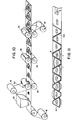
- Fig. 9 depicts a production process for the coffee-filter pouch according to Fig. 1.
- Two webs 18, 19 are unwound from supply reels 20, 21 and move upwards over two first heatsealing cylinders 22 and through the cylinder gap formed thereby.
- the first heatsealing cylinders 22 form the heatsealing seams for the bottom edge 6 and the two lateral (side) edges 4, 5.
- the metered quantity of coffee powder 9 is added through a filling funnel 23 to the cylinder gap. Addition of the coffee powder 9 is coupled with respect to time with the angle of rotation of the heatsealing cylinders 22 so that the coffee powder 9 is added at a point in time immediately subsequently to production of the heatsealing seam of the bottom edge 6.
- cut-outs 50 in the filter material web which serve to form the grip lips 8a.
- the controls of the various heatsealing cylinders and of the cutting or die-cutting cylinders takes place in a manner such that the cut-outs 50 come to lie at the upper end of the tabs 8, so that the tab 8 of the other filter material web 19, which does not contain any such cut-outs, is a little longer and in that way forms the grip lip 8a.
- Fig. 10 The process shown diagramatically in Fig. 10 is similar to that of Fig. 9, but the various pairs of cylinders are not positioned vertically above one another but, rather, are positioned in a horizontal plane.
- the bottom web 18 is supplied horizontally, and the already metered portions (servings) of coffee powder are applied thereto before the upper web is supplied from the top into the cylinder gap of the first heatsealing cylinders 22.
- the heatsealing regions 28 of the heatsealing cylinders are arranged in a manner such that the heatsealing seams point with the bottom edge 6 in the direction of conveyance of the webs 18, 19.
- Fig. 11 shows a top view (bird's eye view) onto a material-saving arrangement of the heatsealing seams on the webs 18, 19.
- the lateral edges 4, 5 of successive coffee-filter pouches are in that respect contacting one another, and the bottom edges 6 point alternatingly to the one and to the other side.
- the portions of the web beneath the lateral edges 4, 5 are then cut out through conical cutting jaws 33 which are likewise movable transversely to the web 30. Subsequently thereto, the metered quantity of the coffee powder 9 is filled in through a filling chute 34, whose outflow opening is located between the two upper edges of web 30. Further heatsealing jaw 35 then join the two upper edges of web 30 to produce the heatsealing seam along the upper edge 7 of the filter pouch, and finally the portions of the web 30 projecting beyond the grip tabs 8 are severed through further cutting jaws 36.
- the individual coffee-filter pouches 1 then drop onto a chute 26 and are optionally packaged individually or in groups.
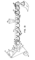
- FIG. 13 schematically shows the course of a process for producing a coffee-filter pouch 1 according to Fig. 2 with the insert 10.
- a single web 40 moves from a supply reel through between a pair of cutting cylinders 41, with rhombic cut-outs 42 being produced along the center line of the web, the significance of which results from the further course of the process.
- a wedge-shaped folding means 43 serves to then fold the web 40 in W-configuration, and said web then moves through supply cylinders 44.
- the sealing seam along the upper edge 7 and of the lateral edges 4, 5, which largely follow it, of the filter pouch are produced through a first pair of laterally movable sealing jaws 45.
- the filter pouch is positioned upside down in that connection, i.e., the upper edge 7 is disposed at the bottom end of the folded web 40.
- the distance (d) of the tips pointing toward one another of two successive rhombic cutouts 42 correspond to the width of the insert 10 along line 11 in Fig. 2.
- the rhombic cut-outs 42 serve to make sure that the inserts 10 are heatsealed only along the inner regions 14 of Fig. 2 to the layers 2, 3, while the layers 2 and 3 are heatsealed together along the outer regions 15.
- the portions of the folded web 40 which project beyond the upper edge 7 are cut out through first cutting jaws 46.
- the semi-finished filter pouches are filled from their botton side through a filling chute 47, whose outflow opening dips in between the upper edges of the folded web 40. After that has been done, the bottom side is closed through production of the heatsealing seam forming the bottom edge 6. This takes place by means of second sealing jaws 48. Through second cutting jaws 49 the portions of the folded web 40 which are left between the lateral edges 4 and 5 of two successive filter pouches are then cut out. The finished filter pouch then is stacked, further packaged or the like.
- Water-permeable filter paper capable of being heat sealed and fed in roller form as continuous web material serves as the filter material 2, 3.
- Said filter paper consists on the outer side of about 15-25 grams per square meter of purest cellulose-/ Manila fibers as nonwoven fiber batt, said fibers being neutral in taste, which are lined on the inner side with about 3-6 grams per square meter of thermoplastic polyolefin fibers stable over against boiling water so as to attain heatsealability.
- Other materials such as pure synthetic fiber batts or needle-perforated synthetic material films optionally coated to render them heatsealable may also be used.
- the sealing temperatures amount to about 120-190°C.
- the filter pouches can be produced at performances of, typically, 30-90 pouches per minute in intermittent mode of operation according to Fig. 12 and 13, or in rotating mode of operation according to Fig. 9-11.
- the rotating processes according to Fig. 9-11 may also be made to involve a plurality of webs, with the performance thus being multiplied accordingly.
- processes according to Fig. 12 and 13 in rotating mode of procedure also allow for a production rate increased by several times.
- the processes according to Fig. 9-11 finally, can also be laid out to run off intermittently, in which regard it is worked, in lieu of with sealing cylinders, with sealing jaws similarly to Fig.
- a typical filter pouch size according to Fig. 2 for a 4-cup serving contains about 25 grams of coffee powder 9.
- the height dimensions are about 130 millimeters at an angle of closing of about 77°, and at a lower sealing edge length of 6 of about 50 millimeters there results an upper width of about 200 millimeters as length of section.
- the radius of the closing, upper circular arc 7 is about 160 millimeters
- the edges 4, 5 have a length of about 120 millimeters.
- the sealing edges are 3-8 millimeters wide, with greater sealing edge widths being employed in particular in the region of welding of the insert 10 to the edges 4, 5 in the region 14, 15.
- the minimum depth of the insert 10 is 67 millimeters, but it preferably has a depth of 75-95 millimeters so as to create a sufficiently large space for pouring in the water, which suffices for manual preparation rate of about 60 pouches per minute according to the process of Fig. 13, the sealing temperatures amount to about 160°C.
- the sealing temperatures in the cylinder pair 22 are about 170°C, and in the cylinder pair 24 they are about 150°C.
- the respective sealing pressures are to be adjusted empirically, as they customarily cannot be continually measured and re-adjusted without special effort on such production machines.
Landscapes
- Engineering & Computer Science (AREA)
- Mechanical Engineering (AREA)
- Packages (AREA)
- Apparatus For Making Beverages (AREA)
- Filtering Materials (AREA)
Abstract
Description
- The invention relates to a conical coffee or tea filter pouch to produce filtered coffee or, resp., tea by means of brewing coffee powder or, resp. tea leaves with boiling water. The filter pouch has two layers of a water-permeable filter material, which are joined at the edges to form a package receiving the coffee powder or, resp., the tea leaves. The circular-segment-configured shape of the filter pouch makes it particularly suited for insertion into the commercially customary conical filter holding cones on coffee machines or coffee pots. Furthermore, it is suited in particular for producing amounts of coffee for several cups. The invention relates, furthermore, to a process for producing the coffee-filter pouch in a continuous production operation.
- Coffee-filtering pouches of two layers of paper or other water-permeable filter material are known from the DE-Al-22 18 081 and 27 38 969. The layers are joined at their edges through mechanical pressure, through adhesive bonding or through welding. The other edges are folded. The coffee pouch according to DE-A1 27 38 969 is used similarly as a tea bag to produce individual portions of coffee and is, for that purpose, hung into the cup. A drawback that is involved here is that the water that is poured on cools rapidly in the cup and in that way not all of the aromatic substances are extracted from the coffee powder, so that this type of production of individual portions of coffee is not satisfactory from the standpoint of taste, and the cups are half empty after the filter pouch is removed, as the coffee powder absorbs a large quantity of water. The coffee-filter pouches according to DE-A1 22 18 081 are: similar to filter bags; used to produce filter coffee; they are, however, difficult to produce, as they are made of internested bags. Though said printed publication also describes a process of producing the filter pouch from an endless paper tube, said filter pouch then has, however, a rectangular shape that is unsuited for insertion into the commercial conical filter holding cones of coffee machines and coffee pots. Moreover, there results a separation of the swelling chamber and non-uniform accumulation of the coffee powder, with a substantial part of the water poured on, thus flowing through the filter without adequately penetrating through the coffee powder.
- A coffee-filter pouch is known from US-A-3,971,305, which consists of a truncated-cone-shaped filter bag, in which the coffee powder is enclosed. This filter bag is secured in a truncated-cone-shaped holder consisting of rigid material for placement onto a cup. The production of that type of filtering bags is such as to involve extraordinary effort and is in no proportion to the price of the coffee powder if an amount of coffee is to be prepared from one or a few cups.
- The invention is based on the object to provide a coffee-filter pouch, which makes it possible to produce a good-tasting filter coffee or tea beverage for a plurality of cups, and the production costs of which are low, and to provide as well a corresponding process.
- Said object is accomplished in that the filter material is heat-sealable only on one side, and in that the sealing seams to extend at least over the lateral edges of the filter pouch.
- It is made possible in that way to produce the filter pouch by a continuous process, i.e., to shape it, seal it, fill it, and close and die-cut it. Hence, a process, in which all heat-sealing seams and die-cuttings can be produced in a single or in two integrated steps, but in a single pass (operating cycle). In the process according to the invention, for example two webs are in that connection brought together in a gap of a pair of heatsealing cylinders, a metered volume of coffee powder is simultaneously added in the roller gap, and the thus formed filter pouch is then cut or die-cut out of the webs. One of the difficulties encountered in the production of filled filter pouches is that the layers of the filter material no longer come lie, on account for the filling, flat one on the other but, rather, are more or less arched. Disturbing folds can form when that kind of webs is heatsealed. According to the invention, therefore, a part of the sealing seams is produced already before, or at the latest during, the addition of the coffee powder. It is for that same reason and for utmost reliability that a part of the die-cuttings also is produced prior to addition of the coffee powder, so that it is ensured that the finished filter pouch has uniformly wide sealing edges.
- While pouches for foods and other articles of use customarily have only heatsealing seams that are horizontal and vertical, at right angles to one another, form- and contour-sealing may take place in the process according to the invention. It is made possible in that way that the filter pouch of the invention has heatsealing seams, which do not extend at right angles to one another, in which way, for example, the conical shape of the filter pouch is attained. Another peculiar aspect of the process of the invention resides in that the individual heatsealing seams are formed in one operating step. In particular, the production of the upper heatsealing seam is to take place separately in order to make the upper edge of the filter pouch capable of being pulled open, which requires lower temperatures and lower pressures during heatsealing.
- To enable the filter pouch to be used in the same way as a conventional coffee filter, with the difference being that the coffee powder is already pre-packaged in the filter pouch, the filter pouch is preferably designed such that the two layers of the filter paper can be separated along the upper edge, i.e., the filter pouch can be opened at that location. To that end, the heatsealing seam is designed weaker along the upper edge, so that, though it is tight and secure enough to prevent coffee powder from flowing out, it nevertheless remains capable of being pulled or torn open. There furthermore is expediently provided along the upper edge a projecting grip tab which facilitates pulling or tearing the filter pouch open. Another possibility is to join the two layers of the filter material along the upper edge not to one another, but rather to a folded gusset (insert) of the filter material, which, starting from the uppper edge, also joins a portion of the lateral edges to the two layers of the filter material. In that connection, the two layers may along this upper part of the lateral edges be heatsealed only with the gusset. The gusset preferably is designed to be a little more narrow than the two layers of filter material, so that the two layers are heatsealed along this upper part of the lateral edges with one another as well as also with the gusset. The two layers are heatsealed together along the outer region of the lateral edges, while they are heatsealed on the following, inner region of the lateral edges not with one another but, rather, with the outwardly facing areas of the gusset. The heatsealing seam in this region may additionally, however, be designed to be somewhat wider. When the filter pouch is folded open, the gusset then spans the upper opening of the filter pouch, so that even in the event of maladroit manipulation there does not exist any danger that coffee powder drops out of the filter pouch. Preferably the insert should have sufficient depth that it is spanned in a plane low enough to leave sufficient room for holding all the water (required for several cups) poured in at once, as is commonly done when preparing coffee in the traditional way.
- That type of coffee-filtering pouches is preferably produced in a manner such that a single filter material web is longitudinally folded in W-shaped manner through wedge-shaped forming members and then the sealing seams are produced in a manner such that the filter pouch points upwards with the bottom edge. In that regard, at first the sealing seams along the downwardly pointing upper edge and the portion of the lateral edges which follows are produced. There then is inserted through the bottom of the latter filter pouch a predetermined amount of the coffee powder, and subsequently thereto the bottom edge and the remaining portion of the lateral edges that follows are heatsealed. The filter pouch then is ready and may be cut or die-cut out of the web.
- Even though the filter material may be heatsealed only on one side, it is possible to heatseal together all four layers in the botton region of the W-shaped fold, with the two inner layers then constituting the insert. To that end, rhombic cut-outs are provided along the center line of the filter material web, the one diagonal of which cut-outs coincides with the center line of the web. The spacing between the tips of the rhombic cut-outs corresponds to the bottom width of the insert.
- To enable the filter pouch to be positioned within conventional truncated-cone-shaped coffee filter holders, the lateral edges enclose an angle of between 60° and 90°, and the filter pouch on the whole has the configuration of about a circular sector with the tip cut off. Other pouch configurations which likewise are in accordance with the invention are depicted in Figures 5-8.
- Exemplary embodiments of the invention will be explained below with the aid of the drawing, which shows in:
- Fig. 1: a coffee-filter pouch with a heatsealing seam adapted to be pulled open along the upper edge;
- Fig. 2: a coffee-filter pouch with gusset (insert);
- Fig. 3: the coffee-filter pouch of Fig. 2 in a section taken along lines 3-3 in closed condition;
- Fig. 4: the coffee-filter pouch according to Fig. 2 in a section along 3-3 in opened condition;
- Fig. 5 to 8: further geometric shapes of the coffee-filter pouch;
- Fig. 9 to 12: simplified, schematic representations of the conduction of the process of producing a coffee-filter pouch as according to Fig. 1 and
- Fig. 13: a simplified, schematic representation of the conduction of the process for producing a coffee-filter pouch as according to Fig. 2.
- Fig. 1 shows a front view of a coffee-filter pouch 1, which includes two
layers 2, 3 of filter material, which are joined together along thelateral edges bottom edge 6 and thetop edge 7 through heatsealing seams. The heatsealing seams are depicted in hatched lines in the drawing. The heatsealing seam along theupper edge 7 is produced under lower temperature and/or lower pressure, so that it is adapted to be pulled open or torn open. To facilitate pulling or tearing open,tabs 8 of eachlayer 2, 3 project beyond theupper edge 7. Thelayers 2, 3 may be grasped by said tabs and be pulled apart. Preferably these tabs may also project to different height with, for example, a 2-3 millimeter distance, thus forming agrip lip 8a, which still further facilitates opening. The coffee-filter pouch 1 then in function corresponds to a conventional filter bag provided with coffee powder and is manipulated in the same way, i.e., is inserted into a truncated-cone-shaped filter bag holder, into which boiling water is poured for brewing the coffee. This is done either by hand, when the holder is placed onto coffee pots, or automatically in all types of embodiment of commercial filter-coffee machines. - The coffee-filter pouch serves as an envelopment for a precisely measured, unchanging quantity of
coffee powder 9 or tea leaves, so that a beverage of uniform quality can be prepared. In that regard, coffee or tea powder quantities and filter pouch sizes for 2, 4 and 6 to 10 cup portions are being preferably produced. - Fig. 2 to 4 show a coffee-filter pouch 1 with an
insert 10. The twolayers 2, 3 of the filter paper are connected together through a heatsealing seam along thelateral edges bottom edge 6. - The
insert 10, which consists of filter material permeable to boiling water and folded along line 11, is located in the upper region of the coffee-filter pouch 1. Theinsert 10 is positioned in the manner of a gusset (gore) in the upper region of the coffee-filter pouch 1 and is to make it possible to fold open the coffee-filter pouch 1, without there being any need for pulling open a heatsealing seam. - The folded
insert 10 consists of twosheets sheets upper edge 7 with one of thelayers 2, 3 through a heatsealing seam. It is also connected with said layer 2 or, resp., 3 through a heatsealing seam until down to line 11 along thelateral edges insert 10 is a few millimeters more narrow in transverse direction than saidlayers 2, 3, so that said heatsealing seam extends between saidsheets layers 2, 3 only over about half the width of said heatsealing seam, i.e., theinner region 14. Thelayers 2, 3 are connected together longitudinally of the outer region 15. Therefore, there exists along the upper part of thelateral edges 4, 5 a connection of the twosheets layers 2, 3 of said filter material. The insert is either produced of the same filter material aslayers 2, 3 from a single web of material - with its water-permeability optionally still enhanced through additional minutest needle perforation - , or it is formed of a second web of material of the same or of different filtering material. - In use, the coffee-filter pouch 1 according to Figures 2 to 4 is placed into a conventional filter bag holder, with the two
layers 2, 3 generally separating of their own along theupper edges 7, or else they are pushed apart by hand. Thecoffee powder 9 enclosed within the coffee-filter pouch is then in customary manner brewed with boiling water, with the water that is poured-on penetrating at first through the filter material of the insert before wetting and extracting the coffee powder. - The Figures 5 to 8 show further forms of the coffee-filter pouch. In the embodiment according to Figure 5, the
upper edge 7 is not designed to have the shape of a circular line but, rather, to be straight with end regions extending at right angles thereto which merge into thelateral edges upper edge 7 may be of like strength as the remaining sealing seams, and in use the coffee-filter pouch is cut open at theedge 7. In coffee machines having a filter-cover to retain aroma, cutting open occurs according to the sector line shown by a dash-and-dot line and connecting the two upper ends of thelateral edges - In the embodiment as according to Figures 6 and 7, the projecting
regions 16 have been left to stand. Production of the coffee-filter pouch is simplified in that way. On insertion of the coffee-filter pouch according to Fig. 6 and 7 into a filter bag holder, the projectingregions 16 are folded over thelateral edges layers 2, 3. The flow resistance on passage of the brewing water through the filter material then is increased in these portions, so that premature passage of the brewing water through the upper regions oflayers 2, 3 is somewhat hindered, and the water for brewing is passed through the full layer thickness of thecoffee powder 9. In the embodiments of Figures 6 and 7, theinsert 10 is present. The projectingregions 16 may, however, be left to stand also in the case of the embodiment according to Fig. 1, in which the heatsealing seam is adapted to be torn open or pulled open along theupper edge 7. - Fig. 8 shows a modification of the embodiment according to Fig. 2, with the heatsealing seam on the
lateral edges edge 7 may be omitted on account of the insert being folded. For brewing coffee by hand or in coffee machines without filter-cover, this embodiment can be utilized as in the case of the filter pouch as according to Fig. 2. - Fig. 9 depicts a production process for the coffee-filter pouch according to Fig. 1. Two
webs supply reels first heatsealing cylinders 22 and through the cylinder gap formed thereby. Thefirst heatsealing cylinders 22 form the heatsealing seams for thebottom edge 6 and the two lateral (side) edges 4, 5. At the same time, the metered quantity ofcoffee powder 9 is added through a fillingfunnel 23 to the cylinder gap. Addition of thecoffee powder 9 is coupled with respect to time with the angle of rotation of theheatsealing cylinders 22 so that thecoffee powder 9 is added at a point in time immediately subsequently to production of the heatsealing seam of thebottom edge 6. - There are contained small rectangular cut-
outs 50 in the filter material web which serve to form thegrip lips 8a. The controls of the various heatsealing cylinders and of the cutting or die-cutting cylinders takes place in a manner such that the cut-outs 50 come to lie at the upper end of thetabs 8, so that thetab 8 of the otherfilter material web 19, which does not contain any such cut-outs, is a little longer and in that way forms thegrip lip 8a. - The
filter material webs second heatsealing cylinders 24, which produce the heatsealing seam, which is adapted to be torn or pulled open, along theupper edge 7. - It is advisable to separate the heatsealing pairs in 22 and 24 so as to form the upper edge such as to be capable of being readily pulled open through sealing conditions different from
edges heatsealing cylinders 22, with thecylinder pair 24 thus being omitted. The coffee-filter pouch is then finish- sealed and only still needs to be cut out from thewebs cylinders 25. After passage through the two cutting or die-cuttingcylinders 25, the coffee-filter pouch 1 drops onto a chute or aconveyor belt 26, which conducts it to possible further packaging stations. The remainder ofwebs waste material cylinder 27. - The process shown diagramatically in Fig. 10 is similar to that of Fig. 9, but the various pairs of cylinders are not positioned vertically above one another but, rather, are positioned in a horizontal plane. The
bottom web 18 is supplied horizontally, and the already metered portions (servings) of coffee powder are applied thereto before the upper web is supplied from the top into the cylinder gap of thefirst heatsealing cylinders 22. - In the process according to Figures 9 and 10, the
heatsealing regions 28 of the heatsealing cylinders are arranged in a manner such that the heatsealing seams point with thebottom edge 6 in the direction of conveyance of thewebs webs bottom edges 6 point alternatingly to the one and to the other side. - While two
material webs single web 30 is being supplied in the schematic diagram of the process shown in Fig. 12, which web is being folded along the center line by means of a fold-formingwedge 29. The foldedweb 30 then extends through between twoguide cylinders 31, with the fold being located at the bottom and the two web edges at the top. The heatsealing seams at thebottom edge 6 and at thelateral edges heatsealing jaws 32 movable transversely in relation to the web. Due to the fold-formation, heatsealing of thebottom edge 6 may also be omitted in the case of this production process. The portions of the web beneath thelateral edges jaws 33 which are likewise movable transversely to theweb 30. Subsequently thereto, the metered quantity of thecoffee powder 9 is filled in through a fillingchute 34, whose outflow opening is located between the two upper edges ofweb 30.Further heatsealing jaw 35 then join the two upper edges ofweb 30 to produce the heatsealing seam along theupper edge 7 of the filter pouch, and finally the portions of theweb 30 projecting beyond thegrip tabs 8 are severed through further cuttingjaws 36. The individual coffee-filter pouches 1 then drop onto achute 26 and are optionally packaged individually or in groups. - Fig. 13 schematically shows the course of a process for producing a coffee-filter pouch 1 according to Fig. 2 with the
insert 10. Asingle web 40 moves from a supply reel through between a pair of cuttingcylinders 41, with rhombic cut-outs 42 being produced along the center line of the web, the significance of which results from the further course of the process. A wedge-shaped folding means 43 serves to then fold theweb 40 in W-configuration, and said web then moves throughsupply cylinders 44. The sealing seam along theupper edge 7 and of thelateral edges jaws 45. In the course of production, the filter pouch is positioned upside down in that connection, i.e., theupper edge 7 is disposed at the bottom end of the foldedweb 40. The distance (d) of the tips pointing toward one another of two successiverhombic cutouts 42 correspond to the width of theinsert 10 along line 11 in Fig. 2. The rhombic cut-outs 42 serve to make sure that theinserts 10 are heatsealed only along theinner regions 14 of Fig. 2 to thelayers 2, 3, while thelayers 2 and 3 are heatsealed together along the outer regions 15. The portions of the foldedweb 40 which project beyond theupper edge 7 are cut out through first cuttingjaws 46. The semi-finished filter pouches are filled from their botton side through a fillingchute 47, whose outflow opening dips in between the upper edges of the foldedweb 40. After that has been done, the bottom side is closed through production of the heatsealing seam forming thebottom edge 6. This takes place by means of second sealingjaws 48. Throughsecond cutting jaws 49 the portions of the foldedweb 40 which are left between thelateral edges - The sequence of some of the process steps shown in Figures 12 and 13 may optionally be changed. For example, the filling
chute 34 or, resp., 47 may be located in front of thefirst cutting jaws 33 or, resp. 46. Cutting out of the filter pouch may also take place in a single process step through a single pair of cutting jaws if sufficiently wide and secure sealing edges on the finished filter pouch can be ensured thereby. - Water-permeable filter paper capable of being heat sealed and fed in roller form as continuous web material serves as the
filter material 2, 3. Said filter paper consists on the outer side of about 15-25 grams per square meter of purest cellulose-/ Manila fibers as nonwoven fiber batt, said fibers being neutral in taste, which are lined on the inner side with about 3-6 grams per square meter of thermoplastic polyolefin fibers stable over against boiling water so as to attain heatsealability. Other materials, such as pure synthetic fiber batts or needle-perforated synthetic material films optionally coated to render them heatsealable may also be used. Depending upon material thickness, type of material and production speed, etc., the sealing temperatures amount to about 120-190°C. Dependent upon the required production performance and conditioned by which of the described production processes (Fig. 9-13) is employed, the filter pouches can be produced at performances of, typically, 30-90 pouches per minute in intermittent mode of operation according to Fig. 12 and 13, or in rotating mode of operation according to Fig. 9-11. For higher performances the rotating processes according to Fig. 9-11 may also be made to involve a plurality of webs, with the performance thus being multiplied accordingly. Depending upon type of design, processes according to Fig. 12 and 13 in rotating mode of procedure also allow for a production rate increased by several times. The processes according to Fig. 9-11, finally, can also be laid out to run off intermittently, in which regard it is worked, in lieu of with sealing cylinders, with sealing jaws similarly to Fig. 12 and 13. A typical filter pouch size according to Fig. 2 for a 4-cup serving contains about 25 grams ofcoffee powder 9. The height dimensions are about 130 millimeters at an angle of closing of about 77°, and at a lower sealing edge length of 6 of about 50 millimeters there results an upper width of about 200 millimeters as length of section. In that respect the radius of the closing, uppercircular arc 7 is about 160 millimeters, theedges insert 10 to theedges region 14, 15. The minimum depth of theinsert 10 is 67 millimeters, but it preferably has a depth of 75-95 millimeters so as to create a sufficiently large space for pouring in the water, which suffices for manual preparation rate of about 60 pouches per minute according to the process of Fig. 13, the sealing temperatures amount to about 160°C. In the production of the pull-open-type filter pouches according to Fig. 1 by the processes of Fig. 9-11 and at a production rate of about 40-50 pouches per minutes, the sealing temperatures in thecylinder pair 22 are about 170°C, and in thecylinder pair 24 they are about 150°C. The respective sealing pressures are to be adjusted empirically, as they customarily cannot be continually measured and re-adjusted without special effort on such production machines. - All of the measurements mentioned in the Example for other filter pouch sizes, e.g. for 2, 6, 8 and 10 cups, are completely different, except for the closing angle and the
edge length 6. The closing angle andedge length 6 may also vary, depending upon the conicalness (taper) of the filter holding system. Though the description of the Figures only relates to coffee-filter pouches, it in the same way also applies, however, for tea-filter pouches.
Claims (7)
Applications Claiming Priority (2)
| Application Number | Priority Date | Filing Date | Title |
|---|---|---|---|
| DE3446403 | 1984-12-19 | ||
| DE19843446403 DE3446403A1 (en) | 1984-12-19 | 1984-12-19 | COFFEE OR TEA FILTER BAGS AND METHOD FOR THE PRODUCTION THEREOF |
Publications (2)
| Publication Number | Publication Date |
|---|---|
| EP0186867A2 true EP0186867A2 (en) | 1986-07-09 |
| EP0186867A3 EP0186867A3 (en) | 1988-03-23 |
Family
ID=6253246
Family Applications (1)
| Application Number | Title | Priority Date | Filing Date |
|---|---|---|---|
| EP85116268A Withdrawn EP0186867A3 (en) | 1984-12-19 | 1985-12-19 | Coffee or tea filter pouch and process of producing it |
Country Status (5)
| Country | Link |
|---|---|
| EP (1) | EP0186867A3 (en) |
| JP (1) | JPS61178864A (en) |
| DE (1) | DE3446403A1 (en) |
| DK (1) | DK589685A (en) |
| ES (2) | ES8704838A1 (en) |
Cited By (13)
| Publication number | Priority date | Publication date | Assignee | Title |
|---|---|---|---|---|
| GB2214481A (en) * | 1988-01-20 | 1989-09-06 | Gerald Lightfoot | Package, method of packaging and packaging apparatus |
| GB2218685A (en) * | 1988-05-20 | 1989-11-22 | William Grant Carney | Teabag |
| US5132124A (en) * | 1990-05-18 | 1992-07-21 | Pokka Corporation | Powdered drink brewing bag |
| FR2686495A1 (en) * | 1992-01-24 | 1993-07-30 | Cafes Cie Mediterraneenne | Package for ground coffee for coffee machine acting as a filter |
| WO1995019301A1 (en) * | 1994-01-17 | 1995-07-20 | M.T.R. S.R.L. | Disposable filter for preparation of hot brewed beverages |
| GB2337738A (en) * | 1998-05-30 | 1999-12-01 | George Payne & Co Ltd | Producing gusseted infusion packages |
| EP1164080A1 (en) * | 2000-05-11 | 2001-12-19 | Teepack Spezialmaschinen Gmbh & Co. Kg | Method and apparatus for continuously manufacturing infusion bags as well as the infusion bag itself |
| US6505731B2 (en) | 2001-02-09 | 2003-01-14 | Teepack Spezialmaschinen Gmbh & Co. Kg | Transport device for strand materials in continuous production of infusion bags for making tea |
| US6725628B2 (en) | 2000-05-11 | 2004-04-27 | Teepack Spezialmaschinen Gmbh & Co. Kg | Process for the continuous production of beverage filter bags |
| FR2871144A1 (en) * | 2004-06-08 | 2005-12-09 | Segafredo Zanetti France Sa | Filter bag for e.g. electric coffee maker, has walls joined in edges to peripherally close bag while defining volume to enclose product, where closing is reversible to define opening zone in which walls are separated manually |
| NL2002803C2 (en) * | 2009-04-24 | 2010-10-26 | Sara Lee De Nv | FILTER AND METHOD FOR MANUFACTURING A FILTER. |
| WO2021122683A1 (en) * | 2019-12-18 | 2021-06-24 | Société des Produits Nestlé S.A. | Container with tab |
| RU2765509C1 (en) * | 2018-01-22 | 2022-01-31 | МЕЛИТТА СИНГЛ ПОРШНС ГМБХ унд КО. КГ | Method for preparing beverage using portioned packaging and portioned packaging |
Citations (4)
| Publication number | Priority date | Publication date | Assignee | Title |
|---|---|---|---|---|
| DE2515946A1 (en) * | 1975-04-11 | 1976-10-21 | Bentz & Sohn Melitta | Coffee filter bag for small quantities - tapered closed end with suspension means at opposite open end |
| FR2380057A1 (en) * | 1977-02-14 | 1978-09-08 | Wagner Marc | Rolls of cone-shaped filter papers prodn. - using rollers to emboss shapes and perforate two superimposed strips of filter paper |
| DE3005793A1 (en) * | 1980-02-15 | 1981-08-20 | Schoeller & Hoesch KG, 7562 Gernsbach | Porous filter paper with synthetic material dots - in grid pattern, for cigarette filter tips or tea bags |
| EP0095542A1 (en) * | 1982-05-28 | 1983-12-07 | Nicolas Goedert | Method and apparatus for manufacture of filter bag for infusion products |
Family Cites Families (7)
| Publication number | Priority date | Publication date | Assignee | Title |
|---|---|---|---|---|
| DE832874C (en) * | 1950-09-07 | 1952-02-28 | Ind Werke Karlsruhe A G | Device for packing powdery, grainy, small pieces and pasty goods |
| DE1849793U (en) * | 1960-10-10 | 1962-04-12 | Hesser Ag Maschf | Infusion bags. |
| DE1138678B (en) * | 1960-11-10 | 1962-10-25 | Hesser Ag Maschf | Process for the continuous production of filled multi-chamber bags |
| DE2218081A1 (en) * | 1972-04-14 | 1973-10-31 | Guenter Busch | FILTER INSERT FOR FILTER ATTACHMENTS ON BREWING OR FOOD DEVICES FOR COFFEE, TEA OR. DGL |
| DE2738969A1 (en) * | 1977-08-30 | 1979-03-15 | Martin Ruediger | Coffee bag for infusion in cup - has powder or granules stored in filter paper funnel which is sealed in airtight bag |
| IT1133279B (en) * | 1980-04-17 | 1986-07-09 | Ima Spa | VOLUMETRIC DOSER FOR INCONERENT PRODUCTS, PARTICULARLY SUITABLE FOR FAST PACKAGING MACHINES-FILTER BAGS FOR INFUSION PRODUCTS SUCH AS YOU, CHAMOMILE AND SIMILAR |
| BE884111A (en) * | 1980-07-01 | 1980-11-03 | Moortgat Maria G | PRE-FILLED FILTER BAG FOR COFFEE MACHINE |
-
1984
- 1984-12-19 DE DE19843446403 patent/DE3446403A1/en not_active Withdrawn
-
1985
- 1985-12-18 ES ES550102A patent/ES8704838A1/en not_active Expired
- 1985-12-18 DK DK589685A patent/DK589685A/en not_active Application Discontinuation
- 1985-12-19 JP JP60286842A patent/JPS61178864A/en active Pending
- 1985-12-19 EP EP85116268A patent/EP0186867A3/en not_active Withdrawn
-
1987
- 1987-02-16 ES ES1987296178U patent/ES296178Y/en not_active Expired
Patent Citations (4)
| Publication number | Priority date | Publication date | Assignee | Title |
|---|---|---|---|---|
| DE2515946A1 (en) * | 1975-04-11 | 1976-10-21 | Bentz & Sohn Melitta | Coffee filter bag for small quantities - tapered closed end with suspension means at opposite open end |
| FR2380057A1 (en) * | 1977-02-14 | 1978-09-08 | Wagner Marc | Rolls of cone-shaped filter papers prodn. - using rollers to emboss shapes and perforate two superimposed strips of filter paper |
| DE3005793A1 (en) * | 1980-02-15 | 1981-08-20 | Schoeller & Hoesch KG, 7562 Gernsbach | Porous filter paper with synthetic material dots - in grid pattern, for cigarette filter tips or tea bags |
| EP0095542A1 (en) * | 1982-05-28 | 1983-12-07 | Nicolas Goedert | Method and apparatus for manufacture of filter bag for infusion products |
Cited By (16)
| Publication number | Priority date | Publication date | Assignee | Title |
|---|---|---|---|---|
| GB2214481A (en) * | 1988-01-20 | 1989-09-06 | Gerald Lightfoot | Package, method of packaging and packaging apparatus |
| GB2218685A (en) * | 1988-05-20 | 1989-11-22 | William Grant Carney | Teabag |
| US5132124A (en) * | 1990-05-18 | 1992-07-21 | Pokka Corporation | Powdered drink brewing bag |
| FR2686495A1 (en) * | 1992-01-24 | 1993-07-30 | Cafes Cie Mediterraneenne | Package for ground coffee for coffee machine acting as a filter |
| WO1995019301A1 (en) * | 1994-01-17 | 1995-07-20 | M.T.R. S.R.L. | Disposable filter for preparation of hot brewed beverages |
| US5582731A (en) * | 1994-01-17 | 1996-12-10 | M.T.R. S.R.L. | Disposable filter for preparation of hot brewed beverage |
| GB2337738B (en) * | 1998-05-30 | 2002-07-17 | Payne Co Ltd George | Infusion packages |
| GB2337738A (en) * | 1998-05-30 | 1999-12-01 | George Payne & Co Ltd | Producing gusseted infusion packages |
| EP1164080A1 (en) * | 2000-05-11 | 2001-12-19 | Teepack Spezialmaschinen Gmbh & Co. Kg | Method and apparatus for continuously manufacturing infusion bags as well as the infusion bag itself |
| US6725628B2 (en) | 2000-05-11 | 2004-04-27 | Teepack Spezialmaschinen Gmbh & Co. Kg | Process for the continuous production of beverage filter bags |
| US6505731B2 (en) | 2001-02-09 | 2003-01-14 | Teepack Spezialmaschinen Gmbh & Co. Kg | Transport device for strand materials in continuous production of infusion bags for making tea |
| FR2871144A1 (en) * | 2004-06-08 | 2005-12-09 | Segafredo Zanetti France Sa | Filter bag for e.g. electric coffee maker, has walls joined in edges to peripherally close bag while defining volume to enclose product, where closing is reversible to define opening zone in which walls are separated manually |
| NL2002803C2 (en) * | 2009-04-24 | 2010-10-26 | Sara Lee De Nv | FILTER AND METHOD FOR MANUFACTURING A FILTER. |
| WO2010123368A1 (en) * | 2009-04-24 | 2010-10-28 | Sara Lee/De N.V. | Filter and method for manufacturing a filter |
| RU2765509C1 (en) * | 2018-01-22 | 2022-01-31 | МЕЛИТТА СИНГЛ ПОРШНС ГМБХ унд КО. КГ | Method for preparing beverage using portioned packaging and portioned packaging |
| WO2021122683A1 (en) * | 2019-12-18 | 2021-06-24 | Société des Produits Nestlé S.A. | Container with tab |
Also Published As
| Publication number | Publication date |
|---|---|
| DK589685D0 (en) | 1985-12-18 |
| ES550102A0 (en) | 1987-04-16 |
| EP0186867A3 (en) | 1988-03-23 |
| DK589685A (en) | 1986-06-20 |
| JPS61178864A (en) | 1986-08-11 |
| DE3446403A1 (en) | 1986-07-17 |
| ES296178U (en) | 1987-08-01 |
| ES296178Y (en) | 1988-02-16 |
| ES8704838A1 (en) | 1987-04-16 |
Similar Documents
| Publication | Publication Date | Title |
|---|---|---|
| EP0186867A2 (en) | Coffee or tea filter pouch and process of producing it | |
| US4853234A (en) | Beverage packages | |
| US2362459A (en) | Infusion package and the manufacture thereof | |
| EP1966060B1 (en) | Beverage preparation capsules | |
| EP0615921A1 (en) | Rigid cartridge for coffee or the like | |
| US3337117A (en) | Beverage package | |
| US4055668A (en) | Infusion package | |
| NO831645L (en) | PROCEDURE AND DRINK PREPARATION DEVICE | |
| CA2039256A1 (en) | Beverage packages | |
| EP0389141B1 (en) | Beverage packages | |
| EP0918706B1 (en) | Drink-extracting bag equipped with holding element | |
| US4417433A (en) | Method of making infusion package | |
| US2571138A (en) | Infusion package with expandible bottom and method of manufacture thereof | |
| EP1016599B1 (en) | Two-lobed filter bag for products for infusion and method for making the same | |
| EP1327589B1 (en) | Infusion bag with thread and tag and its method of manufacture | |
| JP2540379B2 (en) | Filter for ingredient-eluting preference foods-Method for manufacturing bag-filled products | |
| EP1375384A2 (en) | A drip bag | |
| IE48873B1 (en) | Disposable filter bag and a method of making extraction beverages | |
| JPH10165309A (en) | Filtering device for coffee, tea, etc. | |
| JP3595050B2 (en) | Preference beverage bag with support | |
| JP7129081B2 (en) | drip bag | |
| JP2949160B2 (en) | Drinking material filling pack, drinking material filling pack manufacturing apparatus, and drinking material filling pack manufacturing method | |
| JP4043908B2 (en) | Drip bag | |
| JP2000313411A (en) | Leaching package, and method and device for making the same | |
| GB2224264A (en) | Infusion or cooking bag |
Legal Events
| Date | Code | Title | Description |
|---|---|---|---|
| PUAI | Public reference made under article 153(3) epc to a published international application that has entered the european phase |
Free format text: ORIGINAL CODE: 0009012 |
|
| AK | Designated contracting states |
Kind code of ref document: A2 Designated state(s): AT BE CH DE FR GB IT LI LU NL SE |
|
| PUAL | Search report despatched |
Free format text: ORIGINAL CODE: 0009013 |
|
| AK | Designated contracting states |
Kind code of ref document: A3 Designated state(s): AT BE CH DE FR GB IT LI LU NL SE |
|
| 17P | Request for examination filed |
Effective date: 19880303 |
|
| 17Q | First examination report despatched |
Effective date: 19890309 |
|
| STAA | Information on the status of an ep patent application or granted ep patent |
Free format text: STATUS: THE APPLICATION IS DEEMED TO BE WITHDRAWN |
|
| 18D | Application deemed to be withdrawn |
Effective date: 19890704 |
|
| RIN1 | Information on inventor provided before grant (corrected) |
Inventor name: BUEKER, DIETER |