EP1375384A2 - A drip bag - Google Patents
A drip bag Download PDFInfo
- Publication number
- EP1375384A2 EP1375384A2 EP03251006A EP03251006A EP1375384A2 EP 1375384 A2 EP1375384 A2 EP 1375384A2 EP 03251006 A EP03251006 A EP 03251006A EP 03251006 A EP03251006 A EP 03251006A EP 1375384 A2 EP1375384 A2 EP 1375384A2
- Authority
- EP
- European Patent Office
- Prior art keywords
- holder
- bag
- line
- filter bag
- drip
- Prior art date
- Legal status (The legal status is an assumption and is not a legal conclusion. Google has not performed a legal analysis and makes no representation as to the accuracy of the status listed.)
- Withdrawn
Links
Images


Classifications
-
- B—PERFORMING OPERATIONS; TRANSPORTING
- B65—CONVEYING; PACKING; STORING; HANDLING THIN OR FILAMENTARY MATERIAL
- B65D—CONTAINERS FOR STORAGE OR TRANSPORT OF ARTICLES OR MATERIALS, e.g. BAGS, BARRELS, BOTTLES, BOXES, CANS, CARTONS, CRATES, DRUMS, JARS, TANKS, HOPPERS, FORWARDING CONTAINERS; ACCESSORIES, CLOSURES, OR FITTINGS THEREFOR; PACKAGING ELEMENTS; PACKAGES
- B65D85/00—Containers, packaging elements or packages, specially adapted for particular articles or materials
- B65D85/70—Containers, packaging elements or packages, specially adapted for particular articles or materials for materials not otherwise provided for
- B65D85/804—Disposable containers or packages with contents which are mixed, infused or dissolved in situ, i.e. without having been previously removed from the package
- B65D85/808—Disposable containers or packages with contents which are mixed, infused or dissolved in situ, i.e. without having been previously removed from the package for immersion in the liquid to release part or all of their contents, e.g. tea bags
- B65D85/812—Disposable containers or packages with contents which are mixed, infused or dissolved in situ, i.e. without having been previously removed from the package for immersion in the liquid to release part or all of their contents, e.g. tea bags with features facilitating their manipulation or suspension
Definitions
- the present invention relates to a drip bag, more particularly to a drip bag including a filter bag filled with a material to be extracted and a holder of cardboard material bonded to the filter bag.
- the drip bag is of so-called on-the-cup-type, which is adapted to be rest on the cup by unfolding the holder.
- the drip bag known in the art includes a filter bag containing a dose of material of the kind from which a certain component is to be extracted by pouring boiled water such as ground coffee, and a holder for keeping the filter bag on the cup.
- the holder can be embodied in many configurations. Basically the holder is made of a paperboard material and includes a portion to be bonded to the filter bag and a portion to be rested or engaged with the rim of the cup.
- the holder is adapted to be provided in a folded flat configuration with a filter bag. When it is intended to use the drip bag, the holder is unfolded to assume three-dimensional configuration.
- the filter bag is denoted by (b), and the holder is denoted by (c).
- the filter bag b is a flat pouch of an inverted trapezoidal configuration formed of a liquid permeable bag sheet. The upper corner of the filter bag is closed by an easily breakable adhesive, so that it will be opened easily.
- the filter bag is filled with an appropriate amount of ground coffee.
- the holder (c) is formed by a pair of side walls (d) of laterally longer inverted trapezoidal configuration connected with each other at the ends thereof so that it can be widened as shown in (B) of Fig. 9.
- the filter bag (b) is disposed between the side walls (d), and the filter bag (b) and the side walls (d) are connected with each other along their upper corner.
- Each of the side walls is provided with upper and lower cutouts to leave substantially "V" shaped piece (e) to be inserted into the inner side of the rim of the cup.
- the inserting piece (e) has folding lines (f) at its both ends.
- the central portions of the upper corners of the pair of side walls (d) of the holder (c) are pulled in opposite direction to open the mouth of the filter bag (b) and spread the holder (c) to assume cylindrical configuration, and then deforming the inserting pieces (e) inwardly and insert these pieces into the rim of the cup (h).
- the lower half of the filter bag (b) is thus disposed within the cup (h), and the lower portions (g) of the side walls (d) are intimately contact with the outer wall of the peripheral wall of the cup (h).
- the height of the drip bag relative to the cup (h) can be determined by both ends of the inserting pieces (e) rest on the cup. Then boiled water is poured into the mouth of the filter bag for brewing the coffee.
- the drip bag (a) can be positioned stably on the cup (h) since the holder (c) can grip the rim of the cup (h) at two positions from inner and outer sides.
- the opening of the filter bag (b) for pouring boiled water can be opened widely since the size of the upper ends of the holder (c) upon opened is substantially the same as that of the rim of the cup. This will make it easier to pour boiled water into the filter bag.
- the drip bag of the above mentioned type of prior art has a problem as mentioned below.
- the supply with making bag process This is because the holder defining substantially cylindrical structure will inhibit the process for making the filter bag. In other words, it is inevitable to supply ground coffee into the filter bag b bag by bag. This operation is referred herein to as “the bag-by-bag supplying process”.
- the number of drip bag, which can be manufactured is limited from 30 to 40, even if the high-speed supplying machine is employed. This manufacturing speed is very low relative to that obtained through the supply with making bag process. Further, the apparatus for performing the bag-by-bag supplying process is very expensive due to the very complex structure of the apparatus. This also leads to increase the cost for manufacturing the drip bag.
- the width of the filter bag is determined by the diameter of the coffee cup which is generally in the range from 7 cm to 8 cm so as to be contained within the cup with any margin.
- the size of the holder may also be determined to rest on the cup of such size.
- the width of the holder (c) is about 3/2 of that of the filter bag (b), i.e. the holder (c) is larger relative to the filter bag (b).
- the material for the holder (c) but also the material for the envelope for containing the drip bag is wasted. This also leads to increase the cost for manufacturing the drip bag.
- the relatively larger mass of the drip bags of the prior art necessitates the cost and space for transporting and storing them.
- the drip bag of the "on-the-cup type” can be classified, depending on the kind or the form of the material to be extracted, to the "steeping type” in which the filter bag (b) is adapted to be immersed in the liquid within the cup, or the “drip on type” in which the material will be extracted as is effected generally. Setting selectively the height of the filter bag (b) when being placed on the cup results in provides either type.
- the holder (c) is bonded to the filter bag (b) in such a relatively higher position as to lower the position of the bottom of the filter bag (b) relative to the line-on-the-cup of the holder.
- the holder (c) is bonded to the filter bag (b) in such a relatively higher position as to heighten the position of the bottom of the filter bag (b) relative to the line-on-the-cup of the holder.
- the one holder is adapted to be used exclusively for the one type, since the positional relationship between the holder (c) and the filter bag (b) is secured. Thus it is impossible to reduce the cost through the mass production process.
- An object of the present invention is to provide a drip bag including a folded over holder of the size substantially equal to or smaller than the width of the filter bag.
- the holder provides a portion to be accommodated within the cup and portions resting stably on the cup. Further, the holder will urge the opening of the filter bag to open it widely, when it is unfolded to prepare the usage of the drip bag.
- the position of the holder relative to the filter bag can selectively be changed, and the supply with making bag process can be adopted.
- Another object of the present invention is to provide a method for manufacturing such drip bags.
- a drip bag comprises: a filter bag containing a material to be extracted therein, having upper, lower and two side corners with no opening, and having a cut off line for breaking made along the upper corner, and a holder being of a paper material body and before being unfolded, being folded in two and surrounding the filter bag so that the fold over line overlaps one of the side corners, wherein the holder includes two arms and a turn-in area and is bonded to the filter bag at the other portion than the arms, each arm being made of an upper portion of the paper material body, has a shoulder on the fold over line side and a free end on the opposite side, the turn-in area being defined by a cut line extending across the fold over line and two fold lines each extending from the corner of the cut line downwardly.
- the inwardly folded turn-in area serves as a brace to urge the halves to bent them in the opposite directions, and to open the pair of arms to assume the "V" shape. Further, the portion over the turn-in are makes a visor shaped protrusion. If the upper corner of the filter bag is then removed by cutting along the cut off line to open the mouth of the filter bag, the mouth is pulled outwardly by the holder halves bent, thereby to opened widely. Thereafter, the drip bag is used for extrusion.
- the holder is not cylindrical, has a size substantially equal to or lower than the filter bag of a two-folded body, it will make a portion positioned within in the cap and another three portions resting on the rim of the cup while holding the filter bag.
- the drip bag can not only be placed stably on the cup, but also open the mouth of the filter bag widely.
- the positions for bonding the holder to filter bag is not limited. However, it is desirable to provide the bonding positions on both end portions of the holder but arms. If the holder bonded in such manner to the filter bag, the holder, on the whole, will hold the filter bag.
- the filter bag is formed by folding a rectangular bag sheet therefor in two and sealing three pairs of the edges in layers to produce three sealed corner and one fold corner, and the holder surrounds the filter bag so that the fold over line overlaps the fold corner.
- the holder can be bonded on the bag sheet before folding.
- the holder, together with the bag sheet, is folded in two and, then, the corners of the bag sheet in layers are sealed together to make a sleeve.
- the sleeve is sealed. That is to say, a filter bag-making process and a material supplying process proceeds simultaneously.
- a method for making a drip bag comprises the steps of: providing a liquid permeable long, bag sheet, providing a holder being of a paper material body and having a fold over line, along which the holder will be folded, wherein the holder includes two arms and a turn-in area, each arm has the shoulder on the fold over line side and the fee end on the opposite side, the turn-in area being defined a cut line extending across the fold over line and two fold lines, respectively, extending from the ends of the cut line downwardly, traveling the bag sheet, bonding to the traveling bag sheet, the holders by an adhesive, which has been applied to the holder at a portion other than the arms, on regular intervals so as to align the fold over line with the longitudinal central line of the sheet, folding the holder together with the bag sheet along the fold over line, sealing the edges in layers to form a sleeve, supplying a material to be extracted into the sleeve, and sealing the sleeve between the adjacent holders, whereby
- the vertical length of the holder is substantially equal to or smaller than the half of the vertical length of the filter bag.
- the drip bag can make the "steeping type” in which the filter bag is adapted to be immersed in the extracted liquid accumulated within the cup, or the "drip on type” in which the filter bag will not be immersed in the extracted liquid.
- the drip bag of the "drip on type” can be obtained by approaching the bonding position of the holder to the position near the bottom of the filter bag.
- the drip bag of the "steeping type” can also be obtained by approaching the bonding position of the holder to the position near the cut off line of the filter bag.
- the position of the holder relative to the filter bag can be varied by changing the phase for delivering the bag sheet to the holder or by shifting the finally formed sealing position.
- each arm of the holder includes a catch pawl extending downwardly from the free end thereof, and the vertical height of the cut line of the turn-in area is lower at an intermediate portion across the fold over line than at the remaining portions.
- the portion on the intermediate cut line makes a pawl-like part extending downwardly.
- formed pawl-like part and the catch pawls of the arms will engage with the outer surface of the cup to prevent drip bag from slip off from the cup.
- the drip bag includes a pair of connecting pieces, each of which is made of a portion of the paper material below the arm, has the shoulder on the opposite side and the free end on the fold over line side, and has an engaging means for matching the two pieces on the free end side.
- the pair of holder halves can be connected with each other to form a loop surrounding the filter bag, by raising the connecting pieces from each half and connecting the pieces with each other through mating the engaging means.
- the holder of this structure can hold the filter bag further stably.
- the connecting pieces engaged with each other will generate forces separating the holder halves away from each other. In this connection, the holder tend to approach a circular configuration so that the opening of the filter bag for pouring boiled water will be opened widely.
- the illustrated embodiments are those of the present invention applied to the drip bag for brewing coffee.
- the drip bag 1 in accordance with the first embodiment and the method for making the same are illustrated in Figs. 1 to 5.
- the drip bag 1 includes a filter bag 3 containing a dose of ground coffee and a holder 5 for supporting the bag.
- the filter bag 3 is provided in a sealed form by an envelope made of the material of gas impermeability (not shown).
- the holder 5 Before raised or unfolded, the holder 5 assumes the shape folded in two with interposing the filter bag 3 therebetween. The holder 5 and the filter bag 3 are bonded with each other in two points.
- the filter bag 3 is formed in a shape of elongate flat pouch.
- the bag is formed by folding a bag sheet in two to produce a fold corner 3a and sealing along the remaining three edges in layers.
- the bag sheet is preferably of any material, if it is of compliant, liquid permeable, and heat sealable by for example means of the ultrasonic sealing technique.
- the one of the preferred materials is a non-woven fabric of nylon material with a weigh of 30 g/cm 2 .
- the filter bag 3 is also provided with a cut off line 3d such as the perforated line extending in parallel with and close to the upper sealing corner 3b.
- the filter bag is adapted to be opened by cutting it off along the line 3d and remove the portion above the line. Thus, the opening 29 for pouring boiled water into the filter bag is formed.
- the ground coffee can be supplied into the filter bag 3 by the bag-making and supply system.
- the holder 5 is formed by folding an elongate paperboard strip in two around a fold over line 6 to provide a pair of symmetrical holder halves 7.
- the unfolded flat configuration of the holder 5 seen from the reverse side thereof is illustrated in Fig. 1(B).
- the transverse length of each holder half 7 is slightly shorter than that of the filter bag 3, and the vertical length of each holder half 7 is slightly smaller than half of that of the filter bag 3.
- an expression “folding outwardly” means the situation in which the holder 5 is folded in two around the fold over line 6 and the fold over line 6 makes a ridgeline on the outer surface.
- the end portion of the holder half 7 extending from the opposite side to the fold over line 6 side to the middle of the half is provided with a cut line 8 separating the end portion into upper and lower parts.
- the upper part will form an arm 9. Therefore, the arm 9 is connected to the remaining portion of the holder half 7 at the terminal end of the cut line, or has the shoulder on the fold over line 6 side.
- the cut line 8 turns its direction twice near the opposite side to make a L-shape line.
- the L-shape line defines a catch pawl 9a extending downwardly from the free end of the arm 9.
- the holder 5 is also provided across the fold over line 6 thereof with a cut line 10 of an inverted " ⁇ " shape.
- the total transverse length of the cut line 10 is substantially 1/6 of the total transverse length of the holder 5.
- the central portion 10a of the cut line 10 is positioned lower.
- the vertical level of the remaining portion of the cut line 10 is substantially the same as that of the cut line 8.
- the two ridge-fold lines 11 and the cut line 10 define a turn-in area 13.
- the portion above the turn-in area 13 will make a protruding portion 15.
- the protruding portion15 includes a catch pawl 15a surrounded by the central portion 10a.
- the straightly extended portions of the cut line 8 and 10 define a line-on-the-cup L.
- the holder halves 7 of thus formed holder 5 hold the filter bag 3 therebetween with overlapping the fold over line 6 thereof on the fold corner 3a of the filter bag 3.
- the holder 5 and the filter bag 3 are bonded with each other by any adhesive applied on a reverse side of the holder except for the area of the arms 9.
- the precise positions on which the adhesive is applied are illustrated in Fig. 1 (B) by the reference numerals 17, i.e. positions near the fold over line 6 above the line-on-the-cup L and positions immediately below the catch pawls of the arms.
- the holder 5 is attached to the filter bag 3 so that the fold over line 6 overlaps with the fold back corner 3a.
- the holder 5 is adjusted, vertical direction, not to hide the cut off line 3d.
- the holder 5 is disposed and bonded at the position relatively close to the cut off line 3d, i.e. the position of the holder with respect to the filter is relatively high.
- the arms 9 can be raised with respect to the remaining portion of the holder, and the turn-in area 13 can be pushed inwardly into the space defined between the pair of holder halves 7.
- the drip bag 1 according to the present invention has the structure as described above.
- the reference numeral 21 denotes a bag sheet for forming the filter bags 3.
- the bag sheet has a form of elongate tape of the width equal to the twice of the transverse length of the filter bag to be formed. The tape can be withdrawn continuously from a supply reel (not shown).
- Desired characters or figures are adapted to be printed on the holder 5.
- the holders 5 are provided by stamping to a predetermined configuration including the fold over line 6, the cut lines 8 and 10, and the ridge-fold lines 11. Then, the adhesive 17 is applied to the holders 5.
- the holders 5 are bonded on the bag sheet 21 on regular intervals.
- the formed holder-sheet assembly is shown in Fig, 2. In this configuration, each holder 5 has not been folded over.
- the unfold folder are bonded to the bag sheet 21 under the condition that the longitudinal direction of thereof extends in parallel with the direction of the width of the bag sheet 21, and the position of the folded over line 6 thereof corresponds with the virtual central line 21a of the bag sheet 21.
- the formed holder-sheet assembly will then run through a sleeve-forming apparatus (not shown).
- the holder-sheet assembly Upon passing through the apparatus, the holder-sheet assembly is folded in two by means of a guide member of the apparatus to lay one side edge of the bag sheet on top of the other as shown in Fig. 3, then thus superposed side edges of the bag sheet are heat sealed with each other by means of a heated roller 23.
- the fold over operation is done around the central line 21a so that the virtual central line 21a will form the fold corner 3a of the filter bag 3. Sealing the s in layers by the heated roller 23 produces a sealed corner 3c(see Fig. 1).
- the sealing operation may be effected by any means other than the heat seal, for example, ultrasonic seal.
- the holder-sheet assembly formed into sleeve shape is then sealed and cut by a seal-and-cut mechanism (not shown) being positioned downstream of the sleeve forming apparatus.
- the cutting operation is adapted to be effected to bisect the sealed area.
- the lower half of the cut sealed area define an upper sealed corner 3b
- the upper half of the cut sealed area define a lower sealed corner 3b'.
- the seal-and-cut operation is effected sequentially on an area, which will made the upper sealed corner 3b and the lower sealed corner 3b'.
- the process head for the seal-and-cut operation has integrally an apparatus for forming a perforated line, or a perforator positioned by the side of the traveling direction of the bag sheet.
- the cut off line 3d of the filter bag 3 is made by the perforator
- the reference numeral 27 denotes a filling nozzle extending from a coffee hopper (not shown).
- the nozzle extends from a position proximal to the sleeve forming apparatus and the tip thereof is adapted to be positioned within a sleeve of the bag sheet 21 as being formed by the sleeve forming apparatus for delivering a predetermined amount of ground coffee.
- the delivery is done and thereafter a next seal-and-cut operation is made.
- a drip bag is made and simultaneously an amount of coffee is filled into the drip bag.
- the drip bag 1 with the holder 5 being bonded thereto can be obtained with the coffee being filled therein.
- the turn-in area 13 of the holder 5 is pushed inwardly into the space defined between the pair of holder halves 7 as shown in Fig. 4.
- This operation may be effected by inserting a finger between the turn-in area 13 and the filter bag 3 to open the holder halves 7in V-shape, and thereafter pushing by another finger the middle of the turn-in area 13 (or the fold over line 6) inwardly into the space between the halves 7 to invert the V-shape.
- the turn-in area 13 sustains the V-shape thereof by the rigidity of the material of the holder 5 unless any external forces to fold it flat are applied intentionally thereto.
- the turn-in area 13 is served as a brace generating a force for keeping the holder halves 7 separated from each other.
- the holder halves 7 are bend outwardly in the opposite direction.
- the protruding portion 15 extends outwardly from the remaining portion of the holder 5.
- the upper sealed corner 3b is then opened by cutting the filter bag 3 along the cut off line 3d as shown by the alternate long and two short dashes line in Fig. 4 to make the opening 29 for pouring boiled water.
- the opening 29 of the filter bag 3 is widened by opening the holder halves 7 from each other under the effect of the force provided by the inwardly folded portion 13.
- the arms 9 are also get away from each other to assume V-shape since these arms are not adhered to the filter bag 3.
- the folded V-shaped holder 5 is placed on the rim of the cup 30. That is to say, the pair of arms 9 and the protruding portion 15 is placed on the rim with disposing the lower portion of the filter bag 3 within the cup 30.
- the holder 5 is disposed over the cup 30 with suspending the filter bag 30 therefrom, and the portion of the holder 5 extending downwardly from the line-on-the-cup L is disposed within the cup 30 with holding the filter bag 3.
- the position of the arms 9 and the protruding portion 15 on the cup depend on the size of the cup 30.
- the holder can be placed very stably on the cup since the holder 5 is supported by three points provided by the arms 9 and the protruding portion 15.
- the shift movement and the falling-off of the drip bag 1 can surely be avoided because the portion of the holder 5 extending downwardly from the line-on-the-cup L falls within the cup 30 and the catch pawls 9a of the arms 9 and the catch pawls 15a of the protruding portion 15 are engaged with the rim of the cup 30.
- substantially whole of the drip bag 3 is included within the boundary defined by the side wall of the cup 30 when the drip bag 1 is placed on the cup 30.
- the filter bag 3 completely falls within the boundary, and major volume of the holder 5 does not extend outwardly from the cup 30.
- the free ends or the distal ends of the holder extending downwardly from the line-on-the-cup L are superposed to diminish the portions extending downwardly from the line-on-the-cup L, so that the drip bag can be used for the cup of the inner diameter of 5 cm.
- the holder 5 is attached to the filter bag 3 in the high position, i.e. the position near the cut off line 3d, so that the distance from the line-on-the-cup L to the bottom end of the filter bag 3 is relatively large.
- the bottom portion of the filter bag 3 is adapted to be immersed within an extracting liquid.
- the drip bag 1 is of the type suitable for steeping method.
- the holder 5 may be bonded in the position illustrated in Fig. 1(A) in which the line-on-the-cup L is shifted to the position designated by the alternate long and two short dashes line L.
- the position of the holder 5 on the filter bag 3 can be altered by shifting the bonding phase of the holders and the bag sheet 21 along the running direction or by bring the seal-and-cut position close to the holder 5.
- the drip bag 1A of the second embodiment of the present invention is illustrated in Fig. 6.
- the drip bag 1A is substantially identical with the drip bag 1 except for the arms and the vertical length of the folder. Considering this connection, the following description of the drip bag 1A is directed only to the arms.
- the remaining portions or elements are denoted by the same reference numeral with prime or alphabetical symbols in order to avoid the duplication.
- the identical prime or alphabetical symbols are also used in a third embodiment.
- the vertical length of the holder 5A of the drip bag 1A is about 2/3 of the vertical length of the filter bag 3 defined by the upper and lower corners of the filter bag 3.
- the arm 9A includes a catch pawl 9a'.
- the holder 5A is bonded to the filter bag 3 at the protruding portion 15 and the marginal portion around the arm 9A.
- the filter bag 3 can be held stationary after the opening 29 is formed for pouring boiled water since the major part of the filter bag 3 can be held by the holder 5.
- the drip bag 1 B of the third embodiment of the present invention is illustrated in Figs. 7 and 8.
- the only difference between the drip bag 1 and the drip bag 1B is that the holder portion which is lower than the line-on-the-cup L, can be assembled to provide an endless loop.
- the portion the holder lower than the line-on-the-cup L is defined by a transversely extending "U" shaped cut line 41.
- the cut line 41 has two ends positioned on the opposite side.
- the area defined by the cut line 41 will form a connecting piece 43.
- the connecting piece 43 is continuous with the holder at the distal end of the holder 5.
- the connecting piece 43 is provided with two cutout lines 43a.
- the length of the cutout line 43a is half of the vertical length of the piece 43.
- the cutout line 43a is positioned on the free end side. One of the cutout line 43a extends from the upper end of the connecting piece 43 and the other from the lower end thereof.
- the connecting pieces 43 of the holder halves are raised and connecting with each other by mating the cut lines 43a.
- the holder halves 7 are connected with each other to define an endless loop of the holder for holding the filter bag 3, so that the filter bag 3 can be held very stably by means of the holder 5B.
- the pieces connected with each other will generate a force tend to open the opening defined by the holder, so that the shape of the holder 5 will approach the circular configuration, and thus the opening for pouring boiling water 29 may be enlarged.
- the drip bag of the present invention can be applied for brewing or extracting any suitable materials other than coffee.
- the drip bag of the present invention includes a holder of simpler structure folded over itself rather than the cylindrical one. Nevertheless, the holder presents a portion to be accommodated within the cup and three portions to be rested on the rim of the cup. Thus, the drip bag can be maintained on the cup stably and the opening of the filter bag can be enlarged sufficiently.
- the drip bag of the present invention can be filled at the same time with the forming phase of the bag.
Landscapes
- Engineering & Computer Science (AREA)
- Mechanical Engineering (AREA)
- Apparatus For Making Beverages (AREA)
- Packages (AREA)
Abstract
Description
- The present invention relates to a drip bag, more particularly to a drip bag including a filter bag filled with a material to be extracted and a holder of cardboard material bonded to the filter bag. The drip bag is of so-called on-the-cup-type, which is adapted to be rest on the cup by unfolding the holder.
- The drip bag known in the art includes a filter bag containing a dose of material of the kind from which a certain component is to be extracted by pouring boiled water such as ground coffee, and a holder for keeping the filter bag on the cup.
- The holder can be embodied in many configurations. Basically the holder is made of a paperboard material and includes a portion to be bonded to the filter bag and a portion to be rested or engaged with the rim of the cup. The holder is adapted to be provided in a folded flat configuration with a filter bag. When it is intended to use the drip bag, the holder is unfolded to assume three-dimensional configuration.
- The one example of the drip bag of the prior art is now be described with reference to Fig. 9. In (A) of Fig. 9, the drip bag is shown in its folded flat configuration, and in (B) of Fig. 9, the drip bag is shown in its used position on the cup.
- The filter bag is denoted by (b), and the holder is denoted by (c). The filter bag b is a flat pouch of an inverted trapezoidal configuration formed of a liquid permeable bag sheet. The upper corner of the filter bag is closed by an easily breakable adhesive, so that it will be opened easily. The filter bag is filled with an appropriate amount of ground coffee.
- The holder (c) is formed by a pair of side walls (d) of laterally longer inverted trapezoidal configuration connected with each other at the ends thereof so that it can be widened as shown in (B) of Fig. 9. The filter bag (b) is disposed between the side walls (d), and the filter bag (b) and the side walls (d) are connected with each other along their upper corner. Each of the side walls is provided with upper and lower cutouts to leave substantially "V" shaped piece (e) to be inserted into the inner side of the rim of the cup. In order to make it easy to deform the inserting piece (e) inwardly, the inserting piece (e) has folding lines (f) at its both ends.
- When it is intended to use the drip bag (a), the central portions of the upper corners of the pair of side walls (d) of the holder (c) are pulled in opposite direction to open the mouth of the filter bag (b) and spread the holder (c) to assume cylindrical configuration, and then deforming the inserting pieces (e) inwardly and insert these pieces into the rim of the cup (h). The lower half of the filter bag (b) is thus disposed within the cup (h), and the lower portions (g) of the side walls (d) are intimately contact with the outer wall of the peripheral wall of the cup (h). The height of the drip bag relative to the cup (h) can be determined by both ends of the inserting pieces (e) rest on the cup. Then boiled water is poured into the mouth of the filter bag for brewing the coffee.
- The drip bag (a) can be positioned stably on the cup (h) since the holder (c) can grip the rim of the cup (h) at two positions from inner and outer sides. The opening of the filter bag (b) for pouring boiled water can be opened widely since the size of the upper ends of the holder (c) upon opened is substantially the same as that of the rim of the cup. This will make it easier to pour boiled water into the filter bag. However, the drip bag of the above mentioned type of prior art has a problem as mentioned below.
- That is, it is virtually impossible to supply ground coffee simultaneously with making the filter bag from the bag sheet. Such supplying operation is referred herein to as "the supply with making bag process". This is because the holder defining substantially cylindrical structure will inhibit the process for making the filter bag. In other words, it is inevitable to supply ground coffee into the filter bag b bag by bag. This operation is referred herein to as "the bag-by-bag supplying process".
- In the bag-by-bag supplying process, the number of drip bag, which can be manufactured, is limited from 30 to 40, even if the high-speed supplying machine is employed. This manufacturing speed is very low relative to that obtained through the supply with making bag process. Further, the apparatus for performing the bag-by-bag supplying process is very expensive due to the very complex structure of the apparatus. This also leads to increase the cost for manufacturing the drip bag.
- The width of the filter bag is determined by the diameter of the coffee cup which is generally in the range from 7 cm to 8 cm so as to be contained within the cup with any margin. The size of the holder may also be determined to rest on the cup of such size. However, in the drip bag (a) of the prior art, the width of the holder (c) is about 3/2 of that of the filter bag (b), i.e. the holder (c) is larger relative to the filter bag (b). In this connection, not only the material for the holder (c) but also the material for the envelope for containing the drip bag is wasted. This also leads to increase the cost for manufacturing the drip bag. Further, the relatively larger mass of the drip bags of the prior art necessitates the cost and space for transporting and storing them.
- The drip bag of the "on-the-cup type" can be classified, depending on the kind or the form of the material to be extracted, to the "steeping type" in which the filter bag (b) is adapted to be immersed in the liquid within the cup, or the "drip on type" in which the material will be extracted as is effected generally. Setting selectively the height of the filter bag (b) when being placed on the cup results in provides either type. In the drip bag of the "steeping type", the holder (c) is bonded to the filter bag (b) in such a relatively higher position as to lower the position of the bottom of the filter bag (b) relative to the line-on-the-cup of the holder. In the drip bag of the "drip on", the holder (c) is bonded to the filter bag (b) in such a relatively higher position as to heighten the position of the bottom of the filter bag (b) relative to the line-on-the-cup of the holder.
- However, most drip bags necessitating the bag-by-bag supplying process such as the drip bag (a) of the prior art, the one holder is adapted to be used exclusively for the one type, since the positional relationship between the holder (c) and the filter bag (b) is secured. Thus it is impossible to reduce the cost through the mass production process.
- An object of the present invention is to provide a drip bag including a folded over holder of the size substantially equal to or smaller than the width of the filter bag. The holder provides a portion to be accommodated within the cup and portions resting stably on the cup. Further, the holder will urge the opening of the filter bag to open it widely, when it is unfolded to prepare the usage of the drip bag. In the drip bag including such holder, the position of the holder relative to the filter bag can selectively be changed, and the supply with making bag process can be adopted. Another object of the present invention is to provide a method for manufacturing such drip bags.
- According to one aspect of the present invention, a drip bag comprises: a filter bag containing a material to be extracted therein, having upper, lower and two side corners with no opening, and having a cut off line for breaking made along the upper corner, and a holder being of a paper material body and before being unfolded, being folded in two and surrounding the filter bag so that the fold over line overlaps one of the side corners, wherein the holder includes two arms and a turn-in area and is bonded to the filter bag at the other portion than the arms, each arm being made of an upper portion of the paper material body, has a shoulder on the fold over line side and a free end on the opposite side, the turn-in area being defined by a cut line extending across the fold over line and two fold lines each extending from the corner of the cut line downwardly.
- In the drip bag of the structure as described above, if pushing the turn-in area inwardly, the inwardly folded turn-in area serves as a brace to urge the halves to bent them in the opposite directions, and to open the pair of arms to assume the "V" shape. Further, the portion over the turn-in are makes a visor shaped protrusion. If the upper corner of the filter bag is then removed by cutting along the cut off line to open the mouth of the filter bag, the mouth is pulled outwardly by the holder halves bent, thereby to opened widely. Thereafter, the drip bag is used for extrusion.
- In such configuration, three resting portions provided by the protrusion and arms are positioned around the filter bag so that the drip bag can be held stably on the rim of the cup. Furthermore, the portion of the holder below the line-on-the-cup is accommodated within the cup with holding the filter bag so that the portion prevents the drip bag from shifting laterally.
- As can be seen from the above, according to the drip bag of the present invention, although the holder is not cylindrical, has a size substantially equal to or lower than the filter bag of a two-folded body, it will make a portion positioned within in the cap and another three portions resting on the rim of the cup while holding the filter bag. Thus, the drip bag can not only be placed stably on the cup, but also open the mouth of the filter bag widely.
- The positions for bonding the holder to filter bag is not limited. However, it is desirable to provide the bonding positions on both end portions of the holder but arms. If the holder bonded in such manner to the filter bag, the holder, on the whole, will hold the filter bag.
- Although the concrete configuration of the arms and the turn-in area are also not limited, it is basically desirable to align the lower edges of them.
- Preferably, the filter bag is formed by folding a rectangular bag sheet therefor in two and sealing three pairs of the edges in layers to produce three sealed corner and one fold corner, and the holder surrounds the filter bag so that the fold over line overlaps the fold corner.
- If the drip bag is constructed above, the bag sheet and the holder will be folded in the same direction. Therefore, the holder can be bonded on the bag sheet before folding. The holder, together with the bag sheet, is folded in two and, then, the corners of the bag sheet in layers are sealed together to make a sleeve. After supplying a material to be extracted into the sleeve, the sleeve is sealed. That is to say, a filter bag-making process and a material supplying process proceeds simultaneously.
- According to another aspect of the present invention, a method for making a drip bag comprises the steps of: providing a liquid permeable long, bag sheet, providing a holder being of a paper material body and having a fold over line, along which the holder will be folded, wherein the holder includes two arms and a turn-in area, each arm has the shoulder on the fold over line side and the fee end on the opposite side, the turn-in area being defined a cut line extending across the fold over line and two fold lines, respectively, extending from the ends of the cut line downwardly, traveling the bag sheet, bonding to the traveling bag sheet, the holders by an adhesive, which has been applied to the holder at a portion other than the arms, on regular intervals so as to align the fold over line with the longitudinal central line of the sheet, folding the holder together with the bag sheet along the fold over line, sealing the edges in layers to form a sleeve, supplying a material to be extracted into the sleeve, and sealing the sleeve between the adjacent holders, whereby the material is packed into the filter bag.
- Preferably, the vertical length of the holder is substantially equal to or smaller than the half of the vertical length of the filter bag.
- There are no relation between the cut line for opening the filter bag and the holder. Therefore, if the sizes of the holder and the filter bag are set as recited above, by altering the vertical bonding position of the holder to the filter bag, the drip bag can make the "steeping type" in which the filter bag is adapted to be immersed in the extracted liquid accumulated within the cup, or the "drip on type" in which the filter bag will not be immersed in the extracted liquid.
- In other words, the drip bag of the "drip on type" can be obtained by approaching the bonding position of the holder to the position near the bottom of the filter bag. On the contrary the drip bag of the "steeping type" can also be obtained by approaching the bonding position of the holder to the position near the cut off line of the filter bag.
- The position of the holder relative to the filter bag can be varied by changing the phase for delivering the bag sheet to the holder or by shifting the finally formed sealing position.
- Preferably, each arm of the holder includes a catch pawl extending downwardly from the free end thereof, and the vertical height of the cut line of the turn-in area is lower at an intermediate portion across the fold over line than at the remaining portions.
- If pushing the turn-in area inwardly into the space defined between the pair of holder halves, the portion on the intermediate cut line makes a pawl-like part extending downwardly. Thus formed pawl-like part and the catch pawls of the arms will engage with the outer surface of the cup to prevent drip bag from slip off from the cup.
- Preferably, the drip bag includes a pair of connecting pieces, each of which is made of a portion of the paper material below the arm, has the shoulder on the opposite side and the free end on the fold over line side, and has an engaging means for matching the two pieces on the free end side.
- The pair of holder halves can be connected with each other to form a loop surrounding the filter bag, by raising the connecting pieces from each half and connecting the pieces with each other through mating the engaging means. The holder of this structure can hold the filter bag further stably. The connecting pieces engaged with each other will generate forces separating the holder halves away from each other. In this connection, the holder tend to approach a circular configuration so that the opening of the filter bag for pouring boiled water will be opened widely.
- Examples of the present invention will now be described in detail with reference to the accompanying drawings, in which:
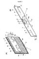
- Fig. 1 is a perspective view showing the drip bag of the first embodiment of the present invention. In (A) of Fig. 1, the drip bag is shown in its completed and before used condition. In (B) of Fig. 1, the holder for supporting the bag is shown in its unfolded flat condition from the reverse side thereof;
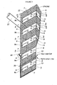
- Fig. 2 is a perspective view showing the process for manufacturing the drip bag of Fig. 1 in which the holders are bonded sequentially to the bag sheet;
- Fig. 3 is a perspective view showing the processes for completing the drip bag following the process shown in Fig. 2;
- Fig. 4 is a perspective view showing the method for using the drip bag of Fig. 1, wherein the inwardly folding portion is pushed into the space defined between the pair of holder halves;
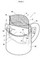
- Fig. 5 is a perspective view showing the drip bag placed on the cup after opened the opening for pouring boiling water;
- Fig. 6 is a perspective view showing the drip bag of the second embodiment of the present invention. In (A) of Fig. 6, the drip bag is shown in its completed and before used condition. In (B) of Fig. 6, in which the turn-in area is pushed inwardly into the space defined between the pair of holder halves;
- Fig. 7 is a perspective view showing the drip bag of the third embodiment of the present invention. In (A) of Fig. 7, the drip bag is shown in its completed and before used condition. In (B) of Fig. 7, the holder for supporting the bag is shown in its unfolded flat condition from the reverse side thereof;
- Fig. 8 is a perspective view showing the drip bag placed on the cup after folded and risen from the drip bag of Fig. 7; and
- Fig. 9 is a perspective view showing the drip bag of on-the-cup type of the prior art. In (A) of Fig. 9, the drip bag is shown in its completed and before used condition. In (B) of Fig. 9, the drip bag is shown in used condition.
-
- The illustrated embodiments are those of the present invention applied to the drip bag for brewing coffee.
- The
drip bag 1 in accordance with the first embodiment and the method for making the same are illustrated in Figs. 1 to 5. - The
drip bag 1 includes afilter bag 3 containing a dose of ground coffee and aholder 5 for supporting the bag. Thefilter bag 3 is provided in a sealed form by an envelope made of the material of gas impermeability (not shown). - Before raised or unfolded, the
holder 5 assumes the shape folded in two with interposing thefilter bag 3 therebetween. Theholder 5 and thefilter bag 3 are bonded with each other in two points. - The
filter bag 3 is formed in a shape of elongate flat pouch. The bag is formed by folding a bag sheet in two to produce afold corner 3a and sealing along the remaining three edges in layers. The bag sheet is preferably of any material, if it is of compliant, liquid permeable, and heat sealable by for example means of the ultrasonic sealing technique. The one of the preferred materials is a non-woven fabric of nylon material with a weigh of 30 g/cm2. Thefilter bag 3 is also provided with a cut offline 3d such as the perforated line extending in parallel with and close to theupper sealing corner 3b. The filter bag is adapted to be opened by cutting it off along theline 3d and remove the portion above the line. Thus, theopening 29 for pouring boiled water into the filter bag is formed. - The ground coffee can be supplied into the
filter bag 3 by the bag-making and supply system. - The
holder 5 is formed by folding an elongate paperboard strip in two around a fold overline 6 to provide a pair of symmetrical holder halves 7. The unfolded flat configuration of theholder 5 seen from the reverse side thereof is illustrated in Fig. 1(B). The transverse length of eachholder half 7 is slightly shorter than that of thefilter bag 3, and the vertical length of eachholder half 7 is slightly smaller than half of that of thefilter bag 3. - In the following description, an expression "folding outwardly" means the situation in which the
holder 5 is folded in two around the fold overline 6 and the fold overline 6 makes a ridgeline on the outer surface. - The end portion of the
holder half 7 extending from the opposite side to the fold overline 6 side to the middle of the half is provided with acut line 8 separating the end portion into upper and lower parts. The upper part will form anarm 9. Therefore, thearm 9 is connected to the remaining portion of theholder half 7 at the terminal end of the cut line, or has the shoulder on the fold overline 6 side. - The
cut line 8 turns its direction twice near the opposite side to make a L-shape line. The L-shape line defines acatch pawl 9a extending downwardly from the free end of thearm 9. - The
holder 5 is also provided across the fold overline 6 thereof with acut line 10 of an inverted "Ω" shape. The total transverse length of thecut line 10 is substantially 1/6 of the total transverse length of theholder 5. Thecentral portion 10a of thecut line 10 is positioned lower. The vertical level of the remaining portion of thecut line 10 is substantially the same as that of thecut line 8. There are tworidge-fold lines 11, extending downwardly from the ends of thecut line 10. The tworidge-fold lines 11 and thecut line 10 define a turn-inarea 13. The portion above the turn-inarea 13 will make a protrudingportion 15. The protruding portion15 includes acatch pawl 15a surrounded by thecentral portion 10a. - The straightly extended portions of the
cut line - The holder halves 7 of thus formed
holder 5 hold thefilter bag 3 therebetween with overlapping the fold overline 6 thereof on thefold corner 3a of thefilter bag 3. Theholder 5 and thefilter bag 3 are bonded with each other by any adhesive applied on a reverse side of the holder except for the area of thearms 9. The precise positions on which the adhesive is applied are illustrated in Fig. 1 (B) by thereference numerals 17, i.e. positions near the fold overline 6 above the line-on-the-cup L and positions immediately below the catch pawls of the arms. - The
holder 5 is attached to thefilter bag 3 so that the fold overline 6 overlaps with the fold backcorner 3a. Theholder 5 is adjusted, vertical direction, not to hide the cut offline 3d. In the example illustrated in Fig. 1, theholder 5 is disposed and bonded at the position relatively close to the cut offline 3d, i.e. the position of the holder with respect to the filter is relatively high. - In the
holder 5 of the structure as mentioned above, thearms 9 can be raised with respect to the remaining portion of the holder, and the turn-inarea 13 can be pushed inwardly into the space defined between the pair of holder halves 7. - The
drip bag 1 according to the present invention has the structure as described above. - The method for manufacturing the
drip bag 1 according to the present invention will now be described with reference to Figs. 2 and 3. - The
reference numeral 21 denotes a bag sheet for forming thefilter bags 3. The bag sheet has a form of elongate tape of the width equal to the twice of the transverse length of the filter bag to be formed. The tape can be withdrawn continuously from a supply reel (not shown). - Desired characters or figures are adapted to be printed on the
holder 5. Theholders 5 are provided by stamping to a predetermined configuration including the fold overline 6, thecut lines holders 5. Theholders 5 are bonded on thebag sheet 21 on regular intervals. The formed holder-sheet assembly is shown in Fig, 2. In this configuration, eachholder 5 has not been folded over. The unfold folder are bonded to thebag sheet 21 under the condition that the longitudinal direction of thereof extends in parallel with the direction of the width of thebag sheet 21, and the position of the folded overline 6 thereof corresponds with the virtualcentral line 21a of thebag sheet 21. - The formed holder-sheet assembly will then run through a sleeve-forming apparatus (not shown). Upon passing through the apparatus, the holder-sheet assembly is folded in two by means of a guide member of the apparatus to lay one side edge of the bag sheet on top of the other as shown in Fig. 3, then thus superposed side edges of the bag sheet are heat sealed with each other by means of a
heated roller 23. As can be seen from the above, the fold over operation is done around thecentral line 21a so that the virtualcentral line 21a will form thefold corner 3a of thefilter bag 3. Sealing the s in layers by theheated roller 23 produces a sealedcorner 3c(see Fig. 1). The sealing operation may be effected by any means other than the heat seal, for example, ultrasonic seal. - The holder-sheet assembly formed into sleeve shape is then sealed and cut by a seal-and-cut mechanism (not shown) being positioned downstream of the sleeve forming apparatus. The cutting operation is adapted to be effected to bisect the sealed area. The lower half of the cut sealed area define an upper sealed
corner 3b, and the upper half of the cut sealed area define a lower sealedcorner 3b'. In other words, the seal-and-cut operation is effected sequentially on an area, which will made the upper sealedcorner 3b and the lower sealedcorner 3b'. Upon cutting, a product is separated under conditions that the three edges in layers have been closed. Simultaneously, a sealed corner is made, which will make the lower sealedcorner 3b' of anext holder 5 - If it is intended to obtain a series of drip bags connected with each other, only the sealing operation may be done without cutting.
- The process head for the seal-and-cut operation has integrally an apparatus for forming a perforated line, or a perforator positioned by the side of the traveling direction of the bag sheet. The cut off
line 3d of thefilter bag 3 is made by the perforator - The
reference numeral 27 denotes a filling nozzle extending from a coffee hopper (not shown). The nozzle extends from a position proximal to the sleeve forming apparatus and the tip thereof is adapted to be positioned within a sleeve of thebag sheet 21 as being formed by the sleeve forming apparatus for delivering a predetermined amount of ground coffee. After one seal-and-cut operation has been completed to form a sleeve with the lower corner, the delivery is done and thereafter a next seal-and-cut operation is made. Thus, a drip bag is made and simultaneously an amount of coffee is filled into the drip bag. - As can be seen from the above, the
drip bag 1 with theholder 5 being bonded thereto, can be obtained with the coffee being filled therein. - The method for using the
drip bag 1 will now be described. - At first, the turn-in
area 13 of theholder 5 is pushed inwardly into the space defined between the pair ofholder halves 7 as shown in Fig. 4. This operation may be effected by inserting a finger between the turn-inarea 13 and thefilter bag 3 to open the holder halves 7in V-shape, and thereafter pushing by another finger the middle of the turn-in area 13 (or the fold over line 6) inwardly into the space between thehalves 7 to invert the V-shape. The turn-inarea 13 sustains the V-shape thereof by the rigidity of the material of theholder 5 unless any external forces to fold it flat are applied intentionally thereto. In other words, the turn-inarea 13 is served as a brace generating a force for keeping theholder halves 7 separated from each other. Thus, theholder halves 7 are bend outwardly in the opposite direction. Further, the protrudingportion 15 extends outwardly from the remaining portion of theholder 5. - The upper sealed
corner 3b is then opened by cutting thefilter bag 3 along the cut offline 3d as shown by the alternate long and two short dashes line in Fig. 4 to make theopening 29 for pouring boiled water. Theopening 29 of thefilter bag 3 is widened by opening theholder halves 7 from each other under the effect of the force provided by the inwardly foldedportion 13. Thearms 9 are also get away from each other to assume V-shape since these arms are not adhered to thefilter bag 3. - If it is intended to make a coffee extrude in a
cup 30, the folded V-shapedholder 5 is placed on the rim of thecup 30. That is to say, the pair ofarms 9 and the protrudingportion 15 is placed on the rim with disposing the lower portion of thefilter bag 3 within thecup 30. In this connection, theholder 5 is disposed over thecup 30 with suspending thefilter bag 30 therefrom, and the portion of theholder 5 extending downwardly from the line-on-the-cup L is disposed within thecup 30 with holding thefilter bag 3. The position of thearms 9 and the protrudingportion 15 on the cup depend on the size of thecup 30. However, in any case, the holder can be placed very stably on the cup since theholder 5 is supported by three points provided by thearms 9 and the protrudingportion 15. The shift movement and the falling-off of thedrip bag 1 can surely be avoided because the portion of theholder 5 extending downwardly from the line-on-the-cup L falls within thecup 30 and thecatch pawls 9a of thearms 9 and thecatch pawls 15a of the protrudingportion 15 are engaged with the rim of thecup 30. - As shown in Fig. 5, substantially whole of the
drip bag 3 is included within the boundary defined by the side wall of thecup 30 when thedrip bag 1 is placed on thecup 30. Thefilter bag 3 completely falls within the boundary, and major volume of theholder 5 does not extend outwardly from thecup 30. - If it is intended to open the
opening 29 wider, or to increase the angle of the V defined by thearms 9, it might be better to deform theholder halves 7 intentionally at about the middle portion thereof so as to approach the shape of theholder 5 extending downwardly from the line-on-the-cup L to a circle. - If using a cup of smaller size, the free ends or the distal ends of the holder extending downwardly from the line-on-the-cup L are superposed to diminish the portions extending downwardly from the line-on-the-cup L, so that the drip bag can be used for the cup of the inner diameter of 5 cm.
- In the
drip bag 1 described above with reference to the drawings, theholder 5 is attached to thefilter bag 3 in the high position, i.e. the position near the cut offline 3d, so that the distance from the line-on-the-cup L to the bottom end of thefilter bag 3 is relatively large. In thedrip bag 1 of this type, the bottom portion of thefilter bag 3 is adapted to be immersed within an extracting liquid. In other words, thedrip bag 1 is of the type suitable for steeping method. - If it is intended to alter the type of the drip bag to the so-called drip on type in which the filter bag is not immersed in the extracted liquid collected in the cup, it might be better to shift the position of the
holder 5 on thefilter bag 3 to approach the bottom of the filter. For example, theholder 5 may be bonded in the position illustrated in Fig. 1(A) in which the line-on-the-cup L is shifted to the position designated by the alternate long and two short dashes line L. - The position of the
holder 5 on thefilter bag 3 can be altered by shifting the bonding phase of the holders and thebag sheet 21 along the running direction or by bring the seal-and-cut position close to theholder 5. - The
drip bag 1A of the second embodiment of the present invention is illustrated in Fig. 6. Thedrip bag 1A is substantially identical with thedrip bag 1 except for the arms and the vertical length of the folder. Considering this connection, the following description of thedrip bag 1A is directed only to the arms. The remaining portions or elements are denoted by the same reference numeral with prime or alphabetical symbols in order to avoid the duplication. The identical prime or alphabetical symbols are also used in a third embodiment. - The vertical length of the
holder 5A of thedrip bag 1A is about 2/3 of the vertical length of thefilter bag 3 defined by the upper and lower corners of thefilter bag 3. On the opposite side to the fold overline 6 side, there is acut line 35 of substantially "U" shape for defining anarm 9A. Thearm 9A includes acatch pawl 9a'. Theholder 5A is bonded to thefilter bag 3 at the protrudingportion 15 and the marginal portion around thearm 9A. - In such a configuration, the
filter bag 3 can be held stationary after theopening 29 is formed for pouring boiled water since the major part of thefilter bag 3 can be held by theholder 5. - The
drip bag 1 B of the third embodiment of the present invention is illustrated in Figs. 7 and 8. The only difference between thedrip bag 1 and thedrip bag 1B is that the holder portion which is lower than the line-on-the-cup L, can be assembled to provide an endless loop. - The portion the holder lower than the line-on-the-cup L is defined by a transversely extending "U" shaped cut
line 41. Thecut line 41 has two ends positioned on the opposite side. The area defined by thecut line 41 will form a connectingpiece 43. The connectingpiece 43 is continuous with the holder at the distal end of theholder 5. The connectingpiece 43 is provided with twocutout lines 43a. The length of thecutout line 43a is half of the vertical length of thepiece 43. Thecutout line 43a is positioned on the free end side. One of thecutout line 43a extends from the upper end of the connectingpiece 43 and the other from the lower end thereof. - When it is intended to use the
drip bag 1B, the connectingpieces 43 of the holder halves are raised and connecting with each other by mating thecut lines 43a. Thus, theholder halves 7 are connected with each other to define an endless loop of the holder for holding thefilter bag 3, so that thefilter bag 3 can be held very stably by means of theholder 5B. In addition, the pieces connected with each other will generate a force tend to open the opening defined by the holder, so that the shape of theholder 5 will approach the circular configuration, and thus the opening for pouring boilingwater 29 may be enlarged. - While particular embodiments of the present invention have been illustrated and described, it should be obvious to those skilled in the art that various changes and modifications can be made without departing from the spirit and scope of the invention.
- For example, the drip bag of the present invention can be applied for brewing or extracting any suitable materials other than coffee.
- The drip bag of the present invention includes a holder of simpler structure folded over itself rather than the cylindrical one. Nevertheless, the holder presents a portion to be accommodated within the cup and three portions to be rested on the rim of the cup. Thus, the drip bag can be maintained on the cup stably and the opening of the filter bag can be enlarged sufficiently.
- The drip bag of the present invention can be filled at the same time with the forming phase of the bag.
Claims (6)
- A drip bag comprising:wherein the holder includes two arms and a turn-in area and is bonded to the filter bag at the other portion than the arms,a filter bag containing a material to be extracted therein, having upper, lower and two side corners with no opening, and having a cut off line for breaking made along the upper corner, anda holder being of a paper material body and before being unfolded, being folded in two and surrounding the filter bag so that the fold over line overlaps one of the side corners,
each arm being made of an upper portion of the paper material body, has a shoulder on the fold over line side and a free end on the opposite side,
the turn-in area being defined by a cut line extending across the fold over line and two fold lines, respectively, extending from the ends of the cut line downwardly. - A drip bag according to claim 1, wherein the filter bag is formed by folding a rectangular bag sheet therefor in two and sealing three pairs of the edges in layers to produce three sealed corner and one fold corner, and the holder surrounds the filter bag so that the fold over line overlaps the fold corner.
- A drip bag according to claim 2, wherein the vertical length of the holder is substantially equal to or smaller than the half of the vertical length of the filter bag.
- A drip bag according to any one of claims 1 to 3, wherein each arm of the holder includes a catch pawl extending downwardly from the free end thereof, and the vertical height of the cut line of the turn-in area is lower at an intermediate portion across the fold over line than at the remaining portions.
- A drip bag according to any one of claims 1 to 4, further including a pair of connecting pieces, each of which is made of a portion of the paper material below the arm, has the shoulder on the opposite side and the free end on the fold over line side, and has an engaging means for matching the two pieces on the free end side.
- A method for making a drip bag comprising the steps of:wherein the holder includes two arms and a turn-in area,providing a liquid permeable long, bag sheet,providing a holder being of a paper material body and having a fold over line, along which the holder will be folded,
each arm has the shoulder on the fold over line side and the fee end on the opposite side,
the turn-in area being defined a cut line extending across the fold over line and two fold lines, respectively, extending from the ends of the cut line downwardly,
traveling the bag sheet,
bonding to the traveling bag sheet, the holders by an adhesive, which has been applied to the holder at a portion other than the arms, on regular intervals so as to align the fold over line with the longitudinal central line of the sheet,
folding the holder together with the bag sheet along the fold over line,
sealing the edges in layers to form a sleeve,
supplying a material to be extracted into the sleeve, and
sealing the sleeve between the adjacent holders, whereby the material is packed into the filter bag.
Applications Claiming Priority (2)
| Application Number | Priority Date | Filing Date | Title |
|---|---|---|---|
| JP2002188233 | 2002-06-27 | ||
| JP2002188233A JP3947052B2 (en) | 2002-06-27 | 2002-06-27 | Drip bag and drip bag manufacturing method |
Publications (2)
| Publication Number | Publication Date |
|---|---|
| EP1375384A2 true EP1375384A2 (en) | 2004-01-02 |
| EP1375384A3 EP1375384A3 (en) | 2004-07-28 |
Family
ID=29717652
Family Applications (1)
| Application Number | Title | Priority Date | Filing Date |
|---|---|---|---|
| EP03251006A Withdrawn EP1375384A3 (en) | 2002-06-27 | 2003-02-19 | A drip bag |
Country Status (3)
| Country | Link |
|---|---|
| EP (1) | EP1375384A3 (en) |
| JP (1) | JP3947052B2 (en) |
| TW (1) | TWI270509B (en) |
Cited By (1)
| Publication number | Priority date | Publication date | Assignee | Title |
|---|---|---|---|---|
| CN108135387A (en) * | 2015-06-25 | 2018-06-08 | 贡萨洛·费莉佩·利亚奇维拉洛博斯 | Disposable filter cylinder as filter, particularly for the brewed filter of the soluble component of fragrant plant such as tealeaves, coffee, camomile etc. |
Families Citing this family (8)
| Publication number | Priority date | Publication date | Assignee | Title |
|---|---|---|---|---|
| KR100552044B1 (en) * | 2004-05-14 | 2006-02-20 | 정경석 | Tea bag |
| JP5019034B2 (en) * | 2007-03-19 | 2012-09-05 | 大紀商事株式会社 | Drip bag |
| JP4312819B2 (en) | 2008-01-22 | 2009-08-12 | 株式会社神戸製鋼所 | Aluminum alloy sheet with excellent ridging marks during molding |
| JP5894740B2 (en) * | 2011-03-09 | 2016-03-30 | 不双産業株式会社 | Extraction bag |
| JP2012143592A (en) * | 2012-03-28 | 2012-08-02 | Daiki Shoji Kk | Drip bag |
| WO2020037605A1 (en) * | 2018-08-23 | 2020-02-27 | 林紫绮 | Clip-type beverage brewing structure that does not release toxic substances |
| JP7224673B2 (en) | 2020-11-20 | 2023-02-20 | 株式会社W | Simple coffee extractor bag and simple coffee extractor pack |
| WO2024024809A1 (en) * | 2022-07-26 | 2024-02-01 | 山中産業株式会社 | Beverage extraction filter and beverage extraction bag |
Citations (8)
| Publication number | Priority date | Publication date | Assignee | Title |
|---|---|---|---|---|
| EP0401951A1 (en) * | 1989-06-07 | 1990-12-12 | Japan I.P. Co. Ltd. | Filter device |
| JPH06113952A (en) * | 1991-06-09 | 1994-04-26 | Yamanaka Sangyo Kk | Drink for taste and filter for seasoning |
| JPH07287A (en) * | 1993-06-03 | 1995-01-06 | Fuso Sangyo Kk | Packaging body |
| JPH10165309A (en) * | 1996-12-10 | 1998-06-23 | Kataoka Bussan Kk | Filtering device for coffee, tea, etc. |
| JPH10234575A (en) * | 1997-02-28 | 1998-09-08 | Shozo Nakajima | Coffee dripper |
| JP2000201823A (en) * | 1999-01-19 | 2000-07-25 | Key Coffee Inc | Luxury beverage extraction bag with cup mounted type supporter |
| WO2001056439A1 (en) * | 2000-01-31 | 2001-08-09 | Michiko Sakamoto | Support-equipped extraction bag, extraction-subject material containing support-equipped extraction bag, and sheet complex for producing the same |
| JP2002238767A (en) * | 2001-02-20 | 2002-08-27 | Saeko Onda | Extraction bag with support tool, extraction bag with support tool for storing extracted material, and sheet composite body for producing bags |
-
2002
- 2002-06-27 JP JP2002188233A patent/JP3947052B2/en not_active Expired - Lifetime
-
2003
- 2003-02-11 TW TW92102784A patent/TWI270509B/en not_active IP Right Cessation
- 2003-02-19 EP EP03251006A patent/EP1375384A3/en not_active Withdrawn
Patent Citations (8)
| Publication number | Priority date | Publication date | Assignee | Title |
|---|---|---|---|---|
| EP0401951A1 (en) * | 1989-06-07 | 1990-12-12 | Japan I.P. Co. Ltd. | Filter device |
| JPH06113952A (en) * | 1991-06-09 | 1994-04-26 | Yamanaka Sangyo Kk | Drink for taste and filter for seasoning |
| JPH07287A (en) * | 1993-06-03 | 1995-01-06 | Fuso Sangyo Kk | Packaging body |
| JPH10165309A (en) * | 1996-12-10 | 1998-06-23 | Kataoka Bussan Kk | Filtering device for coffee, tea, etc. |
| JPH10234575A (en) * | 1997-02-28 | 1998-09-08 | Shozo Nakajima | Coffee dripper |
| JP2000201823A (en) * | 1999-01-19 | 2000-07-25 | Key Coffee Inc | Luxury beverage extraction bag with cup mounted type supporter |
| WO2001056439A1 (en) * | 2000-01-31 | 2001-08-09 | Michiko Sakamoto | Support-equipped extraction bag, extraction-subject material containing support-equipped extraction bag, and sheet complex for producing the same |
| JP2002238767A (en) * | 2001-02-20 | 2002-08-27 | Saeko Onda | Extraction bag with support tool, extraction bag with support tool for storing extracted material, and sheet composite body for producing bags |
Non-Patent Citations (6)
| Title |
|---|
| PATENT ABSTRACTS OF JAPAN vol. 018, no. 395 (C-1229), 25 July 1994 (1994-07-25) -& JP 06 113952 A (YAMANAKA SANGYO KK;OTHERS: 01), 26 April 1994 (1994-04-26) * |
| PATENT ABSTRACTS OF JAPAN vol. 1995, no. 04, 31 May 1995 (1995-05-31) -& JP 07 000287 A (FUSO SANGYO KK), 6 January 1995 (1995-01-06) * |
| PATENT ABSTRACTS OF JAPAN vol. 1998, no. 11, 30 September 1998 (1998-09-30) -& JP 10 165309 A (KATAOKA BUSSAN KK), 23 June 1998 (1998-06-23) * |
| PATENT ABSTRACTS OF JAPAN vol. 1998, no. 14, 31 December 1998 (1998-12-31) -& JP 10 234575 A (NAKAJIMA SHOZO), 8 September 1998 (1998-09-08) * |
| PATENT ABSTRACTS OF JAPAN vol. 2000, no. 10, 17 November 2000 (2000-11-17) -& JP 2000 201823 A (KEY COFFEE INC;YAMANAKA SANGYO KK), 25 July 2000 (2000-07-25) * |
| PATENT ABSTRACTS OF JAPAN vol. 2002, no. 12, 12 December 2002 (2002-12-12) -& JP 2002 238767 A (ONDA SAEKO), 27 August 2002 (2002-08-27) * |
Cited By (2)
| Publication number | Priority date | Publication date | Assignee | Title |
|---|---|---|---|---|
| CN108135387A (en) * | 2015-06-25 | 2018-06-08 | 贡萨洛·费莉佩·利亚奇维拉洛博斯 | Disposable filter cylinder as filter, particularly for the brewed filter of the soluble component of fragrant plant such as tealeaves, coffee, camomile etc. |
| EP3315055A4 (en) * | 2015-06-25 | 2019-04-17 | Llach Villalobos, Gonzalo Felipe | Disposable cartridge for use as a filter, in particular for the infusion of soluble elements, aromatic herbs such as tea, coffee, chamomile, etc. |
Also Published As
| Publication number | Publication date |
|---|---|
| JP3947052B2 (en) | 2007-07-18 |
| EP1375384A3 (en) | 2004-07-28 |
| TW200400145A (en) | 2004-01-01 |
| TWI270509B (en) | 2007-01-11 |
| JP2004024700A (en) | 2004-01-29 |
Similar Documents
| Publication | Publication Date | Title |
|---|---|---|
| CN102046050B (en) | Drip bag | |
| US6105821A (en) | Dispensing container for highly viscous liquids | |
| EP0733015B1 (en) | A method for manufacturing packages for liquid products, especially liquid foodstuffs, a package obtained through this method | |
| EP0442299B1 (en) | Flexible pouch with folded spout | |
| US3186625A (en) | Bags for milk and the like | |
| US5059325A (en) | Tubular coffee filter with vertical fold lines | |
| EP1375384A2 (en) | A drip bag | |
| US6733804B1 (en) | Multi-chambered infusion bag, especially for tea | |
| JP4061184B2 (en) | Dripper | |
| JP4024062B2 (en) | Drip bag and drip bag manufacturing method | |
| CA1294790C (en) | Filter, especially coffee filter, and process for producing it | |
| JPH09183442A (en) | Packing bag for liquid food | |
| JP4882188B2 (en) | Dripper | |
| RU2196090C2 (en) | Package for loose products | |
| JP4124352B2 (en) | Dripper | |
| JP5046847B2 (en) | Taste beverage extraction bag with cup-mounted support and extraction method | |
| JPWO2009078090A1 (en) | Packaging bag | |
| JP4531544B2 (en) | Dripper | |
| JP3967258B2 (en) | Dripper | |
| JP4043908B2 (en) | Drip bag | |
| JP4061176B2 (en) | Dripper | |
| JPS61115836A (en) | Fluid vessel | |
| CN217477953U (en) | Reusable food packaging bag | |
| JP4061177B2 (en) | Dripper | |
| JP2003038355A (en) | Extraction tool and method for manufacturing the same |
Legal Events
| Date | Code | Title | Description |
|---|---|---|---|
| PUAI | Public reference made under article 153(3) epc to a published international application that has entered the european phase |
Free format text: ORIGINAL CODE: 0009012 |
|
| AK | Designated contracting states |
Kind code of ref document: A2 Designated state(s): AT BE BG CH CY CZ DE DK EE ES FI FR GB GR HU IE IT LI LU MC NL PT SE SI SK TR |
|
| AX | Request for extension of the european patent |
Extension state: AL LT LV MK RO |
|
| PUAL | Search report despatched |
Free format text: ORIGINAL CODE: 0009013 |
|
| AK | Designated contracting states |
Kind code of ref document: A3 Designated state(s): AT BE BG CH CY CZ DE DK EE ES FI FR GB GR HU IE IT LI LU MC NL PT SE SI SK TR |
|
| AX | Request for extension of the european patent |
Extension state: AL LT LV MK RO |
|
| RIC1 | Information provided on ipc code assigned before grant |
Ipc: 7B 65B 9/20 B Ipc: 7B 65B 9/02 B Ipc: 7B 65D 81/00 A |
|
| 17P | Request for examination filed |
Effective date: 20050117 |
|
| AKX | Designation fees paid |
Designated state(s): DE FR GB NL |
|
| GRAP | Despatch of communication of intention to grant a patent |
Free format text: ORIGINAL CODE: EPIDOSNIGR1 |
|
| STAA | Information on the status of an ep patent application or granted ep patent |
Free format text: STATUS: THE APPLICATION IS DEEMED TO BE WITHDRAWN |
|
| 18D | Application deemed to be withdrawn |
Effective date: 20070523 |