EP0186820B2 - Method and apparatus to determine the weight of a quantity of material, e.g. refuse, by emptying a receptacle into a collecting vehicle - Google Patents
Method and apparatus to determine the weight of a quantity of material, e.g. refuse, by emptying a receptacle into a collecting vehicle Download PDFInfo
- Publication number
- EP0186820B2 EP0186820B2 EP85115743A EP85115743A EP0186820B2 EP 0186820 B2 EP0186820 B2 EP 0186820B2 EP 85115743 A EP85115743 A EP 85115743A EP 85115743 A EP85115743 A EP 85115743A EP 0186820 B2 EP0186820 B2 EP 0186820B2
- Authority
- EP
- European Patent Office
- Prior art keywords
- container
- weighing
- emptying
- collecting vehicle
- accordance
- Prior art date
- Legal status (The legal status is an assumption and is not a legal conclusion. Google has not performed a legal analysis and makes no representation as to the accuracy of the status listed.)
- Expired - Lifetime
Links
Images
Classifications
-
- B—PERFORMING OPERATIONS; TRANSPORTING
- B65—CONVEYING; PACKING; STORING; HANDLING THIN OR FILAMENTARY MATERIAL
- B65F—GATHERING OR REMOVAL OF DOMESTIC OR LIKE REFUSE
- B65F3/00—Vehicles particularly adapted for collecting refuse
- B65F3/02—Vehicles particularly adapted for collecting refuse with means for discharging refuse receptacles thereinto
- B65F3/04—Linkages, pivoted arms, or pivoted carriers for raising and subsequently tipping receptacles
- B65F3/041—Pivoted arms or pivoted carriers
- B65F3/043—Pivoted arms or pivoted carriers with additional means for keeping the receptacle substantially vertical during raising
- B65F3/045—Four-bar linkages
-
- B—PERFORMING OPERATIONS; TRANSPORTING
- B65—CONVEYING; PACKING; STORING; HANDLING THIN OR FILAMENTARY MATERIAL
- B65F—GATHERING OR REMOVAL OF DOMESTIC OR LIKE REFUSE
- B65F3/00—Vehicles particularly adapted for collecting refuse
- B65F3/02—Vehicles particularly adapted for collecting refuse with means for discharging refuse receptacles thereinto
- B65F2003/022—Vehicles particularly adapted for collecting refuse with means for discharging refuse receptacles thereinto the discharging means comprising a device for determining the weight of the content of refuse receptacles
Definitions
- the invention relates to a method and a device for recording the weight of material entered into a container, preferably domestic waste, in which the container is inserted into the container receptacle of the emptying device of a collecting vehicle and is emptied into the collecting vehicle by swiveling it up and overhead.
- the waste disposal of companies and municipalities is causing increasing problems due to the large amount of waste generated, among other things because of the landfill areas that are no longer available to a sufficient extent and because of the environmental pollution that occurs during landfill but also incineration.
- the aim is to reduce the amount of waste generated.
- the heterogeneous, constantly changing composition of waste does not yet allow an economical way of fractioning into usable individual substances. Landfilling and incineration of unsorted waste are currently considered state of the art.
- This proposal essentially serves to control the emptying process itself and possibly also the containers via the programming and switching device and, if necessary, to influence the control of the emptying device accordingly.
- the document does not contain any indication of how the weighing process should proceed as such.
- the invention has for its object to make a household-specific weighing of the garbage that is integrated into the process of emptying the garbage into the collecting vehicle, such that the conventional sequence of the emptying process and the construction of the conventional emptying device of the collecting vehicle are only slightly changed and, on the other hand, accurate and fastest possible weighing with simultaneous determination of the empty weight of the containers including registration of all data can be carried out.
- an identification element arranged on the container is brought into operative connection with a sensor detection element arranged on the emptying device and a household identification signal is fed to a registration and storage device, the container is lifted and in this position by a relative movement due to weight of the container receptacle and the other emptying device weighing weighing device (first weighing), the container is pivoted further up and emptied and swung back into the raised position and weighed again in this position (second weighing), the weighing processes being timed by position indicators and the determined weight signals of the registration and storage device are supplied and the container is lowered for removal.
- This procedure enables the gross weight of the filled container and the tare weight of the emptied container to be determined during the emptying of the container carried out by the emptying device of a collecting vehicle.
- An advantage of the invention is therefore that the weighing process is integrated in the emptying process of the containers. If the method is carried out in such a way that the emptying device is stopped during the first weighing and during the second weighing, the use of modern weighing electronics results in only very short downtimes of a few seconds, which are only insignificant from a cost point of view, considering the total emptying process influence.
- the measuring signals are transmitted to a computing and recording device in the driver's cab by means of measuring amplifiers Transferred vehicle.
- the weight signals are processed in this processor unit and the calculated net weight of the container contents is fed to a magnetic tape unit as a data memory.
- each waste container requires a coded identifier, which in turn is "read" by a recognition unit located on the receiving plate of the emptying device, which is also referred to as a bed.
- This detection signal is also stored on the magnetic tape via the computing unit. If necessary, the registered control data can be printed out immediately.
- Another advantage of the invention is that the container weight is measured using the weight-related relative movements between the container receptacle and the other emptying device, namely the lifting swivel device. It is thereby achieved that only the - constant - weights of the container receptacle, which are small in relation to the other parts of the emptying device, flow into the weight measurement. As a result, the influence of the inertial forces occurring during the execution of the swiveling movements is kept as small as possible, as a result of which the weighing device can be made relatively simple and therefore inexpensive and nevertheless very good measurement results are achieved.
- the method is advantageously designed so that it runs almost completely automatically; in particular, the weighing processes are time-controlled by position indicators.
- the weighing device provided for weighing can be automatically unlocked before each weighing process and automatically locked after each weighing process.
- the weighing device can give control pulses to the emptying device for the automatic initiation of the subsequent method steps. If the container is not identified, for example if the operative connection between the identification element arranged on the container and the sensor detection element has not been established, the hydraulic system of the emptying device can be automatically blocked and a signal can be given by which the operator is made aware of the error.
- the method as a whole can thus be designed in such a way that the operator only has to operate one main control valve and the internal circuit logic of the control prevents the vessel from being emptied without identification and weighing process.
- a collecting vehicle for carrying out the above-mentioned method which has an emptying device for emptying material, preferably domestic waste, into the collecting vehicle, the emptying device having a container holder and a lifting and pivoting device for the container holder, a sensor recognition element for recognizing an identification element of the container is arranged on the emptying device thereof, the collecting vehicle having a registration and storage unit which can be supplied with a household identification signal by the identification element, and wherein a weighing device is arranged between the container receptacle and the lifting and pivoting device which gives the weight signals to the registration and storage device.
- this design has the peculiarity that the integrated weighing device is arranged as far forward as possible within the emptying device towards the container, which results in the advantages of the simple construction and the high measuring accuracy.
- the weighing device can be designed as a structural unit that can be integrated as an additional component or retrofit kit in the known emptying devices (fillings) of the collecting vehicles.
- This has the advantage that the known emptying devices in the new production only have to be slightly modified in terms of design to adapt to the invention.
- This has the further advantage that the weighing device can be installed as a retrofit kit in the bed of collecting vehicles already in use. This finally has the advantage that the removal and installation for repair purposes is facilitated.
- the device can be developed in such a way that the container receptacle is connected to a vertically displaceable sliding piece which is arranged in the weighing device and is operatively connected to a measuring cell, and that a device is provided for locking the sliding piece.
- the slider can be designed as a rod body which can be displaced in a tube and which in turn can be operatively connected to a measuring cell arranged in the tube.
- the tube is preferably designed as a support tube that can be integrated into the emptying device and carries all parts of the weighing device.
- the support tube can be connected to the emptying device via parallelogram links which are pivoted by lifting cylinders.
- the device can be retrofitted as an additional component or as a retrofit kit in already existing emptying devices.
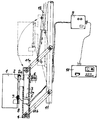
- the device according to the exemplary embodiment is arranged on a known emptying device (filling) of a refuse collection vehicle, with which the refuse containers are emptied into the collection vehicle. Of this bed, only the support and pivot tube 11 projecting downward is shown.
- the carrying and pivoting tube 11 usually has two parallelogram link pairs 11a, 11b articulated thereon, the free ends of which are articulatedly connected to the container receptacle in the known designs.
- the parallelogram link pairs 11a, 11b and thus the container receptacle are pivoted up and down by means of one or more lifting cylinders 12 which engage the upper or lower parallelogram link pairs 11a.
- the weighing device is now arranged at the free ends of the pairs of parallelogram links 11a, 11b instead of the usual container receptacle.
- the weighing device has a vertical support tube 4 articulated to the parallelogram links, in which a sliding body 3 is slidably arranged.
- a support plate 2 a is connected to the sliding body and is led out through an opening in the support tube 4 and is connected to a container receptacle 2.
- an identification plate 7 is fastened so that, when the container is attached to the weighing device, it faces a detection sensor 8 which is integrated in the container receptacle 2.
- a measuring cell 5 is arranged below the sliding body 3, which is in operative connection with the sliding body 3.
- the sliding body 3 has a pin 3a projecting downwards, which acts on the measuring cell 5, which is designed as a piezo element or strain gauge.
- 6 with a arranged on the outside of the support tube 4 locking device is referred to, which has a preferably electromagnetically displaceable locking pin which can be advanced through an opening of the support tube 4 against the sliding body 3, so that the sliding body can be locked against displacement.
- the detection sensor 8 and the measuring cell 5 are electrically connected to a measuring amplifier 9, which in turn is electrically connected to a registration unit 10.
- the registration unit serves to register and store the detection data received by the detection sensor 8 and the weighing data received by the measuring cell 5.
- the device works as follows:
- a container 1 is inserted into the container receptacle 2.
- the detection sensor 8 forwards the detection data received from the identification plate 7 to the registration unit 10 via the measuring amplifier 9. If no detection data is recorded, a signal device assigned to the detection sensor gives a signal so that the operator is made aware of the error. In addition, the hydraulic system of the device is preferably blocked in such a case so that the container cannot be emptied. After the "detection" of the container has taken place, the weighing device is raised by the lifting cylinder 12 into the swiveled-up position shown in broken lines in the drawing.
- the locking device 6 releases the sliding body 3, whereupon the latter transfers the weighing value of the container (gross weight) to the measuring cell 5 with a downward displacement.
- the measuring cell forwards the weighing value via the measuring amplifier 9 to the registration unit 10.
- the locking device 6 then locks the sliding body 3 again, whereupon the emptying process is initiated.
- the emptying process takes place in a known manner in that the carrying and pivoting tube 11 of the bed is pivoted clockwise about an upper pivot point, not shown, by approximately 180 °, whereby the container 1 is emptied into the collecting vehicle. This actual emptying process is preferably controlled by the operator by hand.
- the carrying and pivoting tube 11 is pivoted back into the lower position shown in the drawing, the weighing device with the container initially being in the position shown in broken lines in the drawing.
- the locking device 6 is unlocked and the empty weight of the container (tare weight) is measured by the measuring cell 5, which in turn forwards the measurement data to the registration unit 10.
- the locking device 6 locks the sliding body 3, whereupon the weighing device is swiveled downward into the lower position shown in the drawing by pivoting the parallelogram links 11a, 11b downward, and the container is removed from the container holder 2 by the operator.
- the weighing device is preferably automatically adjusted, for which purpose the locking device 6 releases the sliding body 3 again and then locks it again. Then the device is ready to hold another container.
Abstract
Description
Die Erfindung betrifft ein Verfahren und eine Vorrichtung zum gewichtsmäßigen Erfassen von in einen Behälter eingegebenem Material, vorzugsweise Hausmüll, bei dem der Behälter in die Behälteraufnahme der Entleerungsvorrichtung eines Sammelfahrzeuges eingesetzt und von dieser unter Hoch-und Überkopfschwenken in das Sammelfahrzeug entleert wird.The invention relates to a method and a device for recording the weight of material entered into a container, preferably domestic waste, in which the container is inserted into the container receptacle of the emptying device of a collecting vehicle and is emptied into the collecting vehicle by swiveling it up and overhead.
Die Müllentsorgung von Betrieben und Gemeinden bereitet wegen der großen anfallenden Müllmengen zunehmend Probleme, unter anderem wegen der nicht mehr in ausreichendem Maße zur Verfügung stehenden Deponieflächen und wegen der bei der Deponierung aber auch Verbrennung auftretenden Umweltbelastungen. Anzustreben ist eine Verringerung der anfallenden Müllmengen.The waste disposal of companies and municipalities is causing increasing problems due to the large amount of waste generated, among other things because of the landfill areas that are no longer available to a sufficient extent and because of the environmental pollution that occurs during landfill but also incineration. The aim is to reduce the amount of waste generated.
Pauschalierte Müllentsorgungsgebühren bieten den Betrieben und Bürgern keinen Anreiz zur Verringerung der Müllmengen bzw. zur freiwilligen Sortierung des Mülls und der Rückführung verwertbarer Bestandteile in Nutzungsprozesse.Flat-rate waste disposal fees do not provide companies and citizens with an incentive to reduce the amount of waste or to voluntarily sort the waste and return recyclable components to usage processes.
Eine Verminderung der Gesamtmüllmenge kann nur erwartet werden, wenn den Betrieben und Bürgern eine gerechte Kostenbelastung und die Möglichkeit der Fraktionierung des anfallenden Mülls geboten wird.A reduction in the total amount of waste can only be expected if the companies and citizens are offered a fair cost and the possibility of fractionating the waste generated.
Dem Umweltschutzgedanken wird erst in wenigen Teilbereichen der Entsorgung Rechnung getragen. Speziell auf dem Gebiet des Hausmülls wird nur bei Glas und Altpapier die Möglichkeit gegeben, Wertstoffe dem Recycling zuzuführen.Environmental protection is only taken into account in a few areas of waste disposal. Especially in the field of household waste, only glass and waste paper are given the opportunity to recycle them.
Die heterogene, sich immer stark verändernde Zusammensetzung des Mülls gestattet bis heute noch keine wirtschaftliche Art der Fraktionierung in verwertbare Einzelstoffe. Die Deponierung und die Verbrennung des unsortierten Mülls sind derzeit als Stand der Technik anzusehen.The heterogeneous, constantly changing composition of waste does not yet allow an economical way of fractioning into usable individual substances. Landfilling and incineration of unsorted waste are currently considered state of the art.
Für die Zukunft muß davon ausgegangen werden, daß durch verschärfte umweltrelevante Auflagen die Müllentsorgung stark verteuert wird. Das Wiederverwertungsgebot kann nur durch insbesondere finanzielle Anreize für die Betriebe und Bürger verwirklicht werden. Den Betrieben und Bürgern muß die Möglichkeit geboten werden, die Höhe der Gebühren für die Müllentsorgung selbst beeinflussen zu können. Erst durch diesen Anreiz wird sich im Ergebnis die Müllmenge ganz erheblich verringern, mit den sekundären Effekten der Aufteilung in unterschiedliche Wertstoffe und der Entlastung der Mülldeponien und der Schonung der Umwelt.In the future it must be assumed that waste disposal will become more expensive due to stricter environmental requirements. The recycling requirement can only be realized through financial incentives for companies and citizens. Companies and citizens must be given the opportunity to influence the level of waste disposal fees themselves. Only through this incentive will the amount of waste be reduced significantly, with the secondary effects of the division into different recyclables and the relief of the landfills and the protection of the environment.
Nach dem nicht vorveröffentlichten Dokument WO 85/03689 ist bereits die Möglichkeit vorgeschlagen worden, Behälter vor und nach dem Entleerungsvorgang zu wiegen, um den Behälterinhalt festzustellen und zusammen mit Erkennungsangaben in eine Programmier- und Schaltvorrichtung einzulesen, an die wieder eine zusätzliche Registrier- und Aufzeichnungseinrichtung angeschlossen ist.According to the document WO 85/03689, which has not been published beforehand, the possibility has already been proposed of weighing containers before and after the emptying process, in order to determine the contents of the container and to read it together with identification information into a programming and switching device to which an additional registration and recording device is again connected connected.
Dieser Vorschlag dient im wesentlichen dazu, über die Programmier- und Schaltvorrichtung den Entleerungsvorgang selbst und gegebenenfalls auch die Behälter zu kontrollieren und bei Bedarf die Steuerung der Entleerungsvorrichtung entsprechend zu beeinflussen. Einen Hinweis darauf, wie der Wiegevorgang als solcher im einzelnen ablaufen soll, enthält das Dokument nicht.This proposal essentially serves to control the emptying process itself and possibly also the containers via the programming and switching device and, if necessary, to influence the control of the emptying device accordingly. The document does not contain any indication of how the weighing process should proceed as such.
Der Erfindung liegt die Aufgabe zugrunde, eine haushaltsspezifische Wiegung des anfallenden Mülls vorzunehmen, die in den Ablauf der Entleerung des Mülls in das Sammelfahrzeug integriert ist, derart, daß einmal der herkömmliche Ablauf des Entleerungsvorganges und die Bauausführung der herkömmlichen Entleerungsvorrichtung des Sammelfahrzeuges nur geringfügig abgeändert werden müssen und zum anderen eine genaue und möglichst schnell ablaufende Wiegung unter gleichzeitiger Bestimmung des Leergewichtes der Behälter einschließlich Registrierung aller Daten durchführbar wird.The invention has for its object to make a household-specific weighing of the garbage that is integrated into the process of emptying the garbage into the collecting vehicle, such that the conventional sequence of the emptying process and the construction of the conventional emptying device of the collecting vehicle are only slightly changed and, on the other hand, accurate and fastest possible weighing with simultaneous determination of the empty weight of the containers including registration of all data can be carried out.
Zur Lösung dieser Aufgabe wird beim Einsetzen des Behälters ein am Behälter angeordnetes Identifikationselement mit einem an der Entleerungsvorrichtung angeordneten Sensor-Erkennungselement in Wirkverbindung gebracht und einer Registrier- und Speichereinrichtung ein Haushalts-Identifikationssignal zugeleitet, der Behälter angehoben und in dieser Position von einer gewichtsbedingte Relativbewegungen zwischen der Behälteraufnahme und der übrigen Entleerungsvorrichtung messenden Wiegeeinrichtung gewogen (Erstwiegung), wird der Behälter weiter hochgeschwenkt und entleert und in die angehobene Position zurückgeschwenkt und in dieser Position nochmals gewogen (Zweitwiegung), wobei die Wiegevorgänge durch Positionsmelder zeitlich gesteuert und die ermittelten Gewichtssignale der Registrier- und Speichereinrichtung zugeleitet werden und wird der Behälter zum Abnehmen abgesenkt.To solve this problem, when the container is inserted, an identification element arranged on the container is brought into operative connection with a sensor detection element arranged on the emptying device and a household identification signal is fed to a registration and storage device, the container is lifted and in this position by a relative movement due to weight of the container receptacle and the other emptying device weighing weighing device (first weighing), the container is pivoted further up and emptied and swung back into the raised position and weighed again in this position (second weighing), the weighing processes being timed by position indicators and the determined weight signals of the registration and storage device are supplied and the container is lowered for removal.
Diese Verfahrensweise ermöglicht die Ermittlung des Bruttogewichtes des gefüllten Behälters und des Taragewichtes des entleerten Behälters während der von der Entleerungsvorrichtung eines Sammelfahrzeuges durchgeführten Entleerung des Behälters. Ein Vorteil der Erfindung besteht damit darin, daß der Wiegevorgang in den Entleervorgang der Behälter integriert ist. Wenn das Verfahren so ausgeführt wird, daß die Entleerungsvorrichtung während der Erstwiegung und während der Zweitwiegung angehalten wird, ergeben sich hierfür, bei Einsatz moderner Wiege-Elektronik, nur sehr kurze Stillstandszeiten von wenigen Sekunden, die den Gesamtentleervorgang, unter dem Kostengesichtspunkt betrachtet, nur unbedeutend beeinflussen.This procedure enables the gross weight of the filled container and the tare weight of the emptied container to be determined during the emptying of the container carried out by the emptying device of a collecting vehicle. An advantage of the invention is therefore that the weighing process is integrated in the emptying process of the containers. If the method is carried out in such a way that the emptying device is stopped during the first weighing and during the second weighing, the use of modern weighing electronics results in only very short downtimes of a few seconds, which are only insignificant from a cost point of view, considering the total emptying process influence.
Die Meßsignalewerden mittels Meßverstärkeran ein Rechen- und Registriergerät im Fahrerhaus des Fahrzeuges übertragen. In dieser Prozessoreinheit werden die Gewichtssignale verarbeitet und wird das errechnete Nettogewicht des Behälterinhalts einer Magnetbandeinheit als Datenspeicher zugeführt. Um das festgestellte Gewicht den Betrieben bzw. Haushalten zuordnen zu können, benötigt jedes Müllgefäß einen codierten Identifikator, der wiederum durch eine an der Aufnahmeplatte der Entleerungsvorrichtung, die auch als Schüttung bezeichnet wird, befindliche Erkennungseinheit "gelesen" wird. Auch dieses Erkennungssignal wird über die Recheneinheit auf dem Magnetband gespeichert. Bei Bedarf können die registrierten Kontrolldaten sofort ausgedruckt werden.The measuring signals are transmitted to a computing and recording device in the driver's cab by means of measuring amplifiers Transferred vehicle. The weight signals are processed in this processor unit and the calculated net weight of the container contents is fed to a magnetic tape unit as a data memory. In order to be able to assign the determined weight to the companies or households, each waste container requires a coded identifier, which in turn is "read" by a recognition unit located on the receiving plate of the emptying device, which is also referred to as a bed. This detection signal is also stored on the magnetic tape via the computing unit. If necessary, the registered control data can be printed out immediately.
Ein weiterer Vorteil der Erfindung besteht darin, daß das Behältergewicht unter Nutzung der gewichtsbedingten Relativbewegungen zwischen der Behälteraufnahme und der übrigen Entleerungsvorrichtung, nämlich der Hub-Schwenkeinrichtung, gemessen wird. Dadurch wird erreicht, daß in die Gewichtsmessung, nur die - konstanten - Gewichte der Behälteraufnahme einfließen, die im Verhältnis zu den übrigen Teilen der Entleerungsvorrichtung klein sind. Dadurch wird der Einfluß der während der Ausführung der Schwenkbewegungen auftretenden Massenträgheitskräfte so klein wie möglich gehalten, wodurch die Wiegeeinrichtung relativ einfach und somit kostengünstig ausgeführt sein kann und dennoch sehr gute Meßergebnisse erzielt werden.Another advantage of the invention is that the container weight is measured using the weight-related relative movements between the container receptacle and the other emptying device, namely the lifting swivel device. It is thereby achieved that only the - constant - weights of the container receptacle, which are small in relation to the other parts of the emptying device, flow into the weight measurement. As a result, the influence of the inertial forces occurring during the execution of the swiveling movements is kept as small as possible, as a result of which the weighing device can be made relatively simple and therefore inexpensive and nevertheless very good measurement results are achieved.
Das Verfahren ist dabei mit Vorteil so ausgebildet, daß es nahezu vollständig automatisch abläuft; inbesondere werden die Wiegevorgänge durch Positionsmelder zeitlich gesteuert.The method is advantageously designed so that it runs almost completely automatically; in particular, the weighing processes are time-controlled by position indicators.
Die für das Wiegen vorgesehene Wiegeeinrichtung kann vor jedem Wiegevorgang automatisch entriegelt und nach jedem Wiegevorgang automatisch verriegelt werden.The weighing device provided for weighing can be automatically unlocked before each weighing process and automatically locked after each weighing process.
Die Wiegeeinrichtung kann nach Beendigung jedes der beiden Wiegevorgänge Steuerimpulse an die Entleerungsvorrichtung zur automatischen Einleitung der nachfolgenden Verfahrensschritte geben. Bei Nichtidentifikation des Behälters, beispielsweise bei nicht hergestellter Wirkverbindung zwischen dem am Behälter angeordneten Identifikationselement und dem Sensor-Erkennungselement, kann eine automatische Verblokkung der Hydraulik der Entleerungsvorrichtung erfolgen und kann ein Signal gegeben werden, durch das die Bedienungsperson auf den Fehler aufmerksam gemacht wird.After each of the two weighing processes has ended, the weighing device can give control pulses to the emptying device for the automatic initiation of the subsequent method steps. If the container is not identified, for example if the operative connection between the identification element arranged on the container and the sensor detection element has not been established, the hydraulic system of the emptying device can be automatically blocked and a signal can be given by which the operator is made aware of the error.
Damit kann das Verfahren insgesamt so ausgestaltet sein, daß die Bedienungsperson nur ein Haupt-Steuerventil zu betätigen hat und die interne Schaltungslogik der Steuerung eine Entleerung des Gefäßes ohne Identifizierung und Wiegevorgang verhindert.The method as a whole can thus be designed in such a way that the operator only has to operate one main control valve and the internal circuit logic of the control prevents the vessel from being emptied without identification and weighing process.
In weiterer Lösung der gestellten Aufgabe wird ein Sammelfahrzeug zur Durchführung des vorgenannten Verfahrens vorgeschlagen, das eine Entleerungsvorrichtung zum Entleeren von in einem Behälter eingegebenem Material, vorzugsweise Hausmüll, in das Sammelfahrzeug aufweist, dessen Entleerungsvorrichtung eine Behälteraufnahme und eine Hub-Schwenkeinrichtung für die Behälteraufnahme aufweist, an dessen Entleerungsvorrichtung ein Sensor-Erkennungselement zur Erkennung eines Identifikationsselementes des Behälters angeordnet ist, wobei das Sammelfahrzeug über eine Registrier-und Speichereinheit verfügt, der vom Erkennungselement ein Haushalts-Identifikationssignal zuleitbar ist, und wobei zwischen der Behälteraufnahme und der Hub-Schwenkeinrichtung eine Wiegeeinrichtung angeordnet ist, welche die Gewichtssignale an die Registrier- und Speichereinrichtung abgibt.In a further solution to the stated problem, a collecting vehicle for carrying out the above-mentioned method is proposed, which has an emptying device for emptying material, preferably domestic waste, into the collecting vehicle, the emptying device having a container holder and a lifting and pivoting device for the container holder, a sensor recognition element for recognizing an identification element of the container is arranged on the emptying device thereof, the collecting vehicle having a registration and storage unit which can be supplied with a household identification signal by the identification element, and wherein a weighing device is arranged between the container receptacle and the lifting and pivoting device which gives the weight signals to the registration and storage device.
Wie zuvor erwähnt, weist diese Ausbildung die Besonderheit auf, daß die integrierte Wiegeeinrichtung innerhalb der Entleerungsvorrichtung weitmöglichst zum Behälter hin vorverlegt angeordnet ist, woraus sich die Vorteile der einfachen Bauweise und der hohen Meßgenauigkeit ergeben.As mentioned above, this design has the peculiarity that the integrated weighing device is arranged as far forward as possible within the emptying device towards the container, which results in the advantages of the simple construction and the high measuring accuracy.
Ein weiterer Vorteil dieser Lösung besteht darin, daß die Wiegeeinrichtung als Baueinheit ausgeführt sein kann, die als Zusatzbauteil bzw. Nachrüstsatz in die an sich bekannten Entleerungsvorrichtungen (Schüttungen) der Sammelfahrzeuge integriert werden kann. Daraus ergibt sich der Vorteil, daß die bekannten Entleerungsvorrichtungen bei der Neuanfertigung zwecks Anpassung an die Erfindung nur geringfügig konstruktiv abgeändert werden müssen. Daraus ergibt sich derweitere Vorteil, daß die Wiegevorrichtung als Nachrüstsatz in die Schüttung von bereits in Benutzung befindlichen Sammelfahrzeugen eingebaut werden kann. Daraus ergibt sich schließlich der Vorteil, daß der Aus- und Einbau zu Reparaturwecken erleichtert wird.Another advantage of this solution is that the weighing device can be designed as a structural unit that can be integrated as an additional component or retrofit kit in the known emptying devices (fillings) of the collecting vehicles. This has the advantage that the known emptying devices in the new production only have to be slightly modified in terms of design to adapt to the invention. This has the further advantage that the weighing device can be installed as a retrofit kit in the bed of collecting vehicles already in use. This finally has the advantage that the removal and installation for repair purposes is facilitated.
Erfindungsgemäß kann die Vorrichtung so weitergebildet sein, daß die Behälteraufnahme mit einem in der Wiegeeinrichtung angeordneten, vertikal verschiebbaren Gleitstück verbunden ist, das mit einer Meßzelle in Wirkverbindung steht, und daß eine Einrichtung zum Verriegeln des Gleitstückes vorgesehen ist.According to the invention, the device can be developed in such a way that the container receptacle is connected to a vertically displaceable sliding piece which is arranged in the weighing device and is operatively connected to a measuring cell, and that a device is provided for locking the sliding piece.
Nach einer anderen Weiterbildung der Erfindung kann das Gleitstück als in einem Rohr verschiebbarer Stabkörper ausgebildet sein, der wiederum mit einer in dem Rohr angeordneten Meßzelle in Wirkverbindung stehen kann. Vorzugsweise ist das Rohr als in die Entleerungsvorrichtung integrierbares, alle Teile der Wiegeeinrichtung tragendes Tragrohr ausgebildet. Dabei kann das Tragrohr mit der Entleerungsvorrichtung über Parallelogramm-Lenker verbunden sein, die durch Hubzylinder geschwenkt werden. Insbesondere in dieser Ausführung ist die Vorrichtung als Zusatzbauteil bzw. als Nachrüstsatz in bereits vorhandene Entleerungsvorrichtungen nachträglich einsetzbar.According to another development of the invention, the slider can be designed as a rod body which can be displaced in a tube and which in turn can be operatively connected to a measuring cell arranged in the tube. The tube is preferably designed as a support tube that can be integrated into the emptying device and carries all parts of the weighing device. The support tube can be connected to the emptying device via parallelogram links which are pivoted by lifting cylinders. In this embodiment in particular, the device can be retrofitted as an additional component or as a retrofit kit in already existing emptying devices.
Ein Ausführungsbeispiel der Vorrichtung ist in der Zeichnung schematisch dargestellt.An embodiment of the device is in the Drawing shown schematically.
Die Vorrichtung nach dem Ausführungsbeispiel ist an einer bekannten Entleerungsvorrichtung (Schüttung) eines Müll-Sammelfahrzeuges angeordnet, mit der die Müll-Behälter in das Sammelfahrzeug entleert werden. Von dieser Schüttung ist nur das nach unten vorstehende Trag- und Schwenkrohr 11 dargestellt. Das Trag- und Schwenkrohr 11 weist üblicherweise zwei daran angelenkte Parallelogramm- lenker-Paare 11a, 11b auf, deren freie Enden bei den bekannten Ausführungen mit der Behälteraufnahme gelenkig verbunden sind. Das Auf- und Abschwenken der Parallelogrammlenker-Paare 11a, 11b und somit der Behälteraufnahme erfolgt mittels eines oder mehrerer Hubzylinder 12, der oder die an das obere oder untere Parallelogrammlenker-Paar 11a angreift.The device according to the exemplary embodiment is arranged on a known emptying device (filling) of a refuse collection vehicle, with which the refuse containers are emptied into the collection vehicle. Of this bed, only the support and
Bei dem Ausführungsbeispiel ist nun die Wiegevorrichtung anstelle der üblichen Behälteraufnahme an den freien Enden der Parallelogrammlenker-Paare 11a, 11b angeordnet. Die Wiegeeinrichtung hat ein mit den Parallelogrammlenkern gelenkig verbundenes, lotrechtes Tragrohr 4, in dem ein Gleitkörper 3 verschiebbar angeordnet ist. Mit dem Gleitkörper ist eine Tragplatte 2a verbunden, die durch eine Öffnung des Tragrohres 4 nach hinten herausgeführt und mit einer Behälteraufnahme 2 verbunden ist.In the exemplary embodiment, the weighing device is now arranged at the free ends of the pairs of
Mit 1 ist ein an die Behälteraufnahme 2 angesetzter Behälter bezeichnet. An der Rückseite des Behälters 1 ist eine Identifikationsplatte 7 so befestigt, daß sie bei an die Wiegeeinrichtung angesetztem Behälter einem Erkennungssensor 8 gegenüberliegt, der in die Behälteraufnahme 2 integriert ist.1 denotes a container attached to the
In dem Tragrohr 4 ist unterhalb des Gleitkörpers 3 eine Meßzelle 5 angeordnet, die mit dem Gleitkörper 3 in Wirkverbindung steht. Beim Ausführungsbeispiel hat der Gleitkörper 3 einen nach unten vorstehenden Stift 3a, der auf die Meßzelle 5 einwirkt, die als Piezo-Element oder Dehnungsmeßstreifen ausgebildet ist. Mit 6 ist eine an der Außenseite des Tragrohres 4 angeordnete Verriegelungseinrichtung bezeichnet, die einen vorzugsweise elektromagnetisch verschiebbaren Verriegelungsstift aufweist, der durch eine Öffnung des Tragrohres 4 gegen den Gleitkörper 3 vorschiebbar ist, so daß der Gleitkörper gegen eine Verschiebung verriegelbar ist.In the support tube 4, a measuring cell 5 is arranged below the sliding body 3, which is in operative connection with the sliding body 3. In the exemplary embodiment, the sliding body 3 has a
Der Erkennungssensor 8 und die Meßzelle 5 sind mit einem Meßverstärker 9 elektrisch verbunden, der seinerseits mit einer Registriereinheit 10 elektrisch verbunden ist. Die Registriereinheit dient zur Registrierung und Speicherung der von dem Erkennungssensor 8 empfangenen Erkennungsdaten und der von der Meßzelle 5 empfangenen Wiegedaten.The detection sensor 8 and the measuring cell 5 are electrically connected to a measuring amplifier 9, which in turn is electrically connected to a registration unit 10. The registration unit serves to register and store the detection data received by the detection sensor 8 and the weighing data received by the measuring cell 5.
Die Vorrichtung arbeitet folgendermaßen:The device works as follows:
Bei abwärts geschwenkter Entleerungsvorrichtung und Wiegeeinrichtung, wie zeichnerisch mit ausgezogenen Linien dargestellt, wird ein Behälter 1 in die Behälteraufnahme 2 eingesetzt. Der Erkennungssensor 8 leitet die von der Identifikationsplatte 7 empfangenen Erkennungsdaten über den Meßverstärker 9 an die Registriereinheit 10 weiter. Werden keine Erkennungsdaten erfaßt, so gibt eine dem Erkennungssensor zugeordnete Signaleinrichtung ein Signal, damit die Bedienungsperson auf den Fehler aufmerksam gemacht wird. Außerdem wird in einem solchen Fall vorzugsweise das Hydrauliksystem der Vorrichtung blockiert, so daß der Behälter nicht entleert werden kann. Nach erfolgter "Erkennung" des Behälters wird die Wiegeeinrichtung durch den Hubzylinder 12 in die in der Zeichnung mit gestrichelten Linien dargestellte hochgeschwenkte Position angehoben. Nach dem Hubvorgang gibt die Verriegelungsvorrichtung 6 den Gleitkörper 3 frei, worauf dieser unter Abwärtsverschiebung den Wiegewert des Behälters (Bruttogewicht) auf die Meßzelle 5 überträgt. Die Meßzelle leitet den Wiegewert über den Meßverstärker 9 an die Registriereinheit 10 weiter. Danach verriegelt die Verriegelungseinrichtung 6 den Gleitkörper 3 wieder, worauf der Entleerungsvorgang eingeleitet wird. Der Entleerungsvorgang geschieht in bekannter Weise dadurch, daß das Trag- und Schwenkrohr 11 der Schüttung im Uhrzeigersinn um einen oberen, nicht dargestellten Schwenkpunkt um etwa 180° aufwärts geschwenkt wird, wodurch der Behälter 1 in das Sammelfahrzeug entleert wird. Dieser eigentliche Entleerungsvorgang wird von der Bedienungsperson vorzugsweise von Hand gesteuert.When the emptying device and weighing device are pivoted downward, as shown in the drawing with solid lines, a
Nach dem Entleeren wird das Trag- und Schwenkrohr 11 in die in der Zeichnung dargestellte untere Position zurückgeschwenkt, wobei sich die Wiegeeinrichtung mit dem Behälter zunächst wiederum in der in der Zeichnung gestrichelt dargestellten Position befindet. Die Verriegelungseinrichtung 6 wird entriegelt, und es wird das Leergewicht des Behälters (Taragewicht) von der Meßzelle 5 gemessen, welche die Meßdaten wiederum an die Registriereinheit 10 weiterleitet. Nach der Messung verriegelt die Verriegelungseinrichtung 6 den Gleitkörper 3, worauf anschließend die Wiegeeinrichtung unter Abwärtsschwenken der Parallelogrammlenker 11a, 11 b in die in der Zeichnung ausgezogen dargestellte untere Stellung abwärts geschwenkt und der Behälter von der Bedienungsperson von der Behälteraufnahme 2 abgenommen wird.After emptying, the carrying and pivoting
Nach derAbnahme des Müllbehälters erfolgt vorzugsweise eine selbsttätige O-Justierung der Wiegeeinrichtung, wozu die Verriegelungseinrichtung 6 den Gleitkörper 3 noch einmal freigibt und anschließend wieder verriegelt. Danach steht die Vorrichtung zur Aufnahme eines weiteren Behälters bereit.After the garbage container has been removed, the weighing device is preferably automatically adjusted, for which purpose the locking device 6 releases the sliding body 3 again and then locks it again. Then the device is ready to hold another container.
Claims (12)
Priority Applications (1)
| Application Number | Priority Date | Filing Date | Title |
|---|---|---|---|
| AT85115743T ATE52066T1 (en) | 1984-12-28 | 1985-12-10 | METHOD AND DEVICE FOR DETECTING THE WEIGHT OF MATERIAL, PREFERABLY REFUSE, DURING EMPTYING INTO A COLLECTION VEHICLE. |
Applications Claiming Priority (2)
| Application Number | Priority Date | Filing Date | Title |
|---|---|---|---|
| DE3447648 | 1984-12-28 | ||
| DE3447648A DE3447648C2 (en) | 1984-12-28 | 1984-12-28 | Method and device for determining the weight of material, preferably garbage, when emptying it into a collection vehicle |
Publications (4)
| Publication Number | Publication Date |
|---|---|
| EP0186820A2 EP0186820A2 (en) | 1986-07-09 |
| EP0186820A3 EP0186820A3 (en) | 1987-04-15 |
| EP0186820B1 EP0186820B1 (en) | 1990-04-18 |
| EP0186820B2 true EP0186820B2 (en) | 1993-08-11 |
Family
ID=6254034
Family Applications (1)
| Application Number | Title | Priority Date | Filing Date |
|---|---|---|---|
| EP85115743A Expired - Lifetime EP0186820B2 (en) | 1984-12-28 | 1985-12-10 | Method and apparatus to determine the weight of a quantity of material, e.g. refuse, by emptying a receptacle into a collecting vehicle |
Country Status (5)
| Country | Link |
|---|---|
| US (1) | US4645018A (en) |
| EP (1) | EP0186820B2 (en) |
| JP (1) | JPS61215923A (en) |
| AT (1) | ATE52066T1 (en) |
| DE (1) | DE3447648C2 (en) |
Families Citing this family (60)
| Publication number | Priority date | Publication date | Assignee | Title |
|---|---|---|---|---|
| US5004392A (en) * | 1984-02-20 | 1991-04-02 | Zoller-Kipper Gmbh | Device for emptying containers, especially refuse bins |
| US5416706A (en) * | 1984-04-27 | 1995-05-16 | Hagenbuch; Leroy G. | Apparatus for identifying containers from which refuse is collected and compiling a historical record of the containers |
| US5631832A (en) * | 1984-04-27 | 1997-05-20 | Hagenbuch; Leroy G. | Apparatus and method responsive to the on-board measuring of haulage parameters of a vehicle |
| EP0255624B1 (en) * | 1986-07-21 | 1991-10-02 | Zöller-Kipper GmbH | Apparatus for discharging receptacles |
| DE3722184C2 (en) * | 1986-07-21 | 1988-10-20 | Zoeller Kipper | DEVICE FOR EMPTYING CONTAINERS |
| US4771837A (en) * | 1986-10-20 | 1988-09-20 | Breakthru Industries, Inc. | Weighing system |
| US4714122A (en) * | 1986-10-20 | 1987-12-22 | Breakthru Industries, Inc. | Weighing system for refuse trucks |
| US4854406A (en) * | 1986-10-20 | 1989-08-08 | Breakthru Industries, Inc. | Weighing system |
| DE8707422U1 (en) * | 1987-05-23 | 1987-08-13 | Pontech Gesellschaft Fuer Technologische Entwicklungen Mbh, 2800 Bremen, De | |
| AT394072B (en) * | 1987-06-10 | 1992-01-27 | Plankensteiner Anton | WOODEN BEAM FOR BLOCK HOUSES OR THE LIKE |
| DE3819169A1 (en) * | 1988-06-04 | 1989-12-07 | Pfister Gmbh | Method and system for weighing the content of refuse bins |
| DE3910791C2 (en) * | 1989-04-04 | 1994-08-11 | Bernd Dipl Ing Merle | Method and device for determining disposal fees |
| DE3911971A1 (en) * | 1989-04-12 | 1990-10-18 | Bernd Dipl Ing Merle | Collection system with controlling computer for special waste - requires delivery agent to insert identity card into code reader before door is unlocked for delivery |
| AT393911B (en) * | 1989-06-08 | 1992-01-10 | Mut Maschinen Umwelttechnik | WASTE QUANTITY DEVICE |
| FR2650685B1 (en) * | 1989-08-04 | 1991-10-31 | Plastic Omnium Cie | NEW PROCESS FOR THE MANAGEMENT OF BINS FOR THE COLLECTION OF WASTE AND DEVICE FOR IMPLEMENTING THIS PROCESS |
| NL8902432A (en) * | 1989-09-29 | 1991-04-16 | Terberg Machines | TRANSPORT VEHICLE WITH CONTAINER UNLOADING EQUIPMENT. |
| DE3933795A1 (en) * | 1989-10-11 | 1991-04-18 | Ulrich Grass | Dustcart-mounted measurer for domestic rubbish - has computer and interrogation device and passive transponders integrated in refuse containers |
| DE3939985A1 (en) * | 1989-12-02 | 1991-06-06 | Joerg Kreuzer | Registering costs of refuse collection - using dusting labels with encoded data read by vehicle-mounted equipment |
| US5064008A (en) * | 1990-03-05 | 1991-11-12 | Wray-Tech Instruments, Inc. | Hydraulic control system for weighing |
| US5065829A (en) * | 1990-03-05 | 1991-11-19 | Wray-Tech Instruments, Inc. | Hydraulic control system for weighing |
| US5038876A (en) * | 1990-03-05 | 1991-08-13 | Wray-Tech Instruments, Inc. | Hydraulic control system for weighing |
| US5065828A (en) * | 1990-03-05 | 1991-11-19 | Wray-Tech Instruments, Inc. | Hydraulic control system for weighing |
| DE4010065A1 (en) * | 1990-03-29 | 1991-10-02 | Franz Sperner | METHOD FOR QUANTITY DISPOSAL OF BUDGETARY AND COMMERCIAL WASTE AND QUANTITY DISPOSAL SYSTEM FOR THIS WASTE |
| GB9007721D0 (en) * | 1990-04-05 | 1990-06-06 | Stanbridge Ind Weighing Ltd | Methods & apparatus for monitoring container filling |
| DE4018520C2 (en) * | 1990-06-09 | 1994-03-31 | Josef Femboeck | Automatic registration system |
| DE9011787U1 (en) * | 1990-08-14 | 1990-10-25 | Fritz Schaefer Gmbh, 5908 Neunkirchen, De | |
| DE4026443A1 (en) * | 1990-08-21 | 1992-03-05 | Edelhoff Polytechnik | WASTE CONTAINER |
| NL9101192A (en) * | 1990-10-30 | 1992-05-18 | Nuyts Orb Nv | TRANSPORTATION METHOD, SUCH AS A TRUCK OR THE LIKE, WITH A CHARGING TIPPING MECHANISM FOR HANDLING CONTAINERS OR THE LIKE. |
| JP3083569B2 (en) * | 1990-12-07 | 2000-09-04 | コムパニー プラスティック オムニオム | Waste collection container management method and apparatus for implementing the method |
| DK0515659T3 (en) * | 1990-12-17 | 1995-05-29 | Wirth Gallo Messtechnik | The cartridge-weight |
| CA2032983C (en) * | 1990-12-21 | 1999-09-07 | Allan Bowman | Load measuring system for refuse trucks |
| US5245137A (en) * | 1990-12-21 | 1993-09-14 | Mobile Computing Corporation | Load measuring system for refuse trucks |
| US5119894A (en) * | 1991-02-19 | 1992-06-09 | Toter, Inc. | Weighing apparatus for weighing the contents of a refuse container and method |
| NL9100395A (en) * | 1991-03-05 | 1992-10-01 | Mettler Toledo Bv | WEIGHING EQUIPMENT. |
| US5230393A (en) * | 1991-06-27 | 1993-07-27 | Mezey Armand G | Refuse collection and weighing system |
| US5171119A (en) * | 1991-07-01 | 1992-12-15 | Carson William S | Container and pickup assembly for collection of recyclable materials |
| DE4134344A1 (en) * | 1991-10-17 | 1993-04-22 | Wds Wiege Und Datensysteme Gmb | Wt. measurer for refuse in container held on collection vehicle - contains slide plate attached to container carrier body via short parallelogram arms and carrying conical cup acting on force transducer |
| US5209312A (en) * | 1992-02-21 | 1993-05-11 | Jensen Asger R | Method of collecting and recording refuse |
| NL9200362A (en) * | 1992-02-27 | 1993-01-04 | Mettler Toledo Bv | DEVICE FOR MOBILE WEIGHING OF AN OBJECT. |
| FR2711437A1 (en) * | 1993-10-18 | 1995-04-28 | Espac | Process for transferring a first product, contained in a container, and/or for dispensing a second product with the aid of a means of transporting these products |
| DE4341393A1 (en) * | 1993-12-04 | 1995-06-08 | Joachim F Gawanka | Locking device for refuse container |
| US5525022A (en) * | 1994-12-05 | 1996-06-11 | Automated Refuse Equipment, Inc. | Apparatus for engaging and lifting a refuse container |
| US5717167A (en) * | 1995-01-24 | 1998-02-10 | Lts Scale Corp. | Device and method for weighing solid waste with an angle-correction scale |
| DE19510359A1 (en) * | 1995-03-22 | 1996-09-26 | Otto Geb Kg | Device for automatically positioning a swivel arm |
| US5861580A (en) * | 1995-06-21 | 1999-01-19 | S' More, Inc. | Load cell and weighing system |
| US5814771A (en) * | 1996-02-16 | 1998-09-29 | Structural Instrumentation, Inc. | On-board microprocessor controlled load weighing system |
| DE19731089A1 (en) * | 1997-07-19 | 1999-01-21 | Bosch Gmbh Robert | Device for determining the weight of articulated loads |
| US5988054A (en) * | 1998-08-04 | 1999-11-23 | Tomra Of North America, Inc. | Automated system for handling returned drink containers |
| US6448898B1 (en) * | 1999-12-16 | 2002-09-10 | Cardinal Automation, Inc. | System for auditing refuse collection |
| AU2001247582A1 (en) | 2000-03-17 | 2001-10-03 | Max Ronald Rajewski | Mobile paper shredder system |
| AU2003274685A1 (en) * | 2002-10-30 | 2004-05-25 | Ecoprocess Hf. | A refuse collecting apparatus for a refuse collecting vehicle |
| BE1015241A6 (en) | 2002-12-10 | 2004-12-07 | Pm Benelux N V | PROCEDURE FOR REGISTERING ON WEIGHT MATERIAL BASED MAINLY WASTE THAT FROM THE HOPPER COLLECTION IN A VEHICLE emptied THROUGH AN EMPTYING DEVICE. |
| US20080298941A1 (en) * | 2003-02-25 | 2008-12-04 | Hagenbuch Leroy G | Charge Bucket Loading for Electric ARC Furnace Production |
| US7198213B2 (en) * | 2004-08-13 | 2007-04-03 | Vecoplan, Llc | Mobile shredder |
| ES2354779B1 (en) * | 2008-06-20 | 2011-07-27 | Victor Esteve Noguera | WEIGHT AND WASTE HEAVY ELEVATOR DEVICE. |
| US20100278620A1 (en) * | 2009-05-04 | 2010-11-04 | Rimsa James R | Refuse receptacle lifter mounting/weighing assembly |
| CH702073A2 (en) | 2009-10-27 | 2011-04-29 | Villiger Entsorgungssysteme Ag | Chute for underground waste collection device. |
| FR2998280B1 (en) * | 2012-11-20 | 2016-12-30 | Pb Environnement | WASTE COLLECTION VEHICLE WITH IMPROVED LIFT-CONTAINERS |
| CN113203465B (en) * | 2021-05-11 | 2023-04-11 | 洛阳金鼎企业管理咨询有限公司 | Residue weighing data analysis and correction method for kitchen waste treatment |
| CN114104564B (en) * | 2021-12-02 | 2023-06-06 | 安徽江田环卫设备股份有限公司 | Automatic grabbing and sorting garbage can vehicle manipulator and application method thereof |
Family Cites Families (28)
| Publication number | Priority date | Publication date | Assignee | Title |
|---|---|---|---|---|
| DE229185C (en) * | ||||
| DE152722C (en) * | ||||
| DD32757A (en) * | ||||
| US1762196A (en) * | 1927-03-07 | 1930-06-10 | Atlas Bolt & Screw Co | Automatic recording means for dump cars |
| US2571113A (en) * | 1949-08-15 | 1951-10-16 | Charles D Crosby | Weighing and charging mechanism for transit mix trucks |
| US2851171A (en) * | 1955-07-25 | 1958-09-09 | Jourdan Concrete Pipe Co | Material handling apparatus |
| US3094231A (en) * | 1957-05-28 | 1963-06-18 | Dempster Brothers Inc | Front end loaders |
| DE1235800B (en) * | 1962-11-21 | 1967-03-02 | Zoeller Elisabeth | Tilting device for emptying containers, in particular garbage cans, into a loading device |
| DE1240776B (en) * | 1964-02-15 | 1967-05-18 | Elisabeth Zoeller Geb Kehl | Lift and tilt device for containers, especially for emptying garbage cans in garbage trucks |
| US3520428A (en) * | 1968-06-13 | 1970-07-14 | Rite Way Mfg | Detachable container handling and material hauling apparatus |
| DE2146653C3 (en) * | 1971-09-17 | 1980-03-20 | Sulo Eisenwerk Streuber & Lohmann Gmbh & Co Kg, 4900 Herford | Device for emptying large-volume garbage cans with essentially a square or rectangular plan |
| SE372978B (en) * | 1972-03-13 | 1975-01-20 | Bolinder Munktell | |
| FR2185562B1 (en) * | 1972-05-25 | 1974-12-27 | Siderurgie Fse Inst Rech | |
| DE2263772C2 (en) * | 1972-12-28 | 1981-09-24 | Zöller-Kipper GmbH, 6500 Mainz | Tilting device for the optional emptying of large-capacity containers, for example large-capacity refuse bins, and containers of other systems |
| US3910363A (en) * | 1974-12-27 | 1975-10-07 | Allegany Technology Inc | Weighing device for fork lift truck |
| US3910364A (en) * | 1975-01-20 | 1975-10-07 | Royal Industries | Trailer dumping and weighing system |
| DE2621158C2 (en) * | 1976-05-13 | 1986-07-10 | Lindemann Maschinenfabrik GmbH, 4000 Düsseldorf | Method and device for filling containers with garbage compacted by pressing |
| FR2418702A1 (en) * | 1978-03-01 | 1979-09-28 | Commissariat Energie Atomique | AUTOMATIC WEIGHING AND DRAINING DEVICE FOR A PRODUCT CONTAINED IN A CONTAINER EQUIPPED WITH A LID |
| AU531979B2 (en) * | 1978-07-25 | 1983-09-15 | Allertz, Albert | Load weighing device for front end loader |
| US4281729A (en) * | 1979-08-23 | 1981-08-04 | Farley James E | Material weighing and bucket charging apparatus |
| DE3036500A1 (en) * | 1980-09-27 | 1982-04-29 | Herzberger Papierfabrik Ludwig Osthushenrich Gmbh & Co Kg, 3420 Herzberg | Registering materials lifted by truck according to weight - using truck mounted weight sensor and recording medium |
| DE3142227A1 (en) * | 1981-10-24 | 1983-05-11 | Friedrich Kampwerth Maschinenfabrik, 4518 Bad Laer | "METHOD AND DEVICE FOR RECEIVING AND EMPTYING WASTE CONTAINERS" |
| DE3335288A1 (en) * | 1982-09-29 | 1984-05-10 | Ernst 2050 Hamburg Wedemann | Device for lifting a container resistant to mechanical deformations |
| GB2131184B (en) * | 1982-11-17 | 1986-08-06 | David Llewellyn Evans | Lifting and transporting devices |
| NO830400L (en) * | 1983-02-07 | 1984-08-08 | Tomra Systems As | PROCEDURE AND APPARATUS FOR IDENTIFICATION OF PACKAGING, SPECIAL CONTAINERS FOR LIQUOR DRINKS E.L. |
| DE3332059A1 (en) * | 1983-09-06 | 1985-03-21 | Bartholomäus 6145 Lindenfels Bitsch | Refuse containers for automatic emptying |
| DE3332058A1 (en) * | 1983-09-06 | 1985-03-21 | Bartholomäus 6145 Lindenfels Bitsch | Gripping, raising and tipping device for the automatic emptying of refuse containers |
| DE3405997A1 (en) * | 1984-02-20 | 1985-08-22 | Zöller-Kipper GmbH, 6500 Mainz | DEVICE FOR EMPTYING CONTAINERS, IN PARTICULAR WASTE CONTAINERS |
-
1984
- 1984-12-28 DE DE3447648A patent/DE3447648C2/en not_active Expired
-
1985
- 1985-12-10 AT AT85115743T patent/ATE52066T1/en not_active IP Right Cessation
- 1985-12-10 EP EP85115743A patent/EP0186820B2/en not_active Expired - Lifetime
- 1985-12-24 US US06/813,047 patent/US4645018A/en not_active Expired - Lifetime
- 1985-12-27 JP JP60293370A patent/JPS61215923A/en active Pending
Also Published As
| Publication number | Publication date |
|---|---|
| DE3447648A1 (en) | 1986-07-03 |
| DE3447648C2 (en) | 1986-12-11 |
| EP0186820A2 (en) | 1986-07-09 |
| ATE52066T1 (en) | 1990-05-15 |
| US4645018A (en) | 1987-02-24 |
| DE3447648C3 (en) | 1991-08-08 |
| EP0186820B1 (en) | 1990-04-18 |
| EP0186820A3 (en) | 1987-04-15 |
| JPS61215923A (en) | 1986-09-25 |
Similar Documents
| Publication | Publication Date | Title |
|---|---|---|
| EP0186820B2 (en) | Method and apparatus to determine the weight of a quantity of material, e.g. refuse, by emptying a receptacle into a collecting vehicle | |
| EP0255624B1 (en) | Apparatus for discharging receptacles | |
| EP0515659B1 (en) | Scales for containers | |
| EP0402352B1 (en) | Weighing system for refuse material | |
| EP0297329B1 (en) | Arrangement for the take-over, determination and limitation of liquids, especially for beverages such as milk or beer | |
| DE3819169A1 (en) | Method and system for weighing the content of refuse bins | |
| DE3840112C1 (en) | ||
| EP2145163B1 (en) | Dynamic scale for bulk material | |
| DE4010065A1 (en) | METHOD FOR QUANTITY DISPOSAL OF BUDGETARY AND COMMERCIAL WASTE AND QUANTITY DISPOSAL SYSTEM FOR THIS WASTE | |
| DE4341899A1 (en) | Garbage collection point for recyclable material | |
| DE19618273B4 (en) | Waste collection device | |
| DE19931871A1 (en) | Refuse collection with system for recording weight collected for individual users and also having extra method for monitoring weight over given period to detect any weight fluctuation that might be due to living organism | |
| DE3722184C2 (en) | DEVICE FOR EMPTYING CONTAINERS | |
| EP0521847A2 (en) | System for determining weight and volume of refuse | |
| EP0452821B1 (en) | Weighing device for waste container on a refuse collecting device | |
| EP2316753A1 (en) | Insertion chute for a subterranean waste collection device | |
| DE4241123A1 (en) | Mechanised handling system for domestic waste handling - has communal system with carousel of waste bins with card identification access and weighing system | |
| WO1998038593A1 (en) | Container identification system on side-loading refuse collection vehicles with gripper arms | |
| DE4134344A1 (en) | Wt. measurer for refuse in container held on collection vehicle - contains slide plate attached to container carrier body via short parallelogram arms and carrying conical cup acting on force transducer | |
| EP0685411B1 (en) | Apparatus for emptying large réceptacles | |
| EP0728681B1 (en) | Method and device for controlling a lifting device | |
| DE4418012A1 (en) | Disposal system, especially for refuse, and continuous method for its implementation | |
| WO2007134470A1 (en) | Dynamic scales for bulk material | |
| DE893267C (en) | Weighing device | |
| CH713359A2 (en) | Device and system for weighing a quantity of waste. |
Legal Events
| Date | Code | Title | Description |
|---|---|---|---|
| PUAI | Public reference made under article 153(3) epc to a published international application that has entered the european phase |
Free format text: ORIGINAL CODE: 0009012 |
|
| AK | Designated contracting states |
Kind code of ref document: A2 Designated state(s): AT BE CH FR GB IT LI LU NL SE |
|
| PUAL | Search report despatched |
Free format text: ORIGINAL CODE: 0009013 |
|
| AK | Designated contracting states |
Kind code of ref document: A3 Designated state(s): AT BE CH FR GB IT LI LU NL SE |
|
| 17P | Request for examination filed |
Effective date: 19870529 |
|
| 17Q | First examination report despatched |
Effective date: 19880204 |
|
| GRAA | (expected) grant |
Free format text: ORIGINAL CODE: 0009210 |
|
| AK | Designated contracting states |
Kind code of ref document: B1 Designated state(s): AT BE CH FR GB IT LI LU NL SE |
|
| REF | Corresponds to: |
Ref document number: 52066 Country of ref document: AT Date of ref document: 19900515 Kind code of ref document: T |
|
| ITF | It: translation for a ep patent filed |
Owner name: INTERPATENT ST.TECN. BREV. |
|
| ET | Fr: translation filed | ||
| GBT | Gb: translation of ep patent filed (gb section 77(6)(a)/1977) | ||
| PLBI | Opposition filed |
Free format text: ORIGINAL CODE: 0009260 |
|
| 26 | Opposition filed |
Opponent name: ZOELLER-KIPPER GMBH Effective date: 19910117 |
|
| NLR1 | Nl: opposition has been filed with the epo |
Opponent name: ZOELLER-KIPPER GMBH |
|
| ITTA | It: last paid annual fee | ||
| PUAH | Patent maintained in amended form |
Free format text: ORIGINAL CODE: 0009272 |
|
| STAA | Information on the status of an ep patent application or granted ep patent |
Free format text: STATUS: PATENT MAINTAINED AS AMENDED |
|
| 27A | Patent maintained in amended form |
Effective date: 19930811 |
|
| AK | Designated contracting states |
Kind code of ref document: B2 Designated state(s): AT BE CH FR GB IT LI LU NL SE |
|
| REG | Reference to a national code |
Ref country code: CH Ref legal event code: AEN |
|
| ITF | It: translation for a ep patent filed |
Owner name: INTERPATENT ST.TECN. BREV. |
|
| GBTA | Gb: translation of amended ep patent filed (gb section 77(6)(b)/1977) |
Effective date: 19930818 |
|
| NLR2 | Nl: decision of opposition | ||
| NLR3 | Nl: receipt of modified translations in the netherlands language after an opposition procedure | ||
| ET3 | Fr: translation filed ** decision concerning opposition | ||
| EPTA | Lu: last paid annual fee | ||
| EAL | Se: european patent in force in sweden |
Ref document number: 85115743.8 |
|
| PGFP | Annual fee paid to national office [announced via postgrant information from national office to epo] |
Ref country code: SE Payment date: 19991220 Year of fee payment: 15 Ref country code: CH Payment date: 19991220 Year of fee payment: 15 |
|
| PG25 | Lapsed in a contracting state [announced via postgrant information from national office to epo] |
Ref country code: SE Free format text: LAPSE BECAUSE OF NON-PAYMENT OF DUE FEES Effective date: 20001211 |
|
| PG25 | Lapsed in a contracting state [announced via postgrant information from national office to epo] |
Ref country code: LI Free format text: LAPSE BECAUSE OF NON-PAYMENT OF DUE FEES Effective date: 20001231 Ref country code: CH Free format text: LAPSE BECAUSE OF NON-PAYMENT OF DUE FEES Effective date: 20001231 |
|
| EUG | Se: european patent has lapsed |
Ref document number: 85115743.8 |
|
| REG | Reference to a national code |
Ref country code: CH Ref legal event code: PL |
|
| REG | Reference to a national code |
Ref country code: GB Ref legal event code: IF02 |
|
| PGFP | Annual fee paid to national office [announced via postgrant information from national office to epo] |
Ref country code: NL Payment date: 20041205 Year of fee payment: 20 |
|
| PGFP | Annual fee paid to national office [announced via postgrant information from national office to epo] |
Ref country code: GB Payment date: 20041208 Year of fee payment: 20 Ref country code: FR Payment date: 20041208 Year of fee payment: 20 |
|
| PGFP | Annual fee paid to national office [announced via postgrant information from national office to epo] |
Ref country code: AT Payment date: 20041213 Year of fee payment: 20 |
|
| PGFP | Annual fee paid to national office [announced via postgrant information from national office to epo] |
Ref country code: LU Payment date: 20041214 Year of fee payment: 20 |
|
| PGFP | Annual fee paid to national office [announced via postgrant information from national office to epo] |
Ref country code: BE Payment date: 20050629 Year of fee payment: 20 |
|
| PG25 | Lapsed in a contracting state [announced via postgrant information from national office to epo] |
Ref country code: GB Free format text: LAPSE BECAUSE OF EXPIRATION OF PROTECTION Effective date: 20051209 |
|
| PG25 | Lapsed in a contracting state [announced via postgrant information from national office to epo] |
Ref country code: NL Free format text: LAPSE BECAUSE OF EXPIRATION OF PROTECTION Effective date: 20051210 |
|
| REG | Reference to a national code |
Ref country code: GB Ref legal event code: PE20 |
|
| NLV7 | Nl: ceased due to reaching the maximum lifetime of a patent |
Effective date: 20051210 |
|
| BE20 | Be: patent expired |
Owner name: *PONTECH G.- FUR TECHNOLOGISCHE ENTWICKLUNGEN M.B. Effective date: 20051210 |