EP0186239B1 - Integrated circuit comprising capacitances of different capacitance values - Google Patents
Integrated circuit comprising capacitances of different capacitance values Download PDFInfo
- Publication number
- EP0186239B1 EP0186239B1 EP85202045A EP85202045A EP0186239B1 EP 0186239 B1 EP0186239 B1 EP 0186239B1 EP 85202045 A EP85202045 A EP 85202045A EP 85202045 A EP85202045 A EP 85202045A EP 0186239 B1 EP0186239 B1 EP 0186239B1
- Authority
- EP
- European Patent Office
- Prior art keywords
- capacitances
- capacitance
- basic
- rows
- connection electrode
- Prior art date
- Legal status (The legal status is an assumption and is not a legal conclusion. Google has not performed a legal analysis and makes no representation as to the accuracy of the status listed.)
- Expired
Links
- 239000004020 conductor Substances 0.000 claims description 138
- 239000011159 matrix material Substances 0.000 claims description 63
- 239000004065 semiconductor Substances 0.000 claims description 28
- 229910052710 silicon Inorganic materials 0.000 description 9
- 239000010703 silicon Substances 0.000 description 9
- XUIMIQQOPSSXEZ-UHFFFAOYSA-N Silicon Chemical compound [Si] XUIMIQQOPSSXEZ-UHFFFAOYSA-N 0.000 description 8
- 229910052581 Si3N4 Inorganic materials 0.000 description 7
- HQVNEWCFYHHQES-UHFFFAOYSA-N silicon nitride Chemical compound N12[Si]34N5[Si]62N3[Si]51N64 HQVNEWCFYHHQES-UHFFFAOYSA-N 0.000 description 7
- 239000013256 coordination polymer Substances 0.000 description 6
- 150000002500 ions Chemical class 0.000 description 6
- 238000004519 manufacturing process Methods 0.000 description 6
- 239000000463 material Substances 0.000 description 6
- 238000011282 treatment Methods 0.000 description 6
- 238000010586 diagram Methods 0.000 description 5
- 230000000694 effects Effects 0.000 description 5
- ZOXJGFHDIHLPTG-UHFFFAOYSA-N Boron Chemical compound [B] ZOXJGFHDIHLPTG-UHFFFAOYSA-N 0.000 description 4
- VYPSYNLAJGMNEJ-UHFFFAOYSA-N Silicium dioxide Chemical compound O=[Si]=O VYPSYNLAJGMNEJ-UHFFFAOYSA-N 0.000 description 4
- 229910052796 boron Inorganic materials 0.000 description 4
- 238000010276 construction Methods 0.000 description 4
- 238000005516 engineering process Methods 0.000 description 4
- 238000002513 implantation Methods 0.000 description 4
- 229910052814 silicon oxide Inorganic materials 0.000 description 4
- PNEYBMLMFCGWSK-UHFFFAOYSA-N Alumina Chemical compound [O-2].[O-2].[O-2].[Al+3].[Al+3] PNEYBMLMFCGWSK-UHFFFAOYSA-N 0.000 description 3
- 230000003071 parasitic effect Effects 0.000 description 3
- 239000000758 substrate Substances 0.000 description 3
- OAICVXFJPJFONN-UHFFFAOYSA-N Phosphorus Chemical compound [P] OAICVXFJPJFONN-UHFFFAOYSA-N 0.000 description 2
- XAGFODPZIPBFFR-UHFFFAOYSA-N aluminium Chemical compound [Al] XAGFODPZIPBFFR-UHFFFAOYSA-N 0.000 description 2
- 229910052782 aluminium Inorganic materials 0.000 description 2
- 239000004411 aluminium Substances 0.000 description 2
- 229910021417 amorphous silicon Inorganic materials 0.000 description 2
- 229910052785 arsenic Inorganic materials 0.000 description 2
- RQNWIZPPADIBDY-UHFFFAOYSA-N arsenic atom Chemical compound [As] RQNWIZPPADIBDY-UHFFFAOYSA-N 0.000 description 2
- 239000000872 buffer Substances 0.000 description 2
- 239000003990 capacitor Substances 0.000 description 2
- 230000008021 deposition Effects 0.000 description 2
- 238000007599 discharging Methods 0.000 description 2
- 238000005530 etching Methods 0.000 description 2
- 238000000034 method Methods 0.000 description 2
- 230000003647 oxidation Effects 0.000 description 2
- 238000007254 oxidation reaction Methods 0.000 description 2
- 229910052698 phosphorus Inorganic materials 0.000 description 2
- 239000011574 phosphorus Substances 0.000 description 2
- 239000007787 solid Substances 0.000 description 2
- 108091006146 Channels Proteins 0.000 description 1
- 108090000699 N-Type Calcium Channels Proteins 0.000 description 1
- 102000004129 N-Type Calcium Channels Human genes 0.000 description 1
- 108010075750 P-Type Calcium Channels Proteins 0.000 description 1
- 230000006978 adaptation Effects 0.000 description 1
- 150000001875 compounds Chemical class 0.000 description 1
- 238000002474 experimental method Methods 0.000 description 1
- 230000005669 field effect Effects 0.000 description 1
- 238000001914 filtration Methods 0.000 description 1
- 229910052732 germanium Inorganic materials 0.000 description 1
- GNPVGFCGXDBREM-UHFFFAOYSA-N germanium atom Chemical compound [Ge] GNPVGFCGXDBREM-UHFFFAOYSA-N 0.000 description 1
- 238000007689 inspection Methods 0.000 description 1
- 239000011810 insulating material Substances 0.000 description 1
- 239000000203 mixture Substances 0.000 description 1
- 150000004767 nitrides Chemical class 0.000 description 1
- 230000001590 oxidative effect Effects 0.000 description 1
- 238000002161 passivation Methods 0.000 description 1
- 229910021420 polycrystalline silicon Inorganic materials 0.000 description 1
- 230000000630 rising effect Effects 0.000 description 1
- 229910021332 silicide Inorganic materials 0.000 description 1
- FVBUAEGBCNSCDD-UHFFFAOYSA-N silicide(4-) Chemical compound [Si-4] FVBUAEGBCNSCDD-UHFFFAOYSA-N 0.000 description 1
- 150000003376 silicon Chemical class 0.000 description 1
- 239000007858 starting material Substances 0.000 description 1
- 230000001360 synchronised effect Effects 0.000 description 1
- 238000007669 thermal treatment Methods 0.000 description 1
Images


Classifications
-
- H—ELECTRICITY
- H10—SEMICONDUCTOR DEVICES; ELECTRIC SOLID-STATE DEVICES NOT OTHERWISE PROVIDED FOR
- H10D—INORGANIC ELECTRIC SEMICONDUCTOR DEVICES
- H10D84/00—Integrated devices formed in or on semiconductor substrates that comprise only semiconducting layers, e.g. on Si wafers or on GaAs-on-Si wafers
- H10D84/201—Integrated devices formed in or on semiconductor substrates that comprise only semiconducting layers, e.g. on Si wafers or on GaAs-on-Si wafers characterised by the integration of only components covered by H10D1/00 or H10D8/00, e.g. RLC circuits
- H10D84/204—Integrated devices formed in or on semiconductor substrates that comprise only semiconducting layers, e.g. on Si wafers or on GaAs-on-Si wafers characterised by the integration of only components covered by H10D1/00 or H10D8/00, e.g. RLC circuits of combinations of diodes or capacitors or resistors
- H10D84/206—Integrated devices formed in or on semiconductor substrates that comprise only semiconducting layers, e.g. on Si wafers or on GaAs-on-Si wafers characterised by the integration of only components covered by H10D1/00 or H10D8/00, e.g. RLC circuits of combinations of diodes or capacitors or resistors of combinations of capacitors and resistors
-
- H—ELECTRICITY
- H03—ELECTRONIC CIRCUITRY
- H03M—CODING; DECODING; CODE CONVERSION IN GENERAL
- H03M1/00—Analogue/digital conversion; Digital/analogue conversion
- H03M1/06—Continuously compensating for, or preventing, undesired influence of physical parameters
- H03M1/0617—Continuously compensating for, or preventing, undesired influence of physical parameters characterised by the use of methods or means not specific to a particular type of detrimental influence
- H03M1/0675—Continuously compensating for, or preventing, undesired influence of physical parameters characterised by the use of methods or means not specific to a particular type of detrimental influence using redundancy
- H03M1/0678—Continuously compensating for, or preventing, undesired influence of physical parameters characterised by the use of methods or means not specific to a particular type of detrimental influence using redundancy using additional components or elements, e.g. dummy components
-
- H—ELECTRICITY
- H03—ELECTRONIC CIRCUITRY
- H03M—CODING; DECODING; CODE CONVERSION IN GENERAL
- H03M1/00—Analogue/digital conversion; Digital/analogue conversion
- H03M1/66—Digital/analogue converters
- H03M1/74—Simultaneous conversion
- H03M1/80—Simultaneous conversion using weighted impedances
- H03M1/802—Simultaneous conversion using weighted impedances using capacitors, e.g. neuron-mos transistors, charge coupled devices
- H03M1/804—Simultaneous conversion using weighted impedances using capacitors, e.g. neuron-mos transistors, charge coupled devices with charge redistribution
-
- Y—GENERAL TAGGING OF NEW TECHNOLOGICAL DEVELOPMENTS; GENERAL TAGGING OF CROSS-SECTIONAL TECHNOLOGIES SPANNING OVER SEVERAL SECTIONS OF THE IPC; TECHNICAL SUBJECTS COVERED BY FORMER USPC CROSS-REFERENCE ART COLLECTIONS [XRACs] AND DIGESTS
- Y10—TECHNICAL SUBJECTS COVERED BY FORMER USPC
- Y10S—TECHNICAL SUBJECTS COVERED BY FORMER USPC CROSS-REFERENCE ART COLLECTIONS [XRACs] AND DIGESTS
- Y10S257/00—Active solid-state devices, e.g. transistors, solid-state diodes
- Y10S257/925—Bridge rectifier module
Definitions
- the invention relates to an integrated circuit comprising plural capacitances which have different capacitance values, this circuit comprising a semiconductor body, at a surface of which rows of first capacitance electrodes are arranged beside each other, each of these first capacitance electrodes being separated by a dielectric layer from a second capacitance electrode, the first and second capacitance electrodes constituting the electrodes of basic capacitances arranged in rows, while different numbers of basic capacitances between one or more first and one or more associated second connection electrodes are connected in parallel with each other for forming the capacitances having different capacitance values by interconnection of first and second capacitance electrodes, plural rows of basic capacitances having the same number n of first capacitance electrodes, and each of these rows of n basic capacitances having a first row conductor by means of which all n first capacitance electrodes of the relevant row are interconnected, this relevant row of interconnected first capacitance electrodes forming a first connection electrode, and a first group of interconnected second capac
- Such an integrated circuit is known from Japanese Patent Application 56-201618, which is laid open to public inspection on 20 June 1983 under No. 58-103163.
- Fig. 3 of this Japanese Patent Application shows a capacitance matrix comprising rows of eighteen basic capacitances.
- the two outer basic capacitances of each row form dummy capacitances.
- the second capacitance electrodes of all other basic capacitances of the matrix belong to a common second connection electrode and the second capacitance electrodes of the already mentioned dummy capacitances form the third connection electrode.
- the different capacitance values are obtained by inter-connecting the first connection electrodes of different numbers of rows of basic capacitances so that different multiples of sixteen basic capacitances are formed.
- capacitances of different size are often required, whose manufacture requires a high degree of accuracy. Stringent requirements are then often imposed on the accuracy of the ratios of the different capacitance values of the capacitances. Especially if a large number of capacitances and/or large ratios of capacitance values are required, inter alia the limited surface area available for the integrated circuit necessitates to give the smallest capacitance the smallest possible surface area and the lowest possible capacitance value.
- capacitance networks can be manufactured and utilized in which considerably smaller basic capacitances are used without the required accuracy of the capacitance values and/or the ratios thereof being detrimentally affected.
- the present invention has inter alia for its object to provide a solution in this direction.
- the present invention is based inter alia on the recognition of the fact that in such capacitance networks often especially the relative accuracy of the larger capacitances comprising a large number of basic capacitances may be of major importance and that this accuracy may be favourably influenced by the use of comparatively small basic capacitances. It is further based on the recognition of the fact that for the smaller capacitances comprising one or only a few basic capacitances a comparatively large surface area may be used if this may contribute to such a reduction of the basic capacitance that for the capacitance matrix as a whole nevertheless a smaller surface area is required.
- an integrated circuit of the kind described in the opening paragraph is characterized in that in a first row of n base capacitances the number of second capacitance electrodes belonging to an associated second connection electrode is smaller than in a second of these rows of n base electrodes.
- smaller capacitances having a capacitance value comprising less than n base capacitances are preferably constructed as a part of a fully occupied matrix or sub-matrix of basic capacitances, For each of these smaller capacitances, according to the invention, each time a complete row of basic capacitances is used. Of this row of basic capacitances, only the required number of second capacitance electrodes belong to a second electrode connection. As a result, the total number of basic capacitances of this matrix or submatrix may be considerably larger than the number belonging to a second electrode connection.
- this total number of basic capacitances may be, depending upon the practical construction, even ten to twenty times larger than the number of basic capacitances belonging to a second electrode connection.
- a comparatively very large surface area is required for this part of the capacitance network.
- each of the second capacitance electrodes of the first row of n base capacitances belonging to an associated second connection electrode is located between two adjacent second capacitance electrodes of the first row, which belong to a further connection electrode.
- At least a number of the basic capacitances are arranged in a matrix, which comprises at least a number of the first row conductors and has plural column conductors which inter-connect second capacitance electrodes.
- This matrix advantageously has a central part which comprises all the basic capacitances of the matrix, of which the first capacitance electrodes belong to the first connection electrode and of which the second capacitance electrodes belong to an associated second connection electrode, the central part of the matrix being substantially entirely surrounded by an outer part of the matrix, which outer part comprises at least two substantially complete rows of basic capacitances located at a first side of the central part and at least two substantially complete rows of basic capacitances located at a side of the central part opposite to the first side as well as at least two substantially complete columns of basic capacitances located at a second side of the central part and at least two substantially complete columns of basic capacitances located at a side of the central part opposite to the second side, while at least either the first capacitance electrode or the second capacitance electrode of the basic capacitances belonging to the outer part belongs to a further connection electrode.
- the central part of the matrix is surrounded substantially entirely by an edge or outer part comprising dummy capacitances, which edge part has a width of at least two basic capacitances.
- the basic capacitances, of which one capacitance electrode is connected to a first connection electrode and the other capacitance electrode is connected to an associated second connection electrode, are located in the central part and at a comparatively large distance from the outer edge of the capacitance matrix.
- the matrix preferably has plural rows of base capacitances, of which the first capacitance electrodes belong to a first connection electrode of one of the said capacitances of different capacitance values, one or more column conductors having an interruption at an area located between two of these rows, as a result of which these one or more column conductors consist of at least two mutually separated parts.
- the second capacitance electrodes of the said rows of n basic capacitances can be connected in a comparatively simple manner either to an associated second connection electrode or to a further connection electrode.
- column conductors preferably have only one interruption and the interrupted column conductors consist of two parts, each of these parts extending at least as far as the edge of the matrix.
- each row of n basic capacitances comprising one or more basic capacitances belonging to one or more of the said capacitances of different capacitance values is located between two row conductors which are connected to a further connection electrode.
- the relevant row of n base capacitances can be enclosed in a simple manner between two rows of dummy capacitances.
- the capacitance network has plural rows of n basic capacitances, which comprise one or more basic capacitances belonging to one or more of the said capacitances of different capacitance values, while there are arranged between every two adjacent rows of these rows at least two row conductors, which are connected to a further connection electrode.
- two row conductors two rows of dummy capacitances can be connected.
- the column conductors also have an interruption, these interruptions are preferably situated between the said two row conductors.
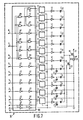
- Fig. 1 shows a circuit diagram of an integrated digital-to-analogue converter comprising a capacitance network
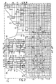
- Fig. 2 shows diagrammatically a part of a plan view of the integrated digital-to-analogue converter with the circuit diagram of Fig. 1 and
- Figures 3 to 5 show diagrammatically associated cross-sections taken on the lines III - III, IV - IV and V - V, respectively, of Fig. 2,
- Fig. 6 shows diagrammatically in plan view the capacitance network of the integrated circuit shown in Figures 1 to 5,
- Fig. 7 shows a circuit diagram of a variation of the integrated digital-to-analogue converter shown in Fig. 1.
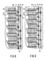
- Fig. 8 shows diagrammatically in plan view a part of another embodiment of the integrated circuit according to the invention, i . e . the part representing the capacitance network and
- Fig. 9 shows diagrammatically in plan view a part of a capacitance network of a still further embodiment of the integrated circuit according to the invention.
- the first embodiment is an integrated circuit 10 comprising a digital-to-analogue converter.
- Fig. 1 shows a circuit diagram with inputs 1 to 8, to which digital information encoded in eight bits can be supplied. Via a number of D flipflops 11 and inverter circuits 12, these digital input signals drive a capacitance network which is constituted by the capacitances C1 to C128. Via the line 13, the D flipflops 11 can be controlled by a suitable clock signal, while via the line 14 a non-synchronous reset signal can be supplied.
- the capacitance network comprises a series of eight capacitances, of which the capacitance value each time increases by a factor 2 in the order of succession of the series.
- the capacitance value of the capacitance C2 is therefore twice that of the capacitance C1.
- the capacitance value of the capacitance C128 is twice that of the capacitance C64 and is 128 times that of the capacitance C1.
- the sides of the capacitances C1 to C128 remote from the inverter circuits 12 are connected via the line 15 to each other and to the signal input of a transistor 16 connected as an emitter follower,
- the transistor is an n -channel field effect transistor of the enhancement type, whose drain electrode is connected to a first supply connection 17 and whose source electrode is connected via a current source 18 serving as a load and constituted, for example, by a suitable resistor to a second supply connection 19.
- This supply connection 19 may be connected, for example, to a point having a suitable reference potential, such as ground.
- the analogue output signal can be derived at 20.
- a transistor 21 may be provided, with which, if desired, a direct voltage component may be added to the input signal of the transistor 16.
- the connection 22 may be connected to a suitable reference voltage source.
- a parasitic capacitance C P is present at the input of the transistor 16. The size of this capacitance C P is determined for a considerable part by the construction of the capacitance network. The capacitance C P otherwise does not influence the accuracy of the digital-to-analogue converter. However, the capacitor C P gives rise to an attenuation of the analogue output signal.
- the inverter circuits 12 especially serve as a buffer between the outputs of the flipflops 11 and the capacitances C1 to C128, as a result of which the connected outputs of the flipflops 11 can be prevented from being too heavily loaded.
- the outputs of the inverter circuits 12 and/or the outputs of the flipflops 11 can be adapted to the size of the capacitance C1 or C2 to C128 connected to the relevant output so that these capacitances can be charged or discharged sufficiently rapidly.
- Fig. 1 shows by way of example that the input 8 is connected via two flipflops 11 and two inverter circuits 12 to the comparatively large capacitance C128. If no buffers are required, the inverter circuits 12 of Fig. 1 may be omitted.
- the outputs of the inverter circuits 12 can assume, depending upon the digital information supplied to the inputs 1 to 8, a voltage which is either equal to a first reference or supply voltage or is equal to a second reference or supply voltage.
- the first reference voltage is, for example, about +10 V and the second reference voltage is, for example, about O V.
- each of the capacitances C1 to C128 will contribute to the signal voltage at the line 15 which is directly proportional to the capacitance value of the relevant capacitance C1 or C2 to C128 and to the output voltage of the relevant inverter circuit 12 and which is inversely proportional to the sum of the capacitance values of the capacitances C P and C1 to C128.
- the output signal at the output 20 can consequently assume between a given minimum and a given maximum value, divided into 255 voltage steps, a voltage whose value is determined by the digital information supplied to the inputs 1 to 8.
- capacitive digital-to-analogue converters have many advantages. They can be used inter alia in audio and video applications and in measuring instruments.
- a disadvantage of these digital-to-analogue converters is that the required number of basic or standard capacitances increases exponentially with the number of bits of the digital signal to be converted.
- the surface area of the common semiconductor body required for the capacitance network often becomes inadmissibly large and/or the ratios between the different capacitance values become too inaccurate so that the analogue output signal does not provide a reliable reflection of the digital information supplied to the input.
- the integrated circuit 10 has several capacitances C1 to C128 which have different capacitance values and it comprises a semiconductor body 30 ( Figures 2 to 5), at a surface of which rows of first capacitance electrodes 31 are arranged side by side, each of these first capacitance electrodes 31 being separated by a dielectric layer 33 from a second capacitance electrode 32.
- the first and second capacitance electrodes 31 and 32 constitute the electrodes of basic capacitances 31, 33, 32 arranged in rows, whilst for forming the capacitances C1 to C128 having different capacitance values different numbers of basic capacitances 31, 33, 32 are connected parallel to each other between one or more first and one or more associated second connection electrodes by interconnecting first capacitance electrodes 31 and second capacitance electrodes 32.
- each row of basic capacitances in the present embodiment comprises twenty basic capacitances 31, 33, 32.
- the plan view of Fig. 2 does not show all rows and moreover the indicated rows are not shown completely.
- first connection electrode 34 is in the form of a conductor track 31, 31a, which comprises the first capacitance electrodes 31 of the relevant row.
- a first group of interconnected second capacitance electrodes 32 of the described rows of n basic capacitances 31, 33, 32 constitutes a second connection electrode 35 associated with the said first connection electrode 34.
- This second connection electrode 35 in the embodiment comprises a number of conductor tracks 32, 32a, which each comprise all or at least a number of second capacitance electrodes 32 of a column of second capacitance electrodes 32.
- These conductor tracks 32, 32a extending in the column direction are interconnected by means of a further conductor track 36 which extends in the row direction and is also associated with the second connection electrode 35.
- a second group of interconnected second capacitance electrodes 32 of these rows of n basic capacitances 31, 33, 32 constitutes a third connection electrode 37.
- This third connection electrode 37 in the embodiment also comprises a number of conductor tracks 32, 32a which extend in the column direction and each comprise all or at least a number of second capacitance electrodes 32 of a column of second capacitance electrodes 32. These conductor tracks 32, 32a are interconnected by means of a further conductor track 38.
- the number of second capacitance electrodes 32 belonging to an associated second connection electrode 35 is smaller than in a second of these rows of n basic capacitances 31, 33, 32.
- all capacitances C1 to C128 have a common second connection electrode 35.
- each of the rows of basic capacitances comprises twenty basic capacitances 31, 33, 32.
- the row indicated in Fig. 2 as the third row from below only one of these basic capacitances 31, 33, 32 is connected to the common connection electrode 35.
- the nineteen remaining base capacitances 31, 33, 32 of this row are connected to the third connection electrode 37.
- too basic capacitances 31, 33, 32 are connected to the second connection electrode 35. Of these two basic capacitances, only one is shown in Fig. 2.
- the complete capacitance matrix of the present embodiment consists of a lower submatrix comprising fourteen rows and an upper submatrix comprising nineteen rows, while the conductor track 36 belonging to the second connection electrode 35 extends in the row direction between these two submatrices. Both submatrices each comprise twenty columns.
- the lower submatrix comprises the capacitances C1, C2, C4 and C8 of Fig. 1.
- the upper submatrix comprises the capacitances C16, C32, C64 and C128 of Fig. 1.
- the connection electrode 34 of one raw in connected to a conductor track 39 the connection electrodes 34 or two rows are connected to a conductor track 40, the connection electrodes of four rows are connected to a conductor track 41 and the connection electrodes of eight rows are connected to a conductor track 42.
- the semiconductor body 30 is a silicon body which mainly consists of n -type material.
- a number of p -type semiconductor regions 50 are formed ( Figures 4 and 5).
- the semiconductor body 30 is covered with a thick insulating layer 51 provided with recesses limiting in usual manner the active regions of the integrated circuit. Below this insulating layer 51, more highly doped channel-interrupting zones (channel stoppers) may be present at the semiconductor surface. In this case these zones are the n -type surface zones 52 and the p- type surface zones belonging to the p -type semiconductor regions 50.
- n - and p -channel transistors are formed.
- the n -channel transistors have an n -type source zone 54 and an n- type drain zone 55 and the p -channel transistors have a p -type source zone 56 and a p -type drain zone 57.
- the n - and p -channel transistors have an insulated gate electrode constituted by a conductor track 58. These conductor tracks 58 also form the electrical signal inputs of the inverter circuits.
- the n -type source zones 54 and the p -type source zones 56 are connected via a conductor track 59 and 60, respectively, to a supply connection for the most negative supply voltage and to a supply connection for the most positive supply voltage, respectively.
- the conductor tracks 59 are also connected by means of a more highly doped p -type surface zone 63 to the p -type semiconductor regions 50.
- the conductor tracks 60 are connected by means of a more highly doped n -type surface zone 64 to the n -type part of the semiconductor body 30.
- the electrical signal outputs of the inverter circuits are constituted by conductor tracks 61, which each connect a p -type drain zone 57 and an n -type drain zone 55 to each other and to one or more first connection electrodes 34 of a row of base capacitances.
- the different semiconductor zones and conductor tracks, where required, are separated from each other by intermediate insulating layers. These insulating layers are provided with openings 62 in which different conductor tracks are electrically connected to each other or to semiconductor zones. Such openings 62 are indicated by broken lines in Fig. 2.
- the capacitance network according to the first embodiment is shown once more diagrammatically in plan view.
- the capacitance network has a matrix of crossings which are arranged in rows and columns and constitute the basic capacitances.
- the conductor tracks 31, 31a and 32, 32a of Fig. 2 also extend in the row direction and in the column direction, respectively.
- the said conductor tracks extending in the row direction can be distinguished in conductor tracks 70 belonging to a first connection electrode of one of the capacitances C1 to C128 and conductor tracks 71 belonging to a first connection electrode of dummy capacitances.
- the conductor tracks extending in the column direction can be distinguished in conductor tracks 72 which are interrupted and consist of at least two parts 72a and 72b and conductor tracks 73 which are not interrupted and comprise second capacitance electrodes of dummy capacitances. Adjacent conductor tracks 73 can be interconnected at their ends.
- the black dots represent electrical connections between conductors arranged in different layers. At the corresponding areas shown in Fig. 2, openings 62 are indicated in Fig. 2.
- the matrix comprises a comparatively large number of dummy capacitances.
- This large number of dummy capacitances is firstly due to the fact that for each of the smaller capacitances C1 to C8 of the capacitance network each time a whole row of basic capacitances is used.
- These smaller capacitances C1 to C8 are located in the submatrix indicated below the conductor track 36 belonging to the second connection electrode.
- the four relevant conductor tracks 70 each comprise a row of twenty crossings, each time two crossings belonging to dummy capacitances both at the beginning and at the end of the row, These four dummy capacitances per row, which are also present in each row of the submatrix indicated above the conductor track 36, are not shown in the circuit diagram of Fig. 1. Of the remaining sixteen crossings per row, one, two, four and eight, respectively, belong to the capacitances C1 to C8, while the remaining fifteen, fourteen, twelve and eight crossings, respectively, belong to dummy capacitances, which are denoted in Fig. 1 by C' 15, C'14, C' 12 and C'8, respectively.
- This division of the crossings into crossings belonging to dummy capacitances and crossings not belonging to dummy capacitances is attained in the present embodiment in that the sixteen conductor tracks 72 in the lower submatrix are interrupted at suitable areas so that these conductor tracks each have two parts 72a and 72b.
- the parts 72a form with the conductor tracks 70 the crossings belonging to the capacitances C1 to C128 and the parts 72b form with the conductor tracks 70 the crossings belonging to the dummy capacitances C'15 to C'8.
- each of the second capacitance electrodes 32 of the first row of n basic capacitances belonging to an associated second connection electrode 35 is located between two adjacent second capacitance electrode 32 of this first row belonging to a further connection electrode 37.
- this further connection electrode is each time the third connection electrode 37 to which also belongs the conductor track 38.
- the integrated circuit may also be provided with one or more further connection electrodes separated from each other and/or from the third connection electrode.
- each conductor track 72a is located at the area or the row of conductor tracks 70 between a conductor track 73 and a conductor track 72b or between two conductor tracks 72b.
- the second capacitance electrodes 32 belonging to the associated second connection electrode 35 of these capacitances C1 to C8 are regularly distributed over the relevant row so that also the interruptions in the conductor tracks 72 are distributed according to a regular pattern over the (sub)matrix.
- the interruptions are arranged so that of each conductor track 72 the part 72a extends at one side of the submatrix at least as far as the edge of the submatrix and the part 72b extends at a side of the submatrix located opposite to this side at least as far as the edge of the submatrix so that each time both the part 72a and the part 72b are accessible at an edge of the submatrix for electrical connection. This means that in each of the conductor tracks 72 at most one interruption is present within the submatrix.
- each row of basic capacitances comprising one or more basic capacitances belonging to one or more of the said capacitances of different capacitance values (each of the first and second rows) is arranged between two row conductors 71, which are connected to a further connection electrode and preferably to the third connection electrode 37.
- each of these adjacent row conductors 71 comprises the first capacitance electrodes 31 of a row of n dummy capacitances.
- n vasic capacitances comprising one or more basic capacitances belonging to one or more of the said capacitances of different capacitance values (each of the first and second rows), i.e. between two adjacent row conductors 70 of the lower submatrix, at least two row conductors 71 so that the interruptions of the column conductors 72 can be located between these two row conductors 71 or need at least not be situated between a row conductor 70 and an adjacent row conductor 71.
- These two adjacent row conductors 71 can be interconnected at their ends, as is indicated in Figures 2 and 6.
- two adjacent tow conductors 71 can be replaced by a single row conductor having a larger width such that the interruptions in the column conductors 72 can be realized within the width dimension of such a widened row conductor.
- the facing ends of the parts 72a and 72b consequently both extends as far as below or above this widened row conductor.
- the lower submatrix has a central part comprising all basic capacitances of this submatrix, of which the first capacitance electrode 31 belongs to a first connection electrode 34 and of which further the second capacitance electrode 32 belongs to a second connection electrode 35.
- the central part of the submatrix is substantially entirely surrounded by an outer part of the submatrix, which comprises two substantially complete rows of basic capacitances located at a first side of the central part and two substantially complete rows of basic capacitances located at a side of the central part opposite to the first side.
- the two rows with row conductors 71 located at the upper side and the two rows with row conductors 71 located at the lower side of the submatrix are concerned.
- the outer part comprises two substantially complete columns of basic capacitances located at a second side of the central part and at least two substantially complete columns of basic capacitances located at a side of the central part opposite to the second side.
- the two columns with column conductors 73 located at the lefthand side of the submatrix and the two columns with column conductors 73 located at the opposite righthand side of the submatrix are concerned here.
- the basic capacitances belonging to the outer part of the submatrix at least either the first capacitance electrode 31 or the second capacitance electrode 32 is connected to a further connection electrode 37.
- the outer part of the submatrix comprises an edge part having a width of two capacitances and conssituted by dummy capacitances.
- the upper submatrix has both at its upper side and at its lower side two row conductors 71. Both at the lefthand and at the righthand side of this submatrix there are arranged two column conductors 73.
- the upper submatrix also has an edge part having a width of two capacitances and constituted by dummy capacitances.
- the matrix as a whole also has an outer part which surrounds substantially completely the central part of the matrix as an edge part having a width of two basic capacitances.
- the (sub)matrix (matrices) has (have) at the lower and upper side three row conductors 71 so that at least at this side the edge part is in the form of an edge part having a width of three dummy capacitances.
- an unfavourable influence of the boundary of the matrix will become manifest especially in one capacitance and perhaps also in a second capacitance of the network farther remote from the edge, while the boundary extending parallel to the column direction will have a comparable influence on substantially all the capacitances of the network.
- the whole edge may also be in the form of a surrounding edge part having a width of three dummy capacitances.
- the basic capacitances of which the first capacitance electrode belongs to a first connection electrode and the second capacitance electrode belongs to a second connection electrode, are then located even farther from the outer edge of the relevant matrix than in the case of an edge having a width of two dummy capacitances. In this manner, the influence of edge effects, which may occur in some of the operations used in the manufacture and which may lead to deviations in the capacitance values of basic capacitances located near the edge of the matrix, is further reduced.
- the parts 72a of the column conductors 72 extend at least as far as practically the upper edge of the upper row conductor 71.
- the upper submatrix may also be closed at the upper side in a similar manner as the lower submatrix at its lower side.
- each of the column conductors 72 at this side has a third part, these third parts at this upper side being interconnected in the same manner as the parts 72b at the lower side of the lower submatrix and being united via a connection part which extends in the row direction and is practically in the same position as the part of the third connection electrode 37 shown at the upper side of Fig. 6.
- All column conductors 72 in this variation have a second interruption, these second interruptions all being situated essentially between the two row conductors 71 shown at the upper side of Fig. 6.
- the object of all the measures described so far is to provide a capacitance matrix constructed as regularly as possible.
- Each of these measures contributes to this objects More particularly the basic capacitances belonging to the smaller capacitances C1 to C8 are surrounded as far as possible completely by substantially identical basic capacitances constituting dummy capacitances. From an electrical point of view, the dummy capacitances of the matrix can be subdivided into three kinds. Dummy capacitances. Dummy capacitances of the first kind have a first capacitance electrode 31, which belongs to a first connection electrode 34 of one of the capacitances C1 to C128.
- the second capacitance electrodes 32 of these dummy capacitances of the first kind belong to the third connection electrode 37 or at least to a further connection electrode.
- the dummy capacitances of this first kind are constituted in the embodiment by crossings of the conductor tracks 70 with the conductor tracks 73 and with the conductor tracks 72b.
- the basic capacitances forming part of the capacitances C'8 to C'15 of Fig. 1 belong to the dummy capacitances of the first kind.
- the dummy capacitances of the second kind have a second capacitance electrode 32 which belongs to a second connection electrode 35.
- the first capacitance electrodes 31 of these dummy capacitances of the second kind are connected to the third connection electrode 37 or at least to a further connection electrode.
- the dummy capacitances of this kind are constituted in the embodiment by the crossings of the conductor tracks 71 with the conductor tracks 72a. In the present embodiment, they provide for a contribution to the capacitance C P of Fig. 1.
- the dummy capacitances of the third kind are constituted by the basic capacitances, of which both the first capacitance electrode 31 and the second capacitance electrode 32 belong to the third connection electrode 37 or at least to a further connection electrodes In the embodiment, these capacitances are the crossings of the conductor tracks 71 with the conductor tracks 73 and with the conductor tracks 72b.
- the capacitance matrix of Fig. 6 comprises 660 basic capacitances in all.
- the lower submatrix has 280 basic capacitances. Of these 280 basic capacitances 265 are dummy capacitances.
- the upper submatrix has 380 base capacitances. The number of dummy capacitances of the upper submatrix is 140. In spite of this extremely large number of dummy capacitances, the overall capacitance value of the capacitance matrix of the first embodiment in a practical example was less than 5.2 pF. The sum of the capacitance values of the capacitances C1 to C128 is only about 2 pF.
- the capacitance matrix occupied a surface area of about 0.07 mm2 .
- a capacitance network for a 10-bit analogue-to-digital converter can be obtained.
- the overall capacitance value of this extended capacitance matrix is then about 15 pF.
- a surface area of about 0.2 mm2 is required.
- such an extended capacitance matrix may alternatively be composed, for example, of a submatrix for the capacitances C1 to C16 with 17 rows of 36 crossings and of a submatrix for the capacitances C32 to C512 with 35 rows of 36 crossings.
- the surface area required for the capacitance matrix is about 0.2 mm2 and the overall capacitance value is about 15 pF.
- the required surface area is about a factor 10 smaller than that of the capacitance matrix known from the aforementioned article in Digest of Technical Papers, ISSCC' 84, which does not comprise any dummy capacitances. This is due to the fact that it has been found that by the use of the present invention the basic capacitances can be given an extremely much smaller size and a considerably smaller capacitance value of, for example, about 8.10 ⁇ 3 pF, while nevertheless the required high degree of accuracy of the realized ratios of capacitance values is obtained.
- the integrated circuit shown in Figures 1 to 6 can be manufactured wholly by methods known in the semiconductor technology, such as doping and deposition treatments, oxidation, photolithographic operations and etching techniques.
- the starting material may be an n -type silicon body 30, which may be composed of an n -type substrate on which an n -type epitaxial layer having a resistivity of about 4 ⁇ .cm and a ⁇ 100> orientation is formed.
- a silicon oxide layer of about 50 nm and a silicon nitride layer having a thickness of about 150 nm are applied to the surface of the body 30.
- arsenic may be implanted for the n -type channel stopper 52.
- a photolacquer pattern is then provided, which serves as a mask when providing the doping for the p -type semiconductor regions 50 and the p -type channel stopper 53.
- boron is implanted at about 150 keV at a dose of about 4.1012 ions/cm2 and at 30 to 40 keV at a dose of about 1.5 . 1013 ions/cm2.
- the first implantation is not masked by the part of the silicon nitride pattern not covered by the photolayer, whereas on the contrary the second implantation is masked by this part.
- a treatment at high temperature for example at about 1200° C, is carried out in an oxidizing atmosphere, during which treatment the field oxide 51 is formed.
- a polycrystalline or an amorphous silicon layer having a thickness of about 0.4 / um can be deposited, which is doped, for example, with phosphorus during and/or after the deposition.
- the conductor tracks 32, 32a are obtained from this deposited silicon layer.
- the tracks have a width of, for example, about 5 / um, while their relative distance can also be about 5 / um.
- the silicon nitride pattern and the underlying oxide are removed and a fresh oxide layer is formed by thermal generation.
- the conductor tracks 32, 32a are then coated with an oxide layer having a thickness of, for example, about 130 nm. In the regions intended for the transistors of the circuit, this fresh oxide layer serves as a gate dielectric.
- a phosphorus-doped polycrystalline or amorphous silicon layer having a thickness of about 0.4 / um is formed.
- the conductor tracks 31, 31a and the gate electrode 59 are obtained from this silicon layer.
- the width of the conductor tracks 31, 31a is, for example, about 5 / um.
- the relative distance of the conductor tracks 31, 31a can be about 5 / um.
- the doping for the n -type source and drain zones 54 and 55 and the n -type zone 64 can be provided.
- arsenic is implanted at about 150 keV at a dose of about 2.1015 ions/cm2. This doping can be diffused at a temperature of about 1100° C further into the semiconductor body 30 after the photolacquer mask has been removed.
- boron can now be implanted for the p -type source and drain zones 56 and 57 and the p -type zone 63.
- a suitable dose is about 3.6 . 1014 ions/cm2 and a suitable implantation energy is, for example, about 40 keV.
- an implantation for the adjustment of the threshold voltage of the p -channel transistors can be effected.
- boron can be implanted at a dose of about 3.1011 ions/cm2 at about 3.1011 ions/cm2 at about 180 keV.
- an insulating layer 65 of, for example, silicon oxide having a thickness of, for example, about 0.8 / um can be deposited.
- the top layer of this silicon oxide layer can be doped, for example, with phosphorus.
- a thermal treatment at about 1000° C can be carried out, during which treatment inter alia the implanted boron diffuses further into the semiconductor body.
- the required windows 62 are opened and a conductive layer of aluminium or another suitable is deposited.
- the conductor tracks 36, 38, 39-42 and 59-61 can be obtained from this conductive layer.
- a further insulating layer (not shown) consisting, for example, of silicon oxide and/or silicon nitride may be provided over this pattern of conductor tracks.
- the base capacitances have a surface area of about 25 / um2 and a capacitance value of about 7.5 to 8.10 ⁇ 3 pF.
- the 8-bit digital-to-analogue converter described had a non-linearity of about 0.25 lsb (least significant bit). It appears therefrom that the realized ratios of capacitance values have a high degree of accuracy in spite of the use of basic capacitances having a very small capacitance value. Thus, it is demonstrated that with the arrangement described of the basic capacitances in a capacitance matrix having a comparatively large number of dummy capacitances, capacitance networks having a comparatively small surface area and, comparatively, a surprisingly high degree of accuracy can be obtained.
- the large capacitances C64 and C128 are subdivided into separately driven capacitances, which each have a capacitance value of 32 basic capacitances.
- a number of flipflops 11 and inverter circuits 12 are added to the circuit arrangement.
- the inputs 1 to 8 and the connections 13 and 14 are connected through a logic network 80, which can be composed in a conventional manner of NAND gates 81, NOR gates 82 and inverter circuits 12, to the flipflops 11.
- the logic network 80 is constructed so that with a small variation of the digital information supplied, for example the step from 127 to 128, the charge variation occurring in the capacitance matrix is limited.
- This charge variation at most corresponds to charging (or discharging) of one capacitance C32 and discharging (or charging) of the capacitances C1 to C16.
- the capacitance C128 is charged and the capacitances C1 to C64 are discharged.
- FIG. 7 Another advantage of the circuit arrangement shown in Fig. 7 is that all outputs of inverter circuits 12 or flipflops 11 connected to the capacitance matrix are loaded by the same number of basic capacitances.
- the said inverter circuits 12 or flip-flops 11 need consequently not be adapted to relatively different capacitive loads. They may be equal to each other, as a result of which inter alia the equal rise and fall times desirable in connection with the peaks that may occur in the output signal of the digital-to-analogue converter can, be realized more readily.
- the capacitance matrix need not necessarily form part of a digital-to-analogue converter.
- Other circuit arrangements comprising plural capacitances of different capacitance values, such as analogue-to-digital converters and switched capacitor circuits, may also be integrated with the use of the present invention, With the capacitance matrix, also capacitance ratios quite different from the powers of 2 described can be realized.
- a common input connection electrode and mutually separated output connection electrodes may be present.
- the capacitance matrix may also have plural mutually separated input connection electrodes and plural mutually separated output connection electrodes. In practical cases, it depends upon the circuit that is integrated, which embodiment is chosen. It may then be desirable to adapt the geometric topology of the capacitance matrix to the desired electrical arrangement of capacitances and/or to the required capacitance ratios.
- each first connection electrode 34 has two interconnected conductor tracks 31, 31a, which comprise first capacitance electrodes 31. Furthermore, conductor tracks 32, 32a extending in the column direction (in the drawing in vertical direction) are present, which each comprise one or more second capacitance electrodes 32. For the sake of simplicity, rows of not more than six basic capacitances 31, 33, 32 are shown in the capacitance matrices of Figures 8 and 9. A dummy capacitance is present at both ends of each row. The second capacitance electrodes 32 of these dummy capacitances are connected to a third connection electrode 37. A number of these connection electrodes 37 are connected to each other through a further conductor track 38.
- the remaining second capacitance electrodes 32 are connected for one part to a third connection electrode 37 and for another part to a second connection electrode 35.
- the connection electrodes 35 are connected to each other through a further conductor track 36.
- Figures 8 and 9 there is indicated in the same manner as in Fig. 6, in which layer of conductor tracks the different conductor tracks are provided.
- the conductor tracks 35, 37 and 32, 32a are located in a first lower layer; the conductor tracks 34 and 31, 31a are located in a second layer insulated from the first layer, while the conductor tracks 36 and 38 belong to a third layer insulated from the first layer and the second layer. Furthermore, a few openings 62 in an intermediate insulating layer are indicated.
- Fig. 8 shows five capacitances with capacitances ratios 1 : 2 : 4 : 8 : 8. If in Fig. 8 the conductor track 36 is omitted, the upper part of the capacitance matrix shown comprises two capacitances with a capacitance ratio 1 : 2, which have mutually separated first connection electrodes 34 and a common second connection electrode 35. These two capacitances may constitute a series arrangement. Furthermore, a comparable series arrangement comprising five capacitances having a capacitance value four times that of the smallest capacitance is present in the remaining part.
- Fig. 9 shows four capacitances with capacitance ratios 1 : 2 : 4 : 8. If in Fig. 9 the conductor track 36 is omitted, each of these four capacitances has a separated first connection electrode 34 and a separated second connection electrode 35.
- FIGS 8 and 9 consequently show inter alia that quite different configurations of capacitances can be realized already with comparatively small adaptations in the geometric topology of the capacitance matrix with respect to the circuit arrangement.
- the intergrated circuit may also be constructed in NMOS or PMOS technology. instead of in CMOS technology, Furthermore, the capacitance matrix described may form part of a bipolar integrated circuit, in which the conductor tracks and connection electrodes are provided, for example, in two layers of a suitable conductive material, such as aluminium.
- the conductor tracks 31, 31a and 34 of Fig. 2 may then be provided in the same layer as the conductor tracks 36, 59, 60 and 61, while the conductor tracks 38 to 42 may be provided in the same layer as the conductor tracks 32, 32a.
- the row and column conductors of silicon described may be replaced wholly or in part by or converted into a suitable silicide.
- the row conductors, the column conductors and the capacitance electrodes are made of the same materials or at least of similar materials.
- the said doped zones may be of a conductivity type which is opposite to that of the semiconductor body 30.
- the doping concentration of the doped zones may impose a limitation on the maximum permissible operating voltage of the capacitances and/or on the polarity of this operating voltage.
- the conductor tracks comprising the capacitance electrodes have the same width throughout their length. In connection with the desired compactness of the capacitance matrix, such an embodiment is to be preferred. However, if required, the conductor tracks may have widened parts at the area of the capacitance electrodes 31, 32, for example, in order to increase the capacitance value of the basic capacitances.
- the semiconductor body may also be formed from a monocrystalline semiconductor layer which extends on an insulating substrate.
- the capacitance matrix may be realized on and/or in the semiconductor layer or may be provided directly on the insulating substrate.
- circuit elements of the integrated circuit such as transistors and resistors, may also be realized in known manner wholly or in part in a polycrystalline semiconductor layer that may be recrystallized.
- other materials may be used.
- silicon for example, other semiconductors, such as germanium or A III - B V compounds, may be used.
- Oxide layers obtained by thermal generation may be replaced by deposited oxide layers or, for example, by silicon nitride layers.
- oxide layers and/or nitride layers other suitable insulating layers, such as aluminium oxide layers, may be used.
- insulating layers may consist of several sublayers or different insulating materials or of a mixture of such materials.
- oxynitride layers may be used.
- the dielectric of the basic capacitances may consist wholly or in part of silicon nitride, while the comparatively high dielectric constant of this material may be advantageous.
- the use of the invention leads to integrated circuits comprising capacitances of different capacitance values, in which the ratios of the capacitance values are comparatively accurate and the absolute capacitance valued are comparatively small. Consequently, not only is the area required for the integrated capacitances comparatively small, but generally also the dissipation occurring in the capacitance matrix is comparatively low. This low dissipation is especially advantageous because the maximum permissible dissipation of the integrated circuit as a whole causes the designer of integrated circuits to meet more or less serious limitations inter alia because of the maximum permissible temperature of the semiconductor body.
- the peak currents occurring in the capacitance matrix are comparatively small, as a result of which disturbances are less liable to occur in other parts of the integrated circuits.
- the conductor tracks in the capacitance matrix are comparatively short, as a result of which the series resistance per unit length in these conductor tracks is allowed to be comparatively large without the operating speed being too strongly limited thereby.
Landscapes
- Engineering & Computer Science (AREA)
- Theoretical Computer Science (AREA)
- Semiconductor Integrated Circuits (AREA)
- Design And Manufacture Of Integrated Circuits (AREA)
- Compression, Expansion, Code Conversion, And Decoders (AREA)
Applications Claiming Priority (2)
| Application Number | Priority Date | Filing Date | Title |
|---|---|---|---|
| NL8403932 | 1984-12-24 | ||
| NL8403932A NL8403932A (nl) | 1984-12-24 | 1984-12-24 | Geintegreerde schakeling met kapaciteiten van verschillende kapaciteitswaarden. |
Publications (2)
| Publication Number | Publication Date |
|---|---|
| EP0186239A1 EP0186239A1 (en) | 1986-07-02 |
| EP0186239B1 true EP0186239B1 (en) | 1991-03-20 |
Family
ID=19844966
Family Applications (1)
| Application Number | Title | Priority Date | Filing Date |
|---|---|---|---|
| EP85202045A Expired EP0186239B1 (en) | 1984-12-24 | 1985-12-11 | Integrated circuit comprising capacitances of different capacitance values |
Country Status (7)
| Country | Link |
|---|---|
| US (1) | US4929998A (index.php) |
| EP (1) | EP0186239B1 (index.php) |
| JP (1) | JPS61156851A (index.php) |
| CN (1) | CN1003067B (index.php) |
| CA (1) | CA1241454A (index.php) |
| DE (1) | DE3582231D1 (index.php) |
| NL (1) | NL8403932A (index.php) |
Families Citing this family (10)
| Publication number | Priority date | Publication date | Assignee | Title |
|---|---|---|---|---|
| GB2245419A (en) * | 1990-06-20 | 1992-01-02 | Philips Electronic Associated | Ratioed capacitances in integrated circuits |
| FR2714528B1 (fr) * | 1993-12-27 | 1996-03-15 | Sgs Thomson Microelectronics | Structure de test de circuit intégré. |
| EP0704904B1 (en) * | 1994-09-30 | 1999-05-26 | Yozan Inc. | Capacitance forming method |
| JP3182079B2 (ja) * | 1996-05-30 | 2001-07-03 | 住友金属工業株式会社 | 半導体装置の容量素子の配線構造 |
| WO2001059843A1 (en) * | 2000-02-10 | 2001-08-16 | Conexant Systems, Inc. | An improved capacitor in semiconductor chips |
| EP1182778A1 (en) * | 2000-07-21 | 2002-02-27 | Semiconductor Ideas to The Market (ItoM) BV | Receiver comprising a digitally controlled capacitor bank |
| US6980414B1 (en) | 2004-06-16 | 2005-12-27 | Marvell International, Ltd. | Capacitor structure in a semiconductor device |
| US8169014B2 (en) * | 2006-01-09 | 2012-05-01 | Taiwan Semiconductor Manufacturing Co., Ltd. | Interdigitated capacitive structure for an integrated circuit |
| EP1863090A1 (en) | 2006-06-01 | 2007-12-05 | Semiconductor Energy Laboratory Co., Ltd. | Semiconductor device and method for manufacturing semiconductor device |
| US9177909B2 (en) | 2013-08-14 | 2015-11-03 | United Microelectronics Corp. | Semiconductor capacitor |
Family Cites Families (1)
| Publication number | Priority date | Publication date | Assignee | Title |
|---|---|---|---|---|
| JPS58103163A (ja) * | 1981-12-16 | 1983-06-20 | Hitachi Ltd | 容量素子 |
-
1984
- 1984-12-24 NL NL8403932A patent/NL8403932A/nl not_active Application Discontinuation
-
1985
- 1985-12-11 EP EP85202045A patent/EP0186239B1/en not_active Expired
- 1985-12-11 DE DE8585202045T patent/DE3582231D1/de not_active Expired - Lifetime
- 1985-12-20 CA CA000498366A patent/CA1241454A/en not_active Expired
- 1985-12-21 CN CN85109668A patent/CN1003067B/zh not_active Expired
- 1985-12-24 JP JP60289558A patent/JPS61156851A/ja active Granted
-
1988
- 1988-10-25 US US07/263,992 patent/US4929998A/en not_active Expired - Lifetime
Also Published As
| Publication number | Publication date |
|---|---|
| CN85109668A (zh) | 1986-06-10 |
| CA1241454A (en) | 1988-08-30 |
| EP0186239A1 (en) | 1986-07-02 |
| DE3582231D1 (de) | 1991-04-25 |
| CN1003067B (zh) | 1989-01-11 |
| JPS61156851A (ja) | 1986-07-16 |
| JPH0455342B2 (index.php) | 1992-09-03 |
| NL8403932A (nl) | 1986-07-16 |
| US4929998A (en) | 1990-05-29 |
Similar Documents
| Publication | Publication Date | Title |
|---|---|---|
| US6329260B1 (en) | Analog-to-digital converter and method of fabrication | |
| US5481129A (en) | Analog-to-digital converter | |
| US4890142A (en) | Power MOS transistor structure | |
| US5382916A (en) | Differential voltage follower | |
| US5994741A (en) | Semiconductor device having digital and analog circuits integrated on one chip | |
| US5369309A (en) | Analog-to-digital converter and method of fabrication | |
| US4033797A (en) | Method of manufacturing a complementary metal-insulation-semiconductor circuit | |
| EP0136952B1 (en) | A gate array | |
| US5376816A (en) | Bi-cmos integrated circuit device having buried region use in common for bipolar and mos transistors | |
| EP0186239B1 (en) | Integrated circuit comprising capacitances of different capacitance values | |
| GB2163901A (en) | A semiconductor integrated circuit device and a process for manufacturing such a device | |
| US20020036326A1 (en) | Analog-to-digital converter and method of fabrication | |
| US4326136A (en) | Threshold circuit using complementary field effect transistors | |
| JPH02503255A (ja) | 収束イオンビーム技術により形成されたアナログ・デジタル変換器 | |
| US4161742A (en) | Semiconductor devices with matched resistor portions | |
| US4398207A (en) | MOS Digital-to-analog converter with resistor chain using compensating "dummy" metal contacts | |
| GB1563863A (en) | Igfet inverters and methods of fabrication thereof | |
| SE507892C2 (sv) | Förfarande och anordning för att åstadkomma en konstruktion för digital-till-analogomvandling med hög prestanda | |
| CA1102009A (en) | Integrated circuit layout utilizing separated active circuit and wiring regions | |
| JPS5873236A (ja) | 論理回路 | |
| US4631570A (en) | Integrated circuit having buried oxide isolation and low resistivity substrate for power supply interconnection | |
| JP2814079B2 (ja) | 半導体集積回路とその製造方法 | |
| US4124807A (en) | Bistable semiconductor flip-flop having a high resistance feedback | |
| EP0234269A2 (en) | High voltage semiconductor integrated circuit | |
| DE69228609T2 (de) | Analog/digitalwanlder und herstellungsverfahren |
Legal Events
| Date | Code | Title | Description |
|---|---|---|---|
| PUAI | Public reference made under article 153(3) epc to a published international application that has entered the european phase |
Free format text: ORIGINAL CODE: 0009012 |
|
| AK | Designated contracting states |
Kind code of ref document: A1 Designated state(s): DE FR GB IT NL |
|
| 17P | Request for examination filed |
Effective date: 19861222 |
|
| 17Q | First examination report despatched |
Effective date: 19890126 |
|
| GRAA | (expected) grant |
Free format text: ORIGINAL CODE: 0009210 |
|
| AK | Designated contracting states |
Kind code of ref document: B1 Designated state(s): DE FR GB IT NL |
|
| PG25 | Lapsed in a contracting state [announced via postgrant information from national office to epo] |
Ref country code: NL Effective date: 19910320 |
|
| REF | Corresponds to: |
Ref document number: 3582231 Country of ref document: DE Date of ref document: 19910425 |
|
| ITF | It: translation for a ep patent filed | ||
| ET | Fr: translation filed | ||
| NLV1 | Nl: lapsed or annulled due to failure to fulfill the requirements of art. 29p and 29m of the patents act | ||
| PLBE | No opposition filed within time limit |
Free format text: ORIGINAL CODE: 0009261 |
|
| STAA | Information on the status of an ep patent application or granted ep patent |
Free format text: STATUS: NO OPPOSITION FILED WITHIN TIME LIMIT |
|
| 26N | No opposition filed | ||
| ITPR | It: changes in ownership of a european patent |
Owner name: CAMBIO RAGIONE SOCIALE;PHILIPS ELECTRONICS N.V. |
|
| REG | Reference to a national code |
Ref country code: FR Ref legal event code: CD |
|
| PGFP | Annual fee paid to national office [announced via postgrant information from national office to epo] |
Ref country code: GB Payment date: 19971201 Year of fee payment: 13 |
|
| PGFP | Annual fee paid to national office [announced via postgrant information from national office to epo] |
Ref country code: FR Payment date: 19971223 Year of fee payment: 13 |
|
| PGFP | Annual fee paid to national office [announced via postgrant information from national office to epo] |
Ref country code: DE Payment date: 19980223 Year of fee payment: 13 |
|
| REG | Reference to a national code |
Ref country code: FR Ref legal event code: CD |
|
| PG25 | Lapsed in a contracting state [announced via postgrant information from national office to epo] |
Ref country code: GB Free format text: LAPSE BECAUSE OF NON-PAYMENT OF DUE FEES Effective date: 19981211 |
|
| GBPC | Gb: european patent ceased through non-payment of renewal fee |
Effective date: 19981211 |
|
| PG25 | Lapsed in a contracting state [announced via postgrant information from national office to epo] |
Ref country code: FR Free format text: LAPSE BECAUSE OF NON-PAYMENT OF DUE FEES Effective date: 19990831 |
|
| REG | Reference to a national code |
Ref country code: FR Ref legal event code: ST |
|
| PG25 | Lapsed in a contracting state [announced via postgrant information from national office to epo] |
Ref country code: DE Free format text: LAPSE BECAUSE OF NON-PAYMENT OF DUE FEES Effective date: 19991001 |