EP0185956A1 - Kühlvorrichtung für eine Doppelbandstranggiessmaschine - Google Patents
Kühlvorrichtung für eine Doppelbandstranggiessmaschine Download PDFInfo
- Publication number
- EP0185956A1 EP0185956A1 EP85115089A EP85115089A EP0185956A1 EP 0185956 A1 EP0185956 A1 EP 0185956A1 EP 85115089 A EP85115089 A EP 85115089A EP 85115089 A EP85115089 A EP 85115089A EP 0185956 A1 EP0185956 A1 EP 0185956A1
- Authority
- EP
- European Patent Office
- Prior art keywords
- cooling
- ports
- inlet
- casting machine
- belt
- Prior art date
- Legal status (The legal status is an assumption and is not a legal conclusion. Google has not performed a legal analysis and makes no representation as to the accuracy of the status listed.)
- Granted
Links
Images


Classifications
-
- B—PERFORMING OPERATIONS; TRANSPORTING
- B22—CASTING; POWDER METALLURGY
- B22D—CASTING OF METALS; CASTING OF OTHER SUBSTANCES BY THE SAME PROCESSES OR DEVICES
- B22D11/00—Continuous casting of metals, i.e. casting in indefinite lengths
- B22D11/12—Accessories for subsequent treating or working cast stock in situ
- B22D11/124—Accessories for subsequent treating or working cast stock in situ for cooling
-
- B—PERFORMING OPERATIONS; TRANSPORTING
- B22—CASTING; POWDER METALLURGY
- B22D—CASTING OF METALS; CASTING OF OTHER SUBSTANCES BY THE SAME PROCESSES OR DEVICES
- B22D11/00—Continuous casting of metals, i.e. casting in indefinite lengths
- B22D11/06—Continuous casting of metals, i.e. casting in indefinite lengths into moulds with travelling walls, e.g. with rolls, plates, belts, caterpillars
- B22D11/0637—Accessories therefor
- B22D11/0677—Accessories therefor for guiding, supporting or tensioning the casting belts
Definitions
- the present invention relates to a belt type continuous casting machine and, more particularly, to a cooling apparatus for a steel belt type continuous casting machine which enables an improving of a flatness of a slab.
- a belt mold is proposed, formed by a pair of metal belts and a pair of side fixed board disposed between these belts, with the belt mold being cooled by a flow of cooling water in a gap or water film portion defined by the metal belt and a cooling pad having a plurality of inlet ports and outlet ports, and being disposed at a back portion of the metal belt.
- the cooling water is introduced from a plurality of inlet ports provided on the cooling pad and is discharged from outlet ports disposed around the inlet ports
- the cooling pad includes elongated or oblong grooves around the inlet ports on the surface thereof and the gap or water film portion is formed between the metal belt and cooling pad.
- the gap or water film portion functions as a bearing by supporting the external load which is represented by the static pressure of the molten steel applied to the belt mold, whereby the steel belt and the cooling pad are maintained out of contact so as to minimize if not prevent wear of the belt caused by frictional sliding.
- the cooling strength through the belt is evaluated by a heat transfer rate a w , and a relationship between the flow velocity V W , and a thickness of the water film in accordance with the following relationship:
- the cooling strength ⁇ w is directly proportional to the flow velocity V W and inversely proportional to the water film thickness ⁇ if the supply flow rate is constant.
- the lower limit of the water film thickness 6 is set at 0.5 mm taking into consideration a rise in temperature of the cooling water itself.
- the aim underlying the present invention essential resides in providing a cooling belt apparatus for a belt type continuous casting machine wherein an arrangement is provided for enabling a maintaining of at least one of a cooling effect and supporting effect to an external load substantially equal over an entire surface of the belt mold.
- the deformation of the belt mold is prevented in order to obtain a flat cast slab with a good surface finish.
- a belt type continuous casting machine which includes a belt mold having a pair of movable belts and side members, a cooling pad is disposed adjacent to the movable belt for forming a water film portion therebetween and includes a plurality of ports for supplying or running cooling fluid into the water film portion. At least one of the diameters of the ports and a vertical distance between the ports is varied for equally controlling a fluid pressure in the water film portion.
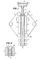
- a belt type continuous casting machine includes a container to tundish 11 accommodating molten steel therein, the container 11 includes a nozzle 12 at a bottom thereof.
- a belt mold 20 includes a pair of metal belts 4 and a pair of fixed side boards 19 disposed between the metal belts 4. The molten steel is supplied or poured from the container 11 through the nozzle 12 into the belt mold 20.
- a cooling pad 3 having a plurality of ports for enabling a running or supplying of a cooling medium, is provided on a back portion of each of the metal belts 4 and defines a gap portion 5 between the metal belt 4 and the cooling pads 3 as shown most clearly in Fig. 2.
- the belt mold 20 is cooled by running a cooling medium such as, for example, cooling water, in the gap portion 5.
- the molten steel 10 develops into a solidified shell 6 by cooling in the metal mold 20.
- a plurality of guide rolls 14a-14c drive the metal belt 4 synchronously with a drawing of the cast slab, and a plurality of driven pinch rolls 13 draw the cast slab from the metal belt mold 20.
- the cooling pad 3 is provided with a plurality of inlet ports 1 and outlet ports 2, with the belt mold 20 being cooled by the flow of cooling water in the gap or water film portion 5 defined between the metal belt 4 and the cooling pad 3.
- the cooling water is introduced from a plurality of the inlet ports provided in the cooling pad and is discharged from a plurality of the outlet ports 2 disposed around the inlet ports 1.
- a plurality of drain portions 9 are provided for discharging the cooling water flowing through the outlet ports 2 and a plurality of water supply portions 18 are provided for introducing the cooling water into the water film or gap portion 5 through the inlet ports 1.
- a cooling pad 3a may be provided which differs from the cooling pad 3 by virtue of the provision of an inlet port 1 and an outlet port 2 having an oblong (a x b) groove 8 disposed therearound.
- the cooling pad 3a forms a steady or stable gap or water film portion 5 between the respective metal belts 4 and the cooling pad 3a.
- the gap or water film portion 5 has a cooling function for restricting any rise of temperature caused by heat from the molten metal steel 10 within the belt mold 20.
- the water film or gap portion 5 functions as a bearing for supporting the external load which is represented by the static pressure of the molten steel 10 in the metal mold 20 to prevent contact between the metal belt 4 and the cooling pad 3 in order to prevent the wear and tear of the metal belt caused by friction or sliding.
- the cooling apparatus for the belt type casting machine of the present invention has a number of significant features.
- the inlet ports 1 are made smaller at the upper portion of the cooling pad 3 or 3a where a low pressure is required and are made larger at the lower portion of the cooling pad 3 or 3a where a high pressure is required, whereby the pressure of each portion of the cooling pad 3 or 3 a is balanced by controlling the pressure on the basis of the difference in the pressure loss in the inlet ports 1, while in contrast the diameters of the outlet portions 2 are made larger at the upper portion and smaller at the lower portion so that the thickness of the water film can be secured.
- the vertical distance between the inlet port and adjacent outlet ports 2 is greater at the upper portion and smaller at the lower portion of the cooling pad 3 or 3a whereby the difference in required pressure in the vertical direction is based on the difference in pressure loss caused by the difference in length of each flow path.
- the inadequate cooling ability found in the cooling pad 3 or 3a for the belt mold may be solved by considerably raising the flow rate. In other words, by providing a sufficient flow rate to adequately cool a portion where cooling strength is poor or by forming the surface of the cooling pad to be flat.
- an unsolved problem which still remains in that the distribution of pressure applied to the belt mold is such that there is a direct deflective deformation of the metal belt.
- the amount of deflection S b of a metal belt is obtained by the following relationship: where:
- a material with a high rigidity, namely with a high or great value of EI, which is used for the metal belt is advantageous with respect to deflection but disadvantageous in various points with regard to related equipment as a whole.
- rigidity increases when the metal belt thickness is increased, but ultimately it is disadvantageously necessary to make the entire size of equipment larger taking into consideration the fatigue strength of the belt which is bent and straightened by guide rolls.
- the load P and the distance l between the inlet port and the outlet port will now further be described.
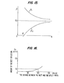
- the external load P applied to the belt mold is a pressure represented by a static pressure p of a molten steel which increases as the belt mold travels downward in a vertical direction, and is qualitatively represented by the line a in Fig. 7.
- the load P is supported by the pressure of the running water between the inlet port 1 and outlet port 2 in the water film or gap portion 5 provided between the metal belt 4 and the cooling pad 3 or 3a.
- the supporting pressure Pb is represented by the line b which forms a peak portion at the inlet port portion b l while a trough portion is formed at the outlet port portion b 2 in comparison with the line a' which is symmetrical with the line a.
- the pressure is balanced between the inlet port 1 and the outlet port 2 as a result of the following relationship: where:
- the belt 4 Since it is impossible to equalize the supporting pressure p b with the external load pressure p along the vertical direction of the belt mold, the belt 4 receives the combined pressures p b and p represented in Fig. 7 as a load, as is shown in Fig. 8, and the dispersion of the distribution the load causes deflection.
- the distribution of the supporting pressure p b is determined by the influence of the running water on dynamic/static pressure and various pressure losses, and it is difficult to grasp accurately the form of the distribution.
- the metal belt 4 will be deflected as shown in Fig. 9.
- the approximate amount of deflection 6 b is qualitatively represented in Fig.
- the diameters of the inlet ports 1 and outlet ports 2 are varied in accordance with an external load, and the vertical distance between each inlet port 1 and the outlet port 2 adjacent thereto is also varied with respect to each of the corresponding distances between the other inlet ports 1 and adjacent outlet ports 2.
- Fig. 11 illustrates a relationship between ⁇ P and 6 in the case of Q being given.
- the composite graph of the distribution of the external load applied to the belt mold between the inlet and outlet ports 1, 2 and the support pressure distribution may be depicted at the line K in Fig. 12. From valid conditions for formula (2) and the continuity of the pressure applied in the vertical direction, the average supporting pressure P k at the inlet port 1 and that of P H at the outlet port 2 can be determined uniformly with respect to the static pressure of molten steel as a pressure necessary for the attached support.
- the pressures P K , P H are determined on the basis of the pressure drop occurring when the water flows into the inlet port 1 or flows to the water film of gap portion 5.
- Formula (8) is changed into the following formula (9) by substituting formulas (8a) and (8b) for Q and lB:
- the diameters of the ports 1, 2 are determined.
- the diameters and the pressures of the upper and lower inlet ports are ⁇ d a , ⁇ d d , p Ka and P Kd , respectively.
- the diameter of the lower inlet ⁇ d d2 is approximately ⁇ d a2 + 3 mm.
- selection of diameters of the outlet ports ⁇ d h is opposite to those of the inlet ports, namely, large at the upper portion and small at the lower portion in accordance with the line C H in Fig. 13 in order to make the ⁇ P at the upper portion small and the ⁇ P at the lower portion large.
- the external load applied to the belt mold includes a uniform pressure by virtue of the belt tension which is applied to the mold portion having a curvature, and the diameters of the inlet and outlet ports are selected in correspondence with the external load including this uniform pressure. It is unnecessary to vary the diameters of these ports at a lower portion of the mold where the slab is adequately formed and the surface quality of the cast slab is not affected by the degree of pressure.
- K' ⁇ s
- V w 4.5 m/s
- K 37 x 10 -6 Kg/mm2
- ⁇ 1 and ⁇ 2 are about 0.55 and 0.45, respectively.
- the upper pressure ⁇ P u is higher than the lower pressure ⁇ P d .
- the present invention determines the dimensions of ⁇ da' ⁇ dd' ⁇ dh' l u' and l d of the cooling pad shown in Fig. 4 on the basis of the above described theory.
- Figure 17 shows the relationship between, on the one hand, the amount of belt deflection ⁇ b , and, on the other hand, the flow rate Q necessary for cooling and the length of the flow path 1.
- the solid curve extending from the left upper portion to the right lower portion represents the minimum flow rate Q required for cooling, and the solid curves extending from the right lower portion to the left upper portion represent the amount of belt deflection ⁇ b with respect to each length l of the flow path.
- the diameters of the inlet and outlet ports 1, 2 are varied in correspondence with an external load, or the vertical distance from each inlet port to the adjacent outlet port 2 is varied with respect to other inlet and outlet ports 1, 2.
- the cooling apparatus for the belt type continuous casting machine ensures forming of equal water film thickness between the cooling pad and the movable metal belt in order to enable uniform cooling of the belt mold, and obtaining of flat cast slab with good surface.
Landscapes
- Engineering & Computer Science (AREA)
- Mechanical Engineering (AREA)
- Continuous Casting (AREA)
Applications Claiming Priority (2)
| Application Number | Priority Date | Filing Date | Title |
|---|---|---|---|
| JP59251380A JPS61129259A (ja) | 1984-11-28 | 1984-11-28 | ベルト式連鋳機の冷却方法および装置 |
| JP251380/84 | 1984-11-28 |
Publications (2)
| Publication Number | Publication Date |
|---|---|
| EP0185956A1 true EP0185956A1 (de) | 1986-07-02 |
| EP0185956B1 EP0185956B1 (de) | 1990-02-07 |
Family
ID=17221969
Family Applications (1)
| Application Number | Title | Priority Date | Filing Date |
|---|---|---|---|
| EP85115089A Expired - Lifetime EP0185956B1 (de) | 1984-11-28 | 1985-11-28 | Kühlvorrichtung für eine Doppelbandstranggiessmaschine |
Country Status (5)
| Country | Link |
|---|---|
| US (1) | US4679611A (de) |
| EP (1) | EP0185956B1 (de) |
| JP (1) | JPS61129259A (de) |
| KR (1) | KR900003060B1 (de) |
| DE (1) | DE3575880D1 (de) |
Cited By (3)
| Publication number | Priority date | Publication date | Assignee | Title |
|---|---|---|---|---|
| EP0222494A1 (de) * | 1985-10-03 | 1987-05-20 | Kawasaki Steel Corporation | Bandstranggiessanlage und Verfahren zur Schmelzenauslaufverhütung in einer solchen Giessanlage |
| EP0605094A1 (de) * | 1992-12-31 | 1994-07-06 | KAISER ALUMINUM & CHEMICAL CORPORATION | Unabhängiges Abschredsystem zur kontrollierten Kühlung eines kontinuierlichen Bandes |
| WO1997025170A1 (en) * | 1996-01-11 | 1997-07-17 | Larex Ag | Cooling system for a belt caster and associated methods |
Families Citing this family (7)
| Publication number | Priority date | Publication date | Assignee | Title |
|---|---|---|---|---|
| JPS63123551A (ja) * | 1986-11-12 | 1988-05-27 | Kawasaki Steel Corp | ベルト式連続鋳造機のベルト冷却方法 |
| JPS63144847A (ja) * | 1986-12-10 | 1988-06-17 | Kawasaki Steel Corp | ベルト式連続鋳造機のベルト冷却装置 |
| BE1001428A6 (fr) * | 1988-02-03 | 1989-10-31 | Centre Rech Metallurgique | Dispositif de refroidissement d'un metal pendant la coulee. |
| US5725046A (en) * | 1994-09-20 | 1998-03-10 | Aluminum Company Of America | Vertical bar caster |
| US6755236B1 (en) * | 2000-08-07 | 2004-06-29 | Alcan International Limited | Belt-cooling and guiding means for continuous belt casting of metal strip |
| US11000893B2 (en) | 2017-04-11 | 2021-05-11 | Hazelett Strip-Casting Corporation | System and method for continuous casting |
| CN109226736B (zh) * | 2018-10-29 | 2023-04-25 | 甘肃酒钢集团宏兴钢铁股份有限公司 | 一种减少人为测量误差的检查板坯水口尺寸的方法 |
Citations (4)
| Publication number | Priority date | Publication date | Assignee | Title |
|---|---|---|---|---|
| FR2347999A1 (fr) * | 1976-04-13 | 1977-11-10 | Escher Wyss Sa | Dispositif de guidage de la billette dans une machine de coulee continue |
| FR2382297A1 (fr) * | 1977-03-04 | 1978-09-29 | Larex Ag | Procede de refroidissement et de guidage d'une bande de coulee a mouvement circulaire dans un dispositif de coulee continue a plaques metalliques |
| US4190103A (en) * | 1975-04-15 | 1980-02-26 | Alcan Research And Development Limited | Continuous casting of metal strip between moving belts |
| EP0008901A1 (de) * | 1978-09-01 | 1980-03-19 | Alcan Research And Development Limited | Bandgiessmaschine |
Family Cites Families (1)
| Publication number | Priority date | Publication date | Assignee | Title |
|---|---|---|---|---|
| JPS6054247A (ja) * | 1983-09-05 | 1985-03-28 | Mitsubishi Heavy Ind Ltd | 双ベルト式連続鋳造方法 |
-
1984
- 1984-11-28 JP JP59251380A patent/JPS61129259A/ja active Granted
-
1985
- 1985-11-28 EP EP85115089A patent/EP0185956B1/de not_active Expired - Lifetime
- 1985-11-28 KR KR1019850008912A patent/KR900003060B1/ko not_active IP Right Cessation
- 1985-11-28 DE DE8585115089T patent/DE3575880D1/de not_active Expired - Lifetime
- 1985-11-29 US US06/802,722 patent/US4679611A/en not_active Expired - Lifetime
Patent Citations (4)
| Publication number | Priority date | Publication date | Assignee | Title |
|---|---|---|---|---|
| US4190103A (en) * | 1975-04-15 | 1980-02-26 | Alcan Research And Development Limited | Continuous casting of metal strip between moving belts |
| FR2347999A1 (fr) * | 1976-04-13 | 1977-11-10 | Escher Wyss Sa | Dispositif de guidage de la billette dans une machine de coulee continue |
| FR2382297A1 (fr) * | 1977-03-04 | 1978-09-29 | Larex Ag | Procede de refroidissement et de guidage d'une bande de coulee a mouvement circulaire dans un dispositif de coulee continue a plaques metalliques |
| EP0008901A1 (de) * | 1978-09-01 | 1980-03-19 | Alcan Research And Development Limited | Bandgiessmaschine |
Cited By (5)
| Publication number | Priority date | Publication date | Assignee | Title |
|---|---|---|---|---|
| EP0222494A1 (de) * | 1985-10-03 | 1987-05-20 | Kawasaki Steel Corporation | Bandstranggiessanlage und Verfahren zur Schmelzenauslaufverhütung in einer solchen Giessanlage |
| US4759400A (en) * | 1985-10-03 | 1988-07-26 | Kawasaki Steel Corporation | Belt type cast sheet continuous caster and prevention of melt leakage in such a caster |
| EP0605094A1 (de) * | 1992-12-31 | 1994-07-06 | KAISER ALUMINUM & CHEMICAL CORPORATION | Unabhängiges Abschredsystem zur kontrollierten Kühlung eines kontinuierlichen Bandes |
| AU663421B2 (en) * | 1992-12-31 | 1995-10-05 | Alcoa Inc. | Contained quench system for controlled cooling of continuous web |
| WO1997025170A1 (en) * | 1996-01-11 | 1997-07-17 | Larex Ag | Cooling system for a belt caster and associated methods |
Also Published As
| Publication number | Publication date |
|---|---|
| US4679611A (en) | 1987-07-14 |
| JPS61129259A (ja) | 1986-06-17 |
| KR900003060B1 (ko) | 1990-05-07 |
| KR860003865A (ko) | 1986-06-13 |
| EP0185956B1 (de) | 1990-02-07 |
| JPH0445256B2 (de) | 1992-07-24 |
| DE3575880D1 (de) | 1990-03-15 |
Similar Documents
| Publication | Publication Date | Title |
|---|---|---|
| CN100409975C (zh) | 用于确定连铸坯中凝固末端的位置的方法和装置 | |
| US3926244A (en) | Method of controlling the cooling rate of narrow side walls of plate molds as a function of the casting taper during continuous casting | |
| EP0185956A1 (de) | Kühlvorrichtung für eine Doppelbandstranggiessmaschine | |
| US3915216A (en) | Method of controlling the secondary cooling of a continuously cast strand | |
| EP0686445B1 (de) | Verfahren zum Kontrollieren der Verformung von Seitenwänden einer Kokille sowie Stranggiesskokille | |
| CN1318164C (zh) | 在连续浇铸结晶器中、尤其在铸造液面处的热传导的匹配 | |
| US4759400A (en) | Belt type cast sheet continuous caster and prevention of melt leakage in such a caster | |
| CA1191321A (en) | Method and apparatus for continuous casting of metal under controlled load conditions | |
| US4167964A (en) | Continuous casting plant | |
| US5205982A (en) | Tundish flow control | |
| EP0755737B1 (de) | Stranggiessverfahren für rostfreien austenitischen stahl | |
| US6152209A (en) | Method and device for measuring and regulating the temperature and quantity of cooling water for water-coolable walls of a continuous casting mold | |
| CA2026724C (en) | Method and apparatus for improved melt flow during continuous strip casting | |
| GB2266256A (en) | Delivery nozzle in metal strip casting | |
| US6044896A (en) | Method and apparatus for controlling the gap in a strip caster | |
| AU6985398A (en) | Radial-flow distributor for wide uniform nonturbulent non-dribbling pouring of molten metal into a continuous metal-casting machine - methods and apparatus | |
| US4635703A (en) | Cooling pad for use in a continuous casting apparatus for the production of cast sheets | |
| KR100940680B1 (ko) | 박슬라브 연속주조용 깔대기형 주형 | |
| JP3179326B2 (ja) | 広幅薄鋳片の連続鋳造用浸漬ノズルおよび連続鋳造方法 | |
| EP0362721A2 (de) | Einrichtung zum Stranggiessen von Metallbändern | |
| JPS6234653A (ja) | 無限軌道式連続鋳造機 | |
| JPH04238648A (ja) | 薄板連続鋳造装置 | |
| JPS63123552A (ja) | ベルト式連続鋳造機のベルト冷却装置 | |
| JPH0513748B2 (de) | ||
| JPS62238050A (ja) | ベルト式連続鋳造機の冷却装置 |
Legal Events
| Date | Code | Title | Description |
|---|---|---|---|
| PUAI | Public reference made under article 153(3) epc to a published international application that has entered the european phase |
Free format text: ORIGINAL CODE: 0009012 |
|
| AK | Designated contracting states |
Kind code of ref document: A1 Designated state(s): DE FR GB |
|
| 17P | Request for examination filed |
Effective date: 19860707 |
|
| 17Q | First examination report despatched |
Effective date: 19870319 |
|
| GRAA | (expected) grant |
Free format text: ORIGINAL CODE: 0009210 |
|
| AK | Designated contracting states |
Kind code of ref document: B1 Designated state(s): DE FR GB |
|
| REF | Corresponds to: |
Ref document number: 3575880 Country of ref document: DE Date of ref document: 19900315 |
|
| ET | Fr: translation filed | ||
| PLBE | No opposition filed within time limit |
Free format text: ORIGINAL CODE: 0009261 |
|
| STAA | Information on the status of an ep patent application or granted ep patent |
Free format text: STATUS: NO OPPOSITION FILED WITHIN TIME LIMIT |
|
| 26N | No opposition filed | ||
| PGFP | Annual fee paid to national office [announced via postgrant information from national office to epo] |
Ref country code: FR Payment date: 19990916 Year of fee payment: 15 |
|
| PGFP | Annual fee paid to national office [announced via postgrant information from national office to epo] |
Ref country code: GB Payment date: 19991118 Year of fee payment: 15 |
|
| PGFP | Annual fee paid to national office [announced via postgrant information from national office to epo] |
Ref country code: DE Payment date: 19991231 Year of fee payment: 15 |
|
| PG25 | Lapsed in a contracting state [announced via postgrant information from national office to epo] |
Ref country code: GB Free format text: LAPSE BECAUSE OF NON-PAYMENT OF DUE FEES Effective date: 20001128 |
|
| GBPC | Gb: european patent ceased through non-payment of renewal fee |
Effective date: 20001128 |
|
| PG25 | Lapsed in a contracting state [announced via postgrant information from national office to epo] |
Ref country code: FR Free format text: LAPSE BECAUSE OF NON-PAYMENT OF DUE FEES Effective date: 20010731 |
|
| PG25 | Lapsed in a contracting state [announced via postgrant information from national office to epo] |
Ref country code: DE Free format text: LAPSE BECAUSE OF NON-PAYMENT OF DUE FEES Effective date: 20010801 |
|
| REG | Reference to a national code |
Ref country code: FR Ref legal event code: ST |