EP0185945A2 - Moving part extreme position sensing device - Google Patents
Moving part extreme position sensing device Download PDFInfo
- Publication number
- EP0185945A2 EP0185945A2 EP85114945A EP85114945A EP0185945A2 EP 0185945 A2 EP0185945 A2 EP 0185945A2 EP 85114945 A EP85114945 A EP 85114945A EP 85114945 A EP85114945 A EP 85114945A EP 0185945 A2 EP0185945 A2 EP 0185945A2
- Authority
- EP
- European Patent Office
- Prior art keywords
- value
- extreme value
- stored
- idle
- throttle valve
- Prior art date
- Legal status (The legal status is an assumption and is not a legal conclusion. Google has not performed a legal analysis and makes no representation as to the accuracy of the status listed.)
- Granted
Links
Images
Classifications
-
- F—MECHANICAL ENGINEERING; LIGHTING; HEATING; WEAPONS; BLASTING
- F02—COMBUSTION ENGINES; HOT-GAS OR COMBUSTION-PRODUCT ENGINE PLANTS
- F02D—CONTROLLING COMBUSTION ENGINES
- F02D41/00—Electrical control of supply of combustible mixture or its constituents
- F02D41/24—Electrical control of supply of combustible mixture or its constituents characterised by the use of digital means
- F02D41/26—Electrical control of supply of combustible mixture or its constituents characterised by the use of digital means using computer, e.g. microprocessor
- F02D41/28—Interface circuits
-
- F—MECHANICAL ENGINEERING; LIGHTING; HEATING; WEAPONS; BLASTING
- F02—COMBUSTION ENGINES; HOT-GAS OR COMBUSTION-PRODUCT ENGINE PLANTS
- F02D—CONTROLLING COMBUSTION ENGINES
- F02D41/00—Electrical control of supply of combustible mixture or its constituents
- F02D41/02—Circuit arrangements for generating control signals
- F02D41/04—Introducing corrections for particular operating conditions
- F02D41/08—Introducing corrections for particular operating conditions for idling
-
- F—MECHANICAL ENGINEERING; LIGHTING; HEATING; WEAPONS; BLASTING
- F02—COMBUSTION ENGINES; HOT-GAS OR COMBUSTION-PRODUCT ENGINE PLANTS
- F02B—INTERNAL-COMBUSTION PISTON ENGINES; COMBUSTION ENGINES IN GENERAL
- F02B1/00—Engines characterised by fuel-air mixture compression
- F02B1/02—Engines characterised by fuel-air mixture compression with positive ignition
- F02B1/04—Engines characterised by fuel-air mixture compression with positive ignition with fuel-air mixture admission into cylinder
-
- F—MECHANICAL ENGINEERING; LIGHTING; HEATING; WEAPONS; BLASTING
- F02—COMBUSTION ENGINES; HOT-GAS OR COMBUSTION-PRODUCT ENGINE PLANTS
- F02D—CONTROLLING COMBUSTION ENGINES
- F02D2250/00—Engine control related to specific problems or objectives
- F02D2250/16—End position calibration, i.e. calculation or measurement of actuator end positions, e.g. for throttle or its driving actuator
Definitions
- the invention is based on a method according to the type of the main claim, in particular for detecting the idle position of the throttle valve of an internal combustion engine.
- an electrically controlled, intermittently operating fuel injection system with an injection signal generation is known, which is based on the speed and the throttle valve position.
- the throttle valve position is detected there using a potentiometer.
- an idle position of the throttle valve must be recognized, for which purpose an idle switch is usually used.
- the idle stop is subject to changes both by adjusting the idle speed and by mechanical wear on the stop.
- the idle position of the throttle valve must be within a very small angular range of approx. 0.3 ° can be recognized, because only there the air flows are small enough to keep the torque change when switching the fuel on and off by the overrun fuel cut-off function within tolerable limits.
- the invention has for its object to improve the known in the prior art method so that with high accuracy and rapid adaptation, even with irregular operating conditions and large angle differences, an extreme value can be adapted isolated, without the opposite extreme value one could exert influence.
- the inventive method with the characterizing features of the main claim solves this problem and has the advantage that an exact setting and detection of this position is ensured by a very low hysteresis and reliable detection of the idle position.
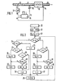
- FIG. 1 shows an overview of an electronically controlled injection system, in which the throttle valve position and the speed are processed as the most important operating parameters
- FIG. 2 shows a flow diagram as an exemplary embodiment of the invention
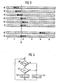
- FIG. 3 shows various examples of an irregular displacement of the idling position and its correction
- FIG. 4 shows a flow diagram to explain the operation of the idle detection.
- Figure 1 discloses the basic structure of an electrically controlled and preferably intermittent fuel injection system, based on signals of the speed and the throttle valve position angle. Such an arrangement is e.g. known from the aforementioned DE-OS 24 42 373.
- An internal combustion engine 10 receives intake air via an intake pipe 11 with a throttle valve 12 and has. an exhaust pipe 13.
- a speed sensor 14 detects the instantaneous speed of the crankshaft and, together with the position ⁇ of the throttle valve 12, determines an injection signal t p for an injection valve 15 assigned to the intake manifold 11
- other operating parameters such as the temperature and the lambda value are fed in. This is indicated by further inputs of the control unit 16.
- the positionoC of the throttle valve 12 is detected by a potentiometer 17 and supplied to the control unit 16 as a measured value M.
- the operating voltage of the potentiometer of, for example, drops over the entire slider path of the potentiometer 17. 5 volts off. If you divide the slider track into increments, then there are 256 increments in the case of 8 bits over the entire slider track. Since the mechanical adjustment range of the throttle valve 12 must lie within the adjustment range of the potentiometer, a specific data word results for the mechanical throttle valve stop A (idle position), which corresponds to a very small voltage or a small number of increments. In Figure 3, the mechanical stop A corresponds to nine increments.
- the idle position of the throttle valve can shift due to mechanical displacement of the potentiometer relative to the throttle valve, aging, wear of the stops and other error influencing variables. Through constant adaptation, the exact idle position should always be recognizable in a purely electronic manner.
- the mode of operation of the adaptation will be explained below with reference to FIGS. 2 and 3.
- the adaptation process starts 20 after the supply voltage (for example, ignition lock) is switched on, after the internal combustion engine has started and after the engine temperature has exceeded a certain threshold. This represents the beginning of an operating cycle, which occurs when the internal combustion engine or the supply voltage is switched off is ended. This is followed by an initialization 21 in which four memory cells or. Registers F, H, G and I are set to the value 0. Finally, in method step 22, the stored value of the idle position S LL is increased by one increment. The query step 23 now takes place, with which it is determined whether the measured value M present at the moment is greater than the stored idle value S LL .
- the supply voltage for example, ignition lock
- this condition applies, it is checked in query step 24 whether this measured value M lies outside a partial correction range which is limited by the value S LL on the one hand and S LL + 2 on the other. If this is the case, the condition M> S LL + 2 is fulfilled, the register F is set to the value 1 in step 25 and, after a delay time of 10 ms, a return to the query step 23 in a program loop. The cycle for querying the measured value M is specified in method step 26. The loop 23 to 26 is now run through until the measured value M falls within the correction range.
- steps 24, 27, 28 are carried out, it being determined in query step 28 that register F no longer has the value 1, so that method steps 32 and 26 lead to the query step 23 is returned.
- the described loop is run through without changes until the measured value M rises above the value S LL + 2 (query step 24), whereby in step 25 the register F is reset to the value 1.
- This loop 23, 24, 25, 26 is now run through until the measured value M no longer fulfills the condition of the query step 24.
- query step 23 If it is found in query step 23 that the measured value M is smaller than the stored idle value 8LL, it can be concluded immediately that this measured value M is at least closer to the actual idle value than the stored idle value does. The question of whether this measured value is close to the stored idle value is therefore superfluous.
- query step 34 it is therefore immediately checked whether the memory content of the register G> 2, which is not the case at this time.
- query step 35 it is then determined that the measured value M has not yet occurred, so that the registers G and I are set to the value 0 and the value 1 via method steps 36, 37 and via method step 26 to the query step again 23 is returned.
- the register G is incremented, since it was now determined in query step 35 that the measured value M has already occurred once.
- the loop 23, 34, 35, 38, 26 is now run through until the register G reaches the value 3, provided that the measured value M is retained in an identical manner.
- this measured value M which has occurred several times, is stored as a new idle value S LL and then the register G is reset to the value 0 and the register I is reset to the value 1.
- the measured value should correspond to the idling stop value A.
- the stored idle value is shown with double hatching in each case, while the two increments adjoining it on the right, which are simply hatched, represent the part of the correction range located to the right of the idle value.
- the stored idle value corresponds to the value 5. In this operating cycle, only the loop 23, 24, 25, 26 can be run through. In the subsequent operating cycle, the stored idle value increases in method step 22 by one increment (line b), but the loop 23, 24, 25, 26 is also run through again.
- condition 24 is no longer fulfilled, ie the measured value is now in the correction range. If - as described - an identical measured value M now occurs four times in an identical manner, this measured value is stored as a new idle value S LL in the same operating cycle as is shown in column d. In the subsequent fourth operating cycle, the new idle value is first incremented again in method step 22, as shown in column e. In query step 23 it is now determined that the measured value is smaller than the stored idle value, so that according to the above statements, after four identical occurrences, this measured value is stored as a new idle value, as shown in column f.
- the stored idle value can be increased by a number of increments instead of by one increment, which correspond to the maximum possible idle position of the throttle valve during warming up of the internal combustion engine.
- This number of increments corresponds, for example, to an angular position of 20 °.
- the engine temperature does not apply as a starting condition in process step 20.
- the throttle valve angle is set to a high idling value, which is then recorded and stored using process steps 34 to 39. If the idle angle slowly decreases as far as the engine temperature increases, the stored idle value follows this changing value by constant adaptation. At least one successfully completed adaptation process should be awaited for idle detection.
- FIG. 4 explains the logical decision in control unit 16 whether the idle position is present or not.
- query step 40 queries whether the current measured value M is smaller than the stored idle value S LL increased by three increments, that is to say whether the measured value lies within a hatched area according to FIG. 3. If this is not the case, no idle position is recognized in method step 41. If, on the other hand, the conditions apply, it is checked in query step 42 whether register I contains the value 1. This is only the case if at least one measured value that is below the idle value S LL was previously detected (see method steps 35 and 37).
- This query step 42 is for safe Detection of the idling is necessary if, in method step 22, an increase in the stored idling value S LL by a large amount at the beginning of an operating cycle has occurred, which is above the idling position during warm-up. On the other hand, if, according to FIG. 2, the stored idle speed S LL was increased by only one increment, the query step 42 can be omitted. In method step 43, the idle position is then identified when the condition of query step 40 and, if applicable, query step 42 is present.
- a characteristic curve or a characteristic map are selected by the measured values of the throttle valve position in the control unit 16, for example to determine the injection time, then after an adaptation, i.e. after a shift in the idle position compared to the originally entered value, a corresponding shift in the characteristic curve or the map.
- the newly determined and stored idle value is stored in a non-volatile or buffered memory and is available again when the internal combustion engine is started again.
- the described method is not limited to the detection of the idle position of a throttle valve, but is in principle suitable for the detection of an end position of any movable part which can carry out both linear and non-linear movements.
- the invention is not only limited to the detection of an initial position of such a movable part, but can also be used to detect the end position or any extreme displacement.
- potentiometers there are also other position detection devices, such as Optical, inductive and capacitive systems can be used.
- an initialization adaptation can preferably be provided, which is initiated, for example, by connecting a specific control unit pin to ground. This enables the control unit to recognize that an initialization adaptation is to be carried out. During this operating mode, the smallest measured value that occurs is interpreted as an idle value.
- the adaptation is not subject to any stationary or dynamic restrictions.
- the plausibility check can consist, for example, of whether the recorded measured values lie within a range that is at all possible as an extreme value position.
Abstract
Es wird ein Verfahren zur Erfassung einer Extremwertposition eines beweglichen Teils durch ein Positionserfassungsorgan (17) vorgeschlagen, insbesondere zur Erfassung der Leerlaufposition der Drosselklappe (12) einer Brennkraftmaschine (10) mit Hilfe eines Potentiometers. Dabei wird ein der Extremwertposition entsprechnder gespeicherter Wert (Extremwert) bei Erfassung abweichender gemessener Werte korrigiert, sofern diese abweichenden gemessenen Werte in einem Korrekturbereich um den Extremwert herum liegen. Der Bewegungsbereich des beweglichen Teils muß innerhalb des durch das Positionserfassungsorgan (17) erfaßbaren Bereichs liegen. Nach Erfassung einer festgelegten Anzahl identischer Meßwerte im Korrekturbereich während eines Betriebszyklus wird ein solcher Meßwert als neuer Extremwert gespeichert. Dieser neue Extremwert wird zyklisch, vorzugsweise vor jedem Betriebszyklus um einem vorgegebenen Wert von der äußersten Position weg verändert, um die Adaption dynamisch zu gestalten. Dieses Verfahren weist eine sehr kleine Hysterese bei hoher Genauigkeit der Erfassung der Extremwertposition auf, wobei selbst bei irregulären Betriebsbedingungen nach kurzer Zeit wieder die volle Funktionsfähigkeit erreicht wird.A method for detecting an extreme value position of a moving part by a position detection element (17) is proposed, in particular for detecting the idle position of the throttle valve (12) of an internal combustion engine (10) with the aid of a potentiometer. A stored value (extreme value) corresponding to the extreme value position is corrected when deviating measured values are detected, provided that these deviating measured values lie in a correction range around the extreme value. The range of motion of the movable part must lie within the range that can be detected by the position detection element (17). After a specified number of identical measured values have been recorded in the correction range during an operating cycle, such a measured value is stored as a new extreme value. This new extreme value is changed cyclically, preferably before each operating cycle, by a predetermined value from the outermost position in order to make the adaptation dynamic. This method has a very small hysteresis with high accuracy of the detection of the extreme value position, the full functionality being achieved again after a short time even under irregular operating conditions.
Description
Die Erfindung geht aus von einem Verfahren nach der Gattung des Hauptanspruchs, insbesondere zur Erfassung der Leerlaufposition der Drosselklappe einer Brennkraftmaschine.The invention is based on a method according to the type of the main claim, in particular for detecting the idle position of the throttle valve of an internal combustion engine.
Aus der DE-OS 24 42 373 ist eine elektrisch gesteuerte, intermittierend arbeitende Kraftstoffeinspritzanlage mit einer Einspritzsignalerzeugung bekannt, die von der Drehzahl und der Drosselklappenstellung ausgeht. Die Drosselklappenstellung wird dort mittels eines Potentiometers erfaßt. Im Hinblick auf eine optimale Kraftstoffzumessung ist es erforderlich, daß insbesondere im Bereich relativ kleiner Drosselklappenöffnungsvinkel die Drosselklappenposition sehr exakt erfaßt wird. Z.B. muß zur Einstellung des Leerlaufs eine Leerlaufstellung der Drosselklappe erkannt werden, wozu üblicherweise ein Leerlaufschalter verwendet wird. Der Leerlaufanschlag unterliegt jedoch Änderungen sowohl durch Einstellung.der Leerlaufdrehzahl, als auch durch mechanische Abnützung des Anschlages. Die . Leerlaufposition der Drosselklappe muß jedoch innerhalb eines sehr kleinen Winkelbereiches von ca. 0,3° erkannt werden, da nur dort die Luftflüsse klein genug sind, um die Momentenänderung beim Zu- und Abschalten des Kraftstoffes durch die Schubabschaltfunktion in erträglichen Grenzen zu halten.From DE-OS 24 42 373 an electrically controlled, intermittently operating fuel injection system with an injection signal generation is known, which is based on the speed and the throttle valve position. The throttle valve position is detected there using a potentiometer. With a view to optimum fuel metering, it is necessary that the throttle valve position is detected very precisely, particularly in the area of relatively small throttle valve opening angles. For example, to set the idle, an idle position of the throttle valve must be recognized, for which purpose an idle switch is usually used. However, the idle stop is subject to changes both by adjusting the idle speed and by mechanical wear on the stop. The . However, the idle position of the throttle valve must be within a very small angular range of approx. 0.3 ° can be recognized, because only there the air flows are small enough to keep the torque change when switching the fuel on and off by the overrun fuel cut-off function within tolerable limits.
Aus der DE-OS 34 28 87.9 ist ein digitales Verfahren zur Leerlauferkennung bekannt, bei dem die Schleiferbahn des als Potentiometer ausgebildeten Positionserfassungsorgans in Inkremente unterteilt ist. Ein gespeicherter Grenzwert wird in Abhängigkeit gemessener Werte mit einer bestimmten Zeitkonstanten nachgeführt. Zur Nachführung muß jedoch ein konstanter Winkelhub zwischen Minimalwert und Maximalwert in Betracht gezogen werden, wobei dann dieser gesamte Meßbereich nachgeführt wird. Insbesondere für nichtlineare Potentiometer ist dieses Verfahren wenig geeignet.From DE-OS 34 28 87.9 a digital method for idle detection is known, in which the wiper track of the position sensing element designed as a potentiometer is divided into increments. A stored limit value is updated with a specific time constant depending on the measured values. For tracking, however, a constant angular stroke between the minimum and maximum values must be taken into account, in which case this entire measuring range is then tracked. This method is not particularly suitable for non-linear potentiometers.
Der Erfindung liegt die Aufgabe zugrunde, das im oben angegebenen Stand der Technik bekannte Verfahren so zu verbessern, daß bei hoher Genauigkeit und schneller Adaption, auch bei irregulären Betriebsbedingungen und großen Winkeldifferenzen, ein Extremwert isoliert adaptiert werden kann, ohne daß der entgegengesetzt liegende Extremwert einen Einfluß ausüben könnte.The invention has for its object to improve the known in the prior art method so that with high accuracy and rapid adaptation, even with irregular operating conditions and large angle differences, an extreme value can be adapted isolated, without the opposite extreme value one Could exert influence.
Das erfindungsgemäße Verfahren mit den kennzeichnenden Merkmalen des Hauptanspruchs löst diese Aufgabe und hat den Vorteil, daß durch eine sehr geringe Hysterese und sichere Erkennung der Leerlaufposition eine exakte Einstellung und Erkennung dieser Position gewährleistet ist.The inventive method with the characterizing features of the main claim solves this problem and has the advantage that an exact setting and detection of this position is ensured by a very low hysteresis and reliable detection of the idle position.
Durch die in den Unteransprüchen angegebenen Merkmale sind vorteilhafte Weiterbildungen und Verbesserungen des im Hauptanspruch angegebenen Verfahrens möglich.Advantageous developments and improvements of the method specified in the main claim are possible due to the features specified in the subclaims.
Ein Ausführungsbeispiel der Erfindung ist in der Zeichnung dargestellt und in der nachfolgenden Beschreibung näher erläutert. Es zeigen Figur 1 eine Übersichtsdarstellung einer elektronisch gesteuerten Einspritzanlage, bei der als wichtigste Betriebskenngrößen die Drosselklappenposition und die Drehzahl verarbeitet werden, Figur 2 als Ausführungsbeispiel der Erfindung ein Flußdiagramm, Figur 3 verschiedene Beispiele einer irregulären Verschiebung der Leerlaufposition und deren Korrektur und Figur 4 ein Flußdiagramm zur Erläuterung der Wirkungsweise der Leerlauferkennung.An embodiment of the invention is shown in the drawing and explained in more detail in the following description. FIG. 1 shows an overview of an electronically controlled injection system, in which the throttle valve position and the speed are processed as the most important operating parameters, FIG. 2 shows a flow diagram as an exemplary embodiment of the invention, FIG. 3 shows various examples of an irregular displacement of the idling position and its correction, and FIG. 4 shows a flow diagram to explain the operation of the idle detection.
Figur 1 offenbart die Grundstruktur einer elektrisch gesteuerten und vorzugsweise intermittierend arbeitenden Kraftstoffeinspritzanlage, ausgehend von Signalen der Drehzahl und des Drosselklappenstellungswinkels. Eine derartige Anordnung ist z.B. aus der bereits eingangs erwähnten DE-OS 24 42 373 bekannt.Figure 1 discloses the basic structure of an electrically controlled and preferably intermittent fuel injection system, based on signals of the speed and the throttle valve position angle. Such an arrangement is e.g. known from the aforementioned DE-OS 24 42 373.
Eine Brennkraftmaschine 10 erhält Ansaugluft über ein Ansaugrohr 11 mit einer Drosselklappe 12 und besitzt . eine Abgasleitung 13. Ein Drehzahlsensor 14 erfaßt die Augenblicksdrehzahl der Kurbelwelle und bestimmt zusammen mit der Position α der Drosselklappe 12 ein Einspritzsignal tp für ein dem Ansaugrohr 11 zugeordnetes Einspritzventil 15. In ein Steuergerät 16 für die elektronische Kraftstoffeinspritzung werden in der Regel außer der Drehzahl und der Drosselklappenposition noch weitere Betriebskenngrößen, wie z.B. die Temperatur und der Lambda-Wert eingespeist. Dies ist mit weiteren Eingängen des Steuergeräts 16 angedeutet.An
Die PositionoC der Drosselklappe 12 wird dabei über ein Potentiometer 17 erfaßt und als Meßwert M dem Steuergerät 16 zugeführt. Über der gesamten Schleiferbahn des Potentiometers 17 fällt dabei die Betriebsspannung des Potentiometers von z.B. 5 Volt ab. Unterteilt man die Schleiferbahn in Inkremente, dann ergeben sich im Falle von 8 Bit über der gesamten Schleiferbahn 256 Inkremente. Da der mechanische Verstellbereich der Drosselklappe 12 innerhalb des Verstellbereichs des Potentiometers liegen muß, ergibt sich für den mechanischen Drosselklappenanschlag A (Leerlaufposition) ein bestimmtes Datenwort, das einer sehr kleinen Spannung, bzw. einer geringen Anzahl von Inkremten entspricht. In Figur 3 entspricht der mechanische Anschlag A neun Inkrementen. Durch mechanische Verschiebung des Potentiometers relativ zur Drosselklappe, durch Alterung, durch Abnutzung der Anschläge und durch weitere Fehlereinflußgrößen kann sich die Leerlaufposition der Drosselklappe verschieben. Durch ständige Adaption soll auf rein elektronische Weise immer die exakte Leerlaufposition erkannt werden können.The positionoC of the
Die Wirkungsweise der Adaption soll im folgenden anhand der Figuren 2 und 3 erläutert werden. Der Start 20 des Adaptionsverfahrens erfolgt nach Einschalten der Versorgungsspannung (z.B. Zündschloß), nach erfolgtem Start der Brennkraftmaschine und nachdem die Motortemperatur eine bestimmte Schwelle überschritten hat. Dies stellt den Beginn eines Betriebszyklus dar, der durch Abschaltung der Brennkraftmaschine bzw. der Versorgungsspannung beendet wird. Danach erfolgt eine Initialisierung 21, bei der vier Speicherzellen bzv. Register F, H, G und I auf den Wert 0 gesetzt werden. Schließlich wird im Verfahrensschritt 22 der gespeicherte Wert der Leerlaufposition SLL um ein Inkrement erhöht. Jetzt erfolgt der Abfrageschritt 23, mit dem festgestellt wird, ob der im Augenblick vorliegende Meßwert M größer als der gespeicherte Leerlaufwert S LL ist.The mode of operation of the adaptation will be explained below with reference to FIGS. 2 and 3. The adaptation process starts 20 after the supply voltage (for example, ignition lock) is switched on, after the internal combustion engine has started and after the engine temperature has exceeded a certain threshold. This represents the beginning of an operating cycle, which occurs when the internal combustion engine or the supply voltage is switched off is ended. This is followed by an initialization 21 in which four memory cells or. Registers F, H, G and I are set to the
Trifft diese Bedingung zu, so wird im Abfrageschritt 24 geprüft, ob dieser Meßwert M außerhalb.eines Teilkorrekturbereichs liegt, der durch den Wert SLL einerseits und SLL+2 andererseits begrenzt wird. Trifft dies zu, ist also die Bedingung M > SLL+2 erfüllt, so wird im Schritt 25 das Register F auf den Wert 1 gesetzt und nach einer Verzögerungszeit von 10 ms in einer Programmschleife wieder zum Abfrageschritt 23 zurückgekehrt. Der Takt für die Abfrage des Meßwerts M wird im Verfahrensschritt 26 vorgegeben. Die Schleife 23 bis 26 wird nun solange durchlaufen, bis der Meßwert M in den Korrekturbereich fällt.If this condition applies, it is checked in
Ist somit die Bedingung des Abfrageschritts 24 nicht mehr erfüllt, so wird im Abfrageschritt 27 geprüft, ob der Registerwert des Registers H > 2 ist. Zu diesem Zeitpunkt ist diese Bedingung nicht erfüllt, so daß nunmehr im Abfrageschritt 28 geprüft wird, ob das Register F den Wert 1 aufweist, was jetzt zutrifft. Nun wird im Abfrageschritt 29 geprüft, ob der Meßwert M bereits zuvor schon einmal aufgetreten ist (Mi = Mi-1). Da dies nicht der Fall ist, wird das Register H im Schritt 30 auf den Wert 0 gesetzt - der Wert 0 liegt zu diesem Zeitpunkt ohnehin vor - und zum Abfrageschritt 23 nach der vorgegebenen Taktzeit zurückgekehrt. Nun erfolgt ein erneuter Durchlauf der Schritte 23, 24, 27, 28 und 29, sofern die entsprechenden Bedingungen noch vorliegen. Im Abfrageschritt 29 wird jetzt festgestellt, daß der Meßwert M schon einmal auftrat, so daß jetzt im Verfahrensschritt 31 das Register H um den Wert 1 inkrementiert wird. Danach wird im Verfahrensschritt 32 das Register F auf den Wert 0 gesetzt und nach der vorgesehenen Taktzeit zum Abfrageschritt 23 zurückgekehrt.If the condition of the
Liegt der gleiche Meßwert M jetzt immer noch vor., so werden die Schritte 24, 27, 28 durchlaufen, wobei im Abfrageschritt 28 festgestellt wird, daß das Register F nicht mehr den Wert 1 aufweist, so daß über die Verfahrensschritte 32 und 26 zum Abfrageschritt 23 zurückgekehrt wird. Solange sich der Meßwert M nicht ändert, wird die beschriebene Schleife ohne Änderungen durchlaufen, bis der Meßwert M über den Wert SLL+2 ansteigt (Abfrageschritt 24) wodurch im Verfahrensschritt 25 das Register F wieder auf den Wert 1 gesetzt wird. Nunmehr wird diese Schleife 23, 24, 25, 26 solange durchlaufen, bis der Meßwert M die Bedingung des Abfrageschritts 24 nicht mehr erfüllt.If the same measured value M is still available,
Zur weiteren Inkrementierung des Registers H im Verfahrensschritt 31 ist es erforderlich, daß die Bedingung des Abfrageschritts 29 erfüllt ist, daß also der erfaßte Meßwert M bereits vorher identisch erfaßt wurde. In diesem Fall kann das Register H um 1 auf nunmehr den Wert 2 inkrementiert werden.For further incrementation of the register H in
Um die Bedingung des Abfrageschritts 27 (H > 2) zu erfüllen, ist es somit erforderlich, daß nacheinander die Schleife 1 (23, 24, 25, 26), die Schleife 2 (23, 24, 27, 28, 29, 30, 26), die Schleife 3 (23, 24, 27, 28, 29, 31, 32, 26) und danach nochmals im doppelten Wechselspiel die Schleife 1 und die Schleife 3 durchlaufen werden. Wenn also mit anderen Worten der Meßwert M viermal identisch nachgewiesen wird, wobei zuletzt dreimal jeweils.dazwischen mindestes ein Meßwert auftreten muß, der die Abfragebedingung 24 erfüllt, dann wird im Verfahrensschritt 33 dieser Meßwert M als neuer Leerlaufwert SLL gespeichert. Da danach im Verfahrensschritt 30 das Register H wieder auf den Wert 0 gesetzt wird, muß der gesamte Verfahrensablauf wiederholt werden, um den Wert SLL erneut zu verändern. Es wird dabei von der Überlegung ausgegangen, daß ein Meßwert, der mehrmals in identischer Weise in der Nähe des gespeicherten Leerlaufwerts auftritt, der tatsächliche Leerlaufwert sein muß.In order to fulfill the condition of query step 27 (H> 2), it is therefore necessary that the loop 1 (23, 24, 25, 26), the loop 2 (23, 24, 27, 28, 29, 30, 26), loop 3 (23, 24, 27, 28, 29, 31, 32, 26) and then loop 1 and loop 3 again in double interplay. In other words, if the measured value M is detected identically four times, with the last three times, at least one measurement value must occur in between that fulfills the
Wird beim Abfrageschritt 23 festgestellt, daß der Meßwert M kleiner als der gespeicherte Leerlaufwert 8LL ist, so kann hieraus sofort geschlossen werden, daß dieser Meßwert M dem tatsächlichen Leerlaufwert zumindest näher kommt, als dies der gespeicherte Leerlaufwert tut. Die Abfrage, ob sich dieser Meßwert in der Nähe des gespeicherten Leerlaufwerts befindet, ist daher überflüssig. Im Abfrageschritt 34 wird daher sofort geprüft, ob der Speicherinhalt des Registers G > 2 ist, was zu diesem Zeitpunkt nicht zutrifft. Im Abfrageschritt 35 wird danach festgestellt, daß der erfaßte Meßwert M zuvor noch nicht aufgetreten ist, so daß über die Verfahrensschritte 36, 37 die Register G und I auf den Wert 0 bzw. den Wert 1 gesetzt werden und über den Verfahrensschritt 26 wieder zum Abfrageschritt 23 zurückgekehrt wird. Im nächsten Durchlauf wird nach den Abfrageschritten 23, 34, 35, im Verfahrensschritt 38 das Register G inkrementiert, da jetzt im Abfrageschritt 35 festgestellt wurde, daß der Meßwert M bereits schon einmal aufgetreten ist. Die Schleife 23, 34, 35, 38, 26 wird nun solange durchlaufen, bis das Register G den Wert 3 erreicht, immer vorausgesetzt, der Meßwert M bleibt in identischer Weise erhalten. Jetzt wird im Verfahrensschritt 39 dieser mehrmals aufgetretene Meßwert M als neuer Leerlaufwert SLL gespeichert und danach das Register G wieder auf den Wert 0 und das Register I wieder auf den Wert 1 gesetzt.If it is found in
In Figur 3 soll der Meßwert dem Leerlaufanschlagwert A entsprechen. Der gespeicherte Leerlaufwert ist jeweils doppelt schraffiert dargestellt, während die beiden rechts daran anschließenden Inkremente, die einfach schraffiert dargestellt sind, den rechts vom Leerlaufwert befindlichen Teil des Korrekturbereichs darstellen.In Figure 3, the measured value should correspond to the idling stop value A. The stored idle value is shown with double hatching in each case, while the two increments adjoining it on the right, which are simply hatched, represent the part of the correction range located to the right of the idle value.
In Zeile a entspricht der gespeicherte Leerlaufwert dem Wert 5. In diesem Betriebszyklus kann somit lediglich die Schleife 23, 24, 25, 26 durchlaufen werden. Im darauffolgenden Betriebszyklus erhöht sich zwar der gespeicherte Leerlaufwert im Verfahrensschritt 22 um ein Inkrement (Zeile b), jedoch wird auch jetzt wiederum die Schleife 23, 24, 25, 26 durchlaufen.In line a, the stored idle value corresponds to the
In dem in Spalte c dargestellten dritten Betriebszyklus ist die Bedingung 24 nicht mehr erfüllt, d.h., der Meßwert befindet sich jetzt im Korrekturbereich. Tritt nunmehr - wie beschrieben - ein gleicher Meßwert M viermal in identischer Weise auf, dann wird dieser Meßwert als neuer Leerlaufwert SLL im gleichen Betriebszyklus gespeichert, wie dies in Spalte d dargestellt ist. Im darauffolgenden vierten Betriebszyklus wird zunächst wiederum der neue Leerlaufwert im Verfahrensschritt 22 inkrementiert, wie dies in Spalte e dargestellt ist. Im Abfrageschritt 23 wird jetzt festgestellt, daß der Meßwert kleiner als der gespeicherte Leerlaufwert ist, so daß gemäß obigen Ausführungen nach viermaligem identischen Auftreten dieser Meßwert als neuer Leerlaufwert gespeichert wird, wie dies in Spalte f dargestellt ist.In the third operating cycle shown in column c,
Wie die Spalten g und h zeigen, wird bei Unterschreitung des gespeicherten Leerlaufwerts durch den Meßwert im gleichen Betriebszyklus noch eine neue Festlegung des gespeicherten Leerlaufverts vorgenommen, unabhängig wie groß die Abweichung vom bisherigen Leerlaufwert ist.As columns g and h show, if the stored idle value is undershot by the measured value in the same operating cycle, the stored idle time is determined anew, regardless of how large the deviation from the previous idle value is.
Als Alternative zum Verfahrensschritt 22 kann zu Beginn eines Betriebszyklus der gespeicherte Leerlaufwert statt um ein Inkrement um eine Anzahl von Inkrementen erhöht werden, die der maximal möglichen Leerlaufstellung der Drosselklappe während des Aufwärmens der Brennkraftmaschine entsprechen. Diese Anzahl von Inkrementen entspricht dabei beispielsweise einer Winkelstellung von 20°. In diesem Fall entfällt natürlich die Motortemperatur als Startbedingung im Verfahrensschritt 20. Zu Beginn des Warmlaufs stellt sich der Drosselklappenvinkel auf einen hohen Leerlaufwert ein, der dann mittels der Verfahrensschritte 34 bis 39 erfaßt und eingespeichert wird. Wenn dann mit zunehmender Motortemperatur der Leerlaufvinkel langsam bis zum Anschlag zurückgeht, folgt der gespeicherte Leerlaufwert durch ständige Adaption diesem sich verändernden Wert. Für die Leerlauferkennung sollte dabei mindestens ein erfolgreich abgeschlossener Adaptionsvorgang abgewartet werden.As an alternative to method step 22, at the beginning of an operating cycle, the stored idle value can be increased by a number of increments instead of by one increment, which correspond to the maximum possible idle position of the throttle valve during warming up of the internal combustion engine. This number of increments corresponds, for example, to an angular position of 20 °. In this case, of course, the engine temperature does not apply as a starting condition in
In Figur 4 ist die logische Entscheidung im Steuergerät 16 erläutert, ob die Leerlaufstellung vorliegt oder nicht. Dazu wird im Abfrageschritt 40 abgefragt, ob der augenblicklich vorliegende Meßwert M kleiner als der um drei Inkremente erhöhte gespeicherte Leerlaufwert SLL ist, also ob der Meßwert innerhalb eines schraffierten Bereichs gemäß Figur 3 liegt. Trifft dies nicht zu, so wird im Verfahrensschritt 41 keine Leerlaufstellung erkannt. Trifft die Bedingungen dagegen zu, so wird im Abfrageschritt 42 geprüft, ob das Register I den Wert 1 beinhaltet. Dies ist nur dann der Fall, wenn wenigstens ein Meßwert zuvor erkannt wurde, der unterhalb dem Leerlaufwert SLL liegt (siehe Verfahrensschritte 35 und 37). Dieser Abfrageschritt 42 ist zur sicheren Erkennung des Leerlaufs erforderlich, wenn im Verfahrensschritt 22 zu Beginn eines Betriebszyklus eine Erhöhung des gespeicherten Leerlaufwerts SLL um einen großen Betrag erfolgt ist, der über der Leerlaufstellung während des Warmlaufs liegt. Wurde dagegen gemäß Figur 2 der gespeicherte Leerlauf SLL nur um ein Inkrement erhöht, so kann der Abfrageschritt 42 entfallen. Im Verfahrensschritt 43 erfolgt dann bei Vorliegen der Bedingung des Abfrageschritts 40 und gegebenenfalls des Abfrageschritts 42 die Erkennung der Leerlaufstellung.FIG. 4 explains the logical decision in
Sofern durch die Meßwerte der Drosselklappenstellung im Steuergerät 16 die Werte einer Kennlinie oder eines Kennfeldes angewählt werden, beispielsweise zur Festlegung der Einspritzzeit, so muß nach einer Adaption, also nach einer Verschiebung der Leerlaufstellung gegenüber dem ursprünglich eingegebenen Wert natürlich auch eine entsprechende Verschiebung der Kennlinie bzw. des Kennfeldes erfolgen. Der jeweils neu festgelegte und gespeicherte Leerlaufwert wird in einem nichtflüchtigen bzw. gepufferten Speicher festgehalten und steht bei einem erneuten Start der Brennkraftmaschine wieder sofort zur Verfügung.If the values of a characteristic curve or a characteristic map are selected by the measured values of the throttle valve position in the
Selbstverständlich ist das beschriebene Verfahren nicht auf die Erfassung der Leerlaufposition einer Drosselklappe beschränkt, sondern ist prinzipiell zur Erfassung einer Endstellung eines beliebigen beweglichen Teils geeignet, das sowohl lineare, wie auch nichtlineare Bewegungen ausführen kann. Des weiteren ist die Erfindung nicht nur auf die Erfassung einer Anfangsposition eines solchen beweglichen Teils beschränkt, sondern kann auch zur Erfassung der Endposition, bzw. jeder Extremvertposition verwendet werden. Schließlich sind prinzipiell neben Potentiometern auch andere Positionserfassungsorgane, wie z.B. optische, induktive und kapazitive Systeme verwendbar.Of course, the described method is not limited to the detection of the idle position of a throttle valve, but is in principle suitable for the detection of an end position of any movable part which can carry out both linear and non-linear movements. Furthermore, the invention is not only limited to the detection of an initial position of such a movable part, but can also be used to detect the end position or any extreme displacement. Finally, in addition to potentiometers, there are also other position detection devices, such as Optical, inductive and capacitive systems can be used.
Liegt beim ersten Betriebsbeginn noch kein gespeicherter Extremwert vor oder trat eine Störung oder Löschung dieses Extremwerts ein, so kann vorzugsweise eine Initialisierungsadaption vorgesehen werden, die beispielsweise dadurch eingeleitet wird, daß ein bestimmter Steuergeräte-Pin an Masse gelegt wird. Dadurch kann das Steuergerät erkennen, daß eine Initialisierungsadaption vorgenommen werden soll. Während dieser Betriebsart wird der jeweils auftretende kleinste Meßwert als Leerlaufwert interpretiert. Die Adaption unterliegt dabei außer einer Plausibilitätsprüfung keiner stationären oder dynamischen Beschränkung. Die Plausibilitätsprüfung kann beispielsweise darin bestehen, ob die erfaßten Meßwerte innerhalb eines Bereichs liegen, der überhaupt als Extremwertposition in Frage kommt.If there is no stored extreme value at the first start of operation or if this extreme value has been disturbed or deleted, an initialization adaptation can preferably be provided, which is initiated, for example, by connecting a specific control unit pin to ground. This enables the control unit to recognize that an initialization adaptation is to be carried out. During this operating mode, the smallest measured value that occurs is interpreted as an idle value. Apart from a plausibility check, the adaptation is not subject to any stationary or dynamic restrictions. The plausibility check can consist, for example, of whether the recorded measured values lie within a range that is at all possible as an extreme value position.
Claims (7)
Applications Claiming Priority (2)
| Application Number | Priority Date | Filing Date | Title |
|---|---|---|---|
| DE19843445983 DE3445983A1 (en) | 1984-12-17 | 1984-12-17 | METHOD FOR DETECTING AN EXTREME VALUE POSITION OF A MOVING PART |
| DE3445983 | 1984-12-17 |
Publications (3)
| Publication Number | Publication Date |
|---|---|
| EP0185945A2 true EP0185945A2 (en) | 1986-07-02 |
| EP0185945A3 EP0185945A3 (en) | 1987-02-04 |
| EP0185945B1 EP0185945B1 (en) | 1989-03-15 |
Family
ID=6252994
Family Applications (1)
| Application Number | Title | Priority Date | Filing Date |
|---|---|---|---|
| EP85114945A Expired EP0185945B1 (en) | 1984-12-17 | 1985-11-26 | Moving part extreme position sensing device |
Country Status (4)
| Country | Link |
|---|---|
| US (1) | US4722313A (en) |
| EP (1) | EP0185945B1 (en) |
| JP (1) | JPS61145406A (en) |
| DE (2) | DE3445983A1 (en) |
Cited By (7)
| Publication number | Priority date | Publication date | Assignee | Title |
|---|---|---|---|---|
| EP0210419A1 (en) * | 1985-07-12 | 1987-02-04 | WEBER S.r.l. | System for automatically defining the minimum setting of an accelerator-controlled valve for supplying an internal combustion engine |
| FR2616848A1 (en) * | 1987-06-16 | 1988-12-23 | Renault | Method for recognising the "foot off" position for a vehicle with electronic injection or carburation |
| EP0297433A2 (en) * | 1987-07-03 | 1989-01-04 | Hitachi, Ltd. | Electronically-controlled fuel injection system for internal combustion engines |
| EP0264384B1 (en) | 1986-04-17 | 1990-09-05 | Robert Bosch Gmbh | Process for compensating tolerances of a position transmitter signal |
| WO1990011442A1 (en) * | 1989-03-25 | 1990-10-04 | Robert Bosch Gmbh | Process for determining at least one end position of an adjusting device in a motor vehicle |
| WO1991004399A1 (en) * | 1989-09-21 | 1991-04-04 | Robert Bosch Gmbh | Process for controlling the air supply to an internal combustion engine of a motor vehicle |
| DE4335239C1 (en) * | 1993-10-15 | 1994-12-01 | Vdo Schindling | Method for positioning an actuator |
Families Citing this family (9)
| Publication number | Priority date | Publication date | Assignee | Title |
|---|---|---|---|---|
| JPH081148B2 (en) * | 1988-11-30 | 1996-01-10 | 富士重工業株式会社 | Engine throttle valve fully closed state detection device |
| JP2542709B2 (en) * | 1989-11-09 | 1996-10-09 | 三菱電機株式会社 | Engine throttle opening detection device |
| JP3634872B2 (en) * | 1992-09-30 | 2005-03-30 | 株式会社デンソー | Throttle fully closed detection device |
| DE4336038A1 (en) * | 1993-10-22 | 1995-04-27 | Vdo Schindling | Method for operating a throttle valve adjustment device |
| DE4339693A1 (en) * | 1993-11-22 | 1995-05-24 | Bosch Gmbh Robert | Internal combustion engine control method |
| DE4340372A1 (en) * | 1993-11-26 | 1995-06-01 | Vdo Schindling | Recognition of idling condition of IC engine |
| US5415144A (en) * | 1994-01-14 | 1995-05-16 | Robertshaw Controls Company | Throttle position validation method and apparatus |
| JP3769083B2 (en) * | 1996-10-07 | 2006-04-19 | 本田技研工業株式会社 | Failure determination device for idle speed control device |
| US6751567B2 (en) * | 2001-11-26 | 2004-06-15 | Ford Global Technologies, Llc | Electronic throttle plate index position determination for improved airflow correlation over various temperature conditions |
Citations (4)
| Publication number | Priority date | Publication date | Assignee | Title |
|---|---|---|---|---|
| US4336593A (en) * | 1979-02-26 | 1982-06-22 | Nissan Motor Company, Ltd. | Data processing system for electronic control of automotive vehicle devices with noise prevention |
| US4359894A (en) * | 1980-01-31 | 1982-11-23 | Nissan Motor Company, Limited | Throttle valve most closed position sensing system |
| GB2113426A (en) * | 1982-01-14 | 1983-08-03 | Honda Motor Co Ltd | Method for detecting opening of a throttle valve in a fully closed position in an internal combustion engine |
| WO1986003258A1 (en) * | 1984-11-19 | 1986-06-05 | Robert Bosch Gmbh | Adjustment method for a position detection member, particularly in a motor vehicle |
Family Cites Families (2)
| Publication number | Priority date | Publication date | Assignee | Title |
|---|---|---|---|---|
| JPS57188753A (en) * | 1981-05-08 | 1982-11-19 | Honda Motor Co Ltd | Fuel closing reference positional automatic compensator for exhaust gas recirculating valve in exhaust gas recirculating control equipment |
| US4586403A (en) * | 1984-01-05 | 1986-05-06 | General Motors Corporation | Adaptively calibrated sensing mechanism for an engine demand device |
-
1984
- 1984-12-17 DE DE19843445983 patent/DE3445983A1/en not_active Withdrawn
-
1985
- 1985-11-22 JP JP60261627A patent/JPS61145406A/en active Pending
- 1985-11-26 EP EP85114945A patent/EP0185945B1/en not_active Expired
- 1985-11-26 DE DE8585114945T patent/DE3568827D1/en not_active Expired
- 1985-12-13 US US06/809,015 patent/US4722313A/en not_active Expired - Lifetime
Patent Citations (4)
| Publication number | Priority date | Publication date | Assignee | Title |
|---|---|---|---|---|
| US4336593A (en) * | 1979-02-26 | 1982-06-22 | Nissan Motor Company, Ltd. | Data processing system for electronic control of automotive vehicle devices with noise prevention |
| US4359894A (en) * | 1980-01-31 | 1982-11-23 | Nissan Motor Company, Limited | Throttle valve most closed position sensing system |
| GB2113426A (en) * | 1982-01-14 | 1983-08-03 | Honda Motor Co Ltd | Method for detecting opening of a throttle valve in a fully closed position in an internal combustion engine |
| WO1986003258A1 (en) * | 1984-11-19 | 1986-06-05 | Robert Bosch Gmbh | Adjustment method for a position detection member, particularly in a motor vehicle |
Cited By (9)
| Publication number | Priority date | Publication date | Assignee | Title |
|---|---|---|---|---|
| EP0210419A1 (en) * | 1985-07-12 | 1987-02-04 | WEBER S.r.l. | System for automatically defining the minimum setting of an accelerator-controlled valve for supplying an internal combustion engine |
| EP0264384B1 (en) | 1986-04-17 | 1990-09-05 | Robert Bosch Gmbh | Process for compensating tolerances of a position transmitter signal |
| FR2616848A1 (en) * | 1987-06-16 | 1988-12-23 | Renault | Method for recognising the "foot off" position for a vehicle with electronic injection or carburation |
| EP0297433A2 (en) * | 1987-07-03 | 1989-01-04 | Hitachi, Ltd. | Electronically-controlled fuel injection system for internal combustion engines |
| EP0297433A3 (en) * | 1987-07-03 | 1989-07-05 | Hitachi, Ltd. | Electronically-controlled fuel injection system for internal combustion engines |
| WO1990011442A1 (en) * | 1989-03-25 | 1990-10-04 | Robert Bosch Gmbh | Process for determining at least one end position of an adjusting device in a motor vehicle |
| WO1991004399A1 (en) * | 1989-09-21 | 1991-04-04 | Robert Bosch Gmbh | Process for controlling the air supply to an internal combustion engine of a motor vehicle |
| DE4335239C1 (en) * | 1993-10-15 | 1994-12-01 | Vdo Schindling | Method for positioning an actuator |
| US5854545A (en) * | 1993-10-15 | 1998-12-29 | Vdo Adolf Schindling Ag | Method for the positioning of an actuator |
Also Published As
| Publication number | Publication date |
|---|---|
| US4722313A (en) | 1988-02-02 |
| DE3568827D1 (en) | 1989-04-20 |
| DE3445983A1 (en) | 1986-06-19 |
| EP0185945A3 (en) | 1987-02-04 |
| JPS61145406A (en) | 1986-07-03 |
| EP0185945B1 (en) | 1989-03-15 |
Similar Documents
| Publication | Publication Date | Title |
|---|---|---|
| EP0185945B1 (en) | Moving part extreme position sensing device | |
| EP0416270B1 (en) | Method and apparatus to control and regulate an engine with self-ignition | |
| DE2633617C2 (en) | Method and device for determining setting variables in an internal combustion engine, in particular the duration of fuel injection pulses, the ignition angle, the exhaust gas recirculation rate | |
| EP0051723B1 (en) | Method of operating an electronic control system for an internal-combustion engine | |
| DE4208002B4 (en) | System for controlling an internal combustion engine | |
| DE2743664A1 (en) | ELECTRONIC IGNITION TIME ADVANCED SETTING DEVICE | |
| DE69827722T2 (en) | Device for controlling the fuel injection of a direct injection gasoline engine and method therefor. | |
| DE19647161A1 (en) | Control arrangement for IC engine ignition timing and fuel injection | |
| DE2245029B2 (en) | Method and device for exhaust gas detoxification from internal combustion engines | |
| DE3343481C2 (en) | ||
| DE19749815B4 (en) | Method and device for determining the amount of fuel injected | |
| EP0170834B1 (en) | Measuring method for motor vehicles | |
| DE2247656A1 (en) | METHOD AND DEVICE FOR EXHAUST GAS DETOXIFICATION FROM INTERNAL COMBUSTION MACHINERY | |
| DE4029537A1 (en) | METHOD AND DEVICE FOR CONTROLLING AND / OR REGULATING AN OPERATING SIZE OF AN INTERNAL COMBUSTION ENGINE | |
| DE4401828A1 (en) | Prediction of load requirement in control of internal combustion engine | |
| DE4041505C2 (en) | Method and device for detecting a variable size for an internal combustion engine on a motor vehicle | |
| DE4308541A1 (en) | Method and device for controlling and / or regulating an actuator | |
| DE19857971A1 (en) | Controlling an IC engine esp. for IC engine with common rail fuel injection system so that at least one pump delivers fuel in storage | |
| EP1311751B1 (en) | Method and device for controlling an internal combustion engine | |
| DE3202614C2 (en) | ||
| DE3310577C2 (en) | ||
| EP0128523B1 (en) | Operating method for a combustion engine | |
| DE4113958C2 (en) | Fuel injector | |
| DE19860398A1 (en) | Method and equipment for controlling fuel metering in IC engines based on measurement of crankshaft and/or camshaft angles | |
| DE3802444A1 (en) | METHOD FOR REGULATING THE FUEL-AIR RATIO OF AN INTERNAL COMBUSTION ENGINE |
Legal Events
| Date | Code | Title | Description |
|---|---|---|---|
| PUAI | Public reference made under article 153(3) epc to a published international application that has entered the european phase |
Free format text: ORIGINAL CODE: 0009012 |
|
| AK | Designated contracting states |
Kind code of ref document: A2 Designated state(s): DE FR GB IT |
|
| PUAL | Search report despatched |
Free format text: ORIGINAL CODE: 0009013 |
|
| AK | Designated contracting states |
Kind code of ref document: A3 Designated state(s): DE FR GB IT |
|
| 17P | Request for examination filed |
Effective date: 19870612 |
|
| 17Q | First examination report despatched |
Effective date: 19871109 |
|
| GRAA | (expected) grant |
Free format text: ORIGINAL CODE: 0009210 |
|
| AK | Designated contracting states |
Kind code of ref document: B1 Designated state(s): DE FR GB IT |
|
| GBT | Gb: translation of ep patent filed (gb section 77(6)(a)/1977) | ||
| REF | Corresponds to: |
Ref document number: 3568827 Country of ref document: DE Date of ref document: 19890420 |
|
| ET | Fr: translation filed | ||
| ITF | It: translation for a ep patent filed |
Owner name: STUDIO JAUMANN |
|
| PLBE | No opposition filed within time limit |
Free format text: ORIGINAL CODE: 0009261 |
|
| STAA | Information on the status of an ep patent application or granted ep patent |
Free format text: STATUS: NO OPPOSITION FILED WITHIN TIME LIMIT |
|
| 26N | No opposition filed | ||
| ITTA | It: last paid annual fee | ||
| PGFP | Annual fee paid to national office [announced via postgrant information from national office to epo] |
Ref country code: GB Payment date: 20001109 Year of fee payment: 16 |
|
| PGFP | Annual fee paid to national office [announced via postgrant information from national office to epo] |
Ref country code: FR Payment date: 20001121 Year of fee payment: 16 |
|
| PGFP | Annual fee paid to national office [announced via postgrant information from national office to epo] |
Ref country code: DE Payment date: 20010126 Year of fee payment: 16 |
|
| PG25 | Lapsed in a contracting state [announced via postgrant information from national office to epo] |
Ref country code: GB Free format text: LAPSE BECAUSE OF NON-PAYMENT OF DUE FEES Effective date: 20011126 |
|
| REG | Reference to a national code |
Ref country code: GB Ref legal event code: IF02 |
|
| PG25 | Lapsed in a contracting state [announced via postgrant information from national office to epo] |
Ref country code: DE Free format text: LAPSE BECAUSE OF NON-PAYMENT OF DUE FEES Effective date: 20020702 |
|
| GBPC | Gb: european patent ceased through non-payment of renewal fee |
Effective date: 20011126 |
|
| PG25 | Lapsed in a contracting state [announced via postgrant information from national office to epo] |
Ref country code: FR Free format text: LAPSE BECAUSE OF NON-PAYMENT OF DUE FEES Effective date: 20020730 |
|
| REG | Reference to a national code |
Ref country code: FR Ref legal event code: ST |
|
| REG | Reference to a national code |
Ref country code: FR Ref legal event code: ST |