EP0185617A2 - Verfahren und Vorrichtung zum Schneiden von Blättern nach einer Linie - Google Patents
Verfahren und Vorrichtung zum Schneiden von Blättern nach einer Linie Download PDFInfo
- Publication number
- EP0185617A2 EP0185617A2 EP85810586A EP85810586A EP0185617A2 EP 0185617 A2 EP0185617 A2 EP 0185617A2 EP 85810586 A EP85810586 A EP 85810586A EP 85810586 A EP85810586 A EP 85810586A EP 0185617 A2 EP0185617 A2 EP 0185617A2
- Authority
- EP
- European Patent Office
- Prior art keywords
- knife
- sheet
- cutting
- cutter
- holder
- Prior art date
- Legal status (The legal status is an assumption and is not a legal conclusion. Google has not performed a legal analysis and makes no representation as to the accuracy of the status listed.)
- Withdrawn
Links
Images

Classifications
-
- B—PERFORMING OPERATIONS; TRANSPORTING
- B26—HAND CUTTING TOOLS; CUTTING; SEVERING
- B26F—PERFORATING; PUNCHING; CUTTING-OUT; STAMPING-OUT; SEVERING BY MEANS OTHER THAN CUTTING
- B26F1/00—Perforating; Punching; Cutting-out; Stamping-out; Apparatus therefor
- B26F1/38—Cutting-out; Stamping-out
- B26F1/3806—Cutting-out; Stamping-out wherein relative movements of tool head and work during cutting have a component tangential to the work surface
-
- B—PERFORMING OPERATIONS; TRANSPORTING
- B26—HAND CUTTING TOOLS; CUTTING; SEVERING
- B26D—CUTTING; DETAILS COMMON TO MACHINES FOR PERFORATING, PUNCHING, CUTTING-OUT, STAMPING-OUT OR SEVERING
- B26D3/00—Cutting work characterised by the nature of the cut made; Apparatus therefor
- B26D3/08—Making a superficial cut in the surface of the work without removal of material, e.g. scoring, incising
- B26D3/085—On sheet material
Definitions
- the present invention aims to provide users with a simple and inexpensive means for automatically cutting, under the control of a programmable table calculator for example, according to a chosen design, a sheet adhering to a support.
- the present invention comprises a method according to claim 1, and an apparatus for carrying out this method, which is according to claim 2.
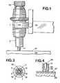
- the device shown comprises an outer body 1, made of plastic, and an inner body 2, metallic, of generally cylindrical shape and axially pierced with a hole 3 which ends in 4 by a conical widening 4, at the place of the end 5 of the body 2.
- a clamp comprising a cylindrical part 6 capable of sliding axially in the hole 3, and a slotted part to form four arms 7 (fig. 3) which, at their free end, have a conical part 8 provided for cooperate, as will be seen below, with the cone 4 of the body 2 ..
- the interior of the split part 7 of the clamp 6,7 forms an axial cylindrical channel 14 into which a cylindrical part 16 of a knife holder 15 can slide.
- a cylindrical part 17 of the knife holder 15 is located at the outside of the body 2, beyond its end 5. The diameter of the part 17 is greater than that of the part 16 and of the channel 14.
- a shoulder 18 provided to abut against the free end of the arms 7 of the clamp 6,7, in order to fix the axial position of the knife holder 15 in the clamp 6,7.
- the knife holder 15 has four longitudinal slots 19, in its region which is close to the free end of the arms 7 of the clamp 6.7 (when the members are in the position shown in FIG. 2, which is the working position of the device).
- the knife holder 15 In its part 16, the knife holder 15 is axially threaded. A micrometric adjustment screw 20 is engaged in this internal thread.
- the knife holder 15 is reintroduced into the pliers 6,7, taking care that the shoulder 18 abuts against the end of the arms 7.
- the button 12 is turned to bring the conical end of the arms 7 of pliers in contact with cone 4, and tightened by turning.
- the arms 7 then flex and act radially on the slotted part of the knife holder 15, which in turn flexes and energetically clamps the part 22 of the knife, which immobilizes the latter in the knife holder 6,7 and the latter by relation to the body 1,2. Simultaneously, the clamp and the body of the device are secured.
- the sheet 27 is detached from its support 29 and the parts of this sheet foreign to cutting, are removed by tearing along the groove. Given the very small diameter of the active part of the tip 25 and the very small thickness of the part to be torn, the result is a clean cut practically equivalent to that obtained with a conventional cutting knife.
- the shape of revolution of the knife-shaped point 25 makes it possible to cut all the possible shapes without difficulty: curves, sharp angles, etc.
Applications Claiming Priority (2)
| Application Number | Priority Date | Filing Date | Title |
|---|---|---|---|
| CH5895/84 | 1984-12-11 | ||
| CH589584A CH659970A5 (fr) | 1984-12-11 | 1984-12-11 | Procede et dispositif pour decouper automatiquement, selon un dessin choisi, une feuille adherant de facon detachable a un support. |
Publications (2)
| Publication Number | Publication Date |
|---|---|
| EP0185617A2 true EP0185617A2 (de) | 1986-06-25 |
| EP0185617A3 EP0185617A3 (de) | 1988-03-16 |
Family
ID=4301141
Family Applications (1)
| Application Number | Title | Priority Date | Filing Date |
|---|---|---|---|
| EP85810586A Withdrawn EP0185617A3 (de) | 1984-12-11 | 1985-12-10 | Verfahren und Vorrichtung zum Schneiden von Blättern nach einer Linie |
Country Status (2)
| Country | Link |
|---|---|
| EP (1) | EP0185617A3 (de) |
| CH (1) | CH659970A5 (de) |
Cited By (2)
| Publication number | Priority date | Publication date | Assignee | Title |
|---|---|---|---|---|
| EP0956930A2 (de) * | 1998-04-17 | 1999-11-17 | Brother Kogyo Kabushiki Kaisha | Vorrichtung zur Einstellung des Abstandes zwischen einem Schneidwekzeug und der Oberfläche eines Bogens |
| DE102020127951A1 (de) | 2020-08-03 | 2022-02-03 | NTS electronic and components GmbH | Schleppmesserhaltevorrichtung |
Families Citing this family (1)
| Publication number | Priority date | Publication date | Assignee | Title |
|---|---|---|---|---|
| DE19508587A1 (de) * | 1995-03-13 | 1996-09-19 | Staedtler Fa J S | Vorrichtung zum Schneiden oder Ritzen, insbesondere für Plotter und/oder für sonstige, vorzugsweise automatische, Schreib-, Zeichen-, Ritz- oder Schneidanlagen oder -geräte |
Citations (9)
| Publication number | Priority date | Publication date | Assignee | Title |
|---|---|---|---|---|
| DE1061237B (de) * | 1954-07-01 | 1959-07-09 | Stommel & Voos Stahlstempelfab | Gravierstichel fuer Kopiermaschinen |
| US3110226A (en) * | 1960-08-01 | 1963-11-12 | Green Instr Company | Depth control device for cutting machine |
| US3339279A (en) * | 1964-07-17 | 1967-09-05 | Robert H Sovar | Hollow engraving point and holder for engraving coated transparent sheets |
| DE1927928A1 (de) * | 1968-06-08 | 1969-12-11 | Philips Nv | Verfahren zum Schneiden eines Musters in einer Kunststoffschicht |
| FR2327871A1 (fr) * | 1975-10-13 | 1977-05-13 | Nec | Tete de gravure |
| EP0036843A1 (de) * | 1980-03-19 | 1981-09-30 | ADVANCED TECHNOLOGY TRADING & CONSULTING S.r.l. | Kopf für Plottermaschinen, fähig zum selektiven Zeichnen und Zuschneiden in Bögen von mittels eines Computers gespeicherten Figuren |
| US4367588A (en) * | 1978-05-24 | 1983-01-11 | Herbert Thomas A | Process for cutting strippable film |
| GB2133731A (en) * | 1982-12-29 | 1984-08-01 | Gerber Garment Technology Inc | Method and apparatus for forming pattern pieces |
| EP0116415A2 (de) * | 1983-01-21 | 1984-08-22 | Protocol Engineering Limited | Herstellung von Trennungslinien an Blättern oder sonstigen Elementen |
-
1984
- 1984-12-11 CH CH589584A patent/CH659970A5/fr not_active IP Right Cessation
-
1985
- 1985-12-10 EP EP85810586A patent/EP0185617A3/de not_active Withdrawn
Patent Citations (9)
| Publication number | Priority date | Publication date | Assignee | Title |
|---|---|---|---|---|
| DE1061237B (de) * | 1954-07-01 | 1959-07-09 | Stommel & Voos Stahlstempelfab | Gravierstichel fuer Kopiermaschinen |
| US3110226A (en) * | 1960-08-01 | 1963-11-12 | Green Instr Company | Depth control device for cutting machine |
| US3339279A (en) * | 1964-07-17 | 1967-09-05 | Robert H Sovar | Hollow engraving point and holder for engraving coated transparent sheets |
| DE1927928A1 (de) * | 1968-06-08 | 1969-12-11 | Philips Nv | Verfahren zum Schneiden eines Musters in einer Kunststoffschicht |
| FR2327871A1 (fr) * | 1975-10-13 | 1977-05-13 | Nec | Tete de gravure |
| US4367588A (en) * | 1978-05-24 | 1983-01-11 | Herbert Thomas A | Process for cutting strippable film |
| EP0036843A1 (de) * | 1980-03-19 | 1981-09-30 | ADVANCED TECHNOLOGY TRADING & CONSULTING S.r.l. | Kopf für Plottermaschinen, fähig zum selektiven Zeichnen und Zuschneiden in Bögen von mittels eines Computers gespeicherten Figuren |
| GB2133731A (en) * | 1982-12-29 | 1984-08-01 | Gerber Garment Technology Inc | Method and apparatus for forming pattern pieces |
| EP0116415A2 (de) * | 1983-01-21 | 1984-08-22 | Protocol Engineering Limited | Herstellung von Trennungslinien an Blättern oder sonstigen Elementen |
Cited By (4)
| Publication number | Priority date | Publication date | Assignee | Title |
|---|---|---|---|---|
| EP0956930A2 (de) * | 1998-04-17 | 1999-11-17 | Brother Kogyo Kabushiki Kaisha | Vorrichtung zur Einstellung des Abstandes zwischen einem Schneidwekzeug und der Oberfläche eines Bogens |
| EP0956930A3 (de) * | 1998-04-17 | 2001-01-17 | Brother Kogyo Kabushiki Kaisha | Vorrichtung zur Einstellung des Abstandes zwischen einem Schneidwekzeug und der Oberfläche eines Bogens |
| US6341548B1 (en) | 1998-04-17 | 2002-01-29 | Brother Kogyo Kabushiki Kaisha | Device for adjusting distance of cutting blade from workpiece sheet |
| DE102020127951A1 (de) | 2020-08-03 | 2022-02-03 | NTS electronic and components GmbH | Schleppmesserhaltevorrichtung |
Also Published As
| Publication number | Publication date |
|---|---|
| EP0185617A3 (de) | 1988-03-16 |
| CH659970A5 (fr) | 1987-03-13 |
Similar Documents
| Publication | Publication Date | Title |
|---|---|---|
| BE1013031A3 (fr) | Methode de preparation de cables coaxiaux avec un conducteur exterieur annele, et outil a cet effet. | |
| WO1991004715A1 (fr) | Prothese femoro-patellaire et ses dispositifs de mise en place | |
| CH632175A5 (fr) | Arbre d'alesoir annulaire. | |
| EP0185617A2 (de) | Verfahren und Vorrichtung zum Schneiden von Blättern nach einer Linie | |
| BE429465A (fr) | Machine à souder par l'électricité | |
| EP0081466A1 (de) | Raspelmaschine für Käse | |
| FR2465543A1 (fr) | Dispositif de reglage micrometrique d'une plaquette de coupe fixee par vis sur un support | |
| CH692244A5 (fr) | Procédé de fixation d'un ressort dans un corps creux. | |
| FR2657035A1 (fr) | Machine pour l'affutage de forets helicouidaux. | |
| FR2660547A1 (fr) | Appareil chirurgical pour realiser une decoupe conique de la cornee. | |
| JPH08163740A (ja) | 電線被覆の皮むき工具 | |
| CH261448A (fr) | Machine à graver. | |
| JPH02124080A (ja) | 果実類の処理装置 | |
| JPS6218343Y2 (de) | ||
| EP1977844B1 (de) | Vorrichtung zum Innenentgraten von Rohren | |
| FR2495033A1 (fr) | Filiere pour dispositif de taillage de filetages | |
| EP0044249A1 (de) | Werkstücktisch mit einer daran befestigten Dekupiersäge | |
| CH95386A (fr) | Machine à tailler les crayons. | |
| BE644696A (de) | ||
| EP0387130A1 (de) | Vorrichtung zum Markieren der kristallinischen Orientierung und Schleifen eines Stabes | |
| CH346789A (fr) | Outillage pour la préparation du logement destiné à recevoir la bille et pour le perçage du canal d'amenée de l'encre à celle-ci dans une pointe de stylo à bille | |
| CH355319A (fr) | Dispositif pour percer des orifices d'aération dans des articles à fumer | |
| FR2772661A1 (fr) | Outil manuel et ensemble de decoupe | |
| JP2001238319A (ja) | 被覆電線の導体口出器 | |
| CH684877A5 (fr) | Instrument pour le traitement des canaux radiculaires dentaires. |
Legal Events
| Date | Code | Title | Description |
|---|---|---|---|
| PUAI | Public reference made under article 153(3) epc to a published international application that has entered the european phase |
Free format text: ORIGINAL CODE: 0009012 |
|
| AK | Designated contracting states |
Kind code of ref document: A2 Designated state(s): CH DE FR GB IT LI |
|
| PUAL | Search report despatched |
Free format text: ORIGINAL CODE: 0009013 |
|
| AK | Designated contracting states |
Kind code of ref document: A3 Designated state(s): CH DE FR GB IT LI |
|
| STAA | Information on the status of an ep patent application or granted ep patent |
Free format text: STATUS: THE APPLICATION IS DEEMED TO BE WITHDRAWN |
|
| 18D | Application deemed to be withdrawn |
Effective date: 19880105 |
|
| RIN1 | Information on inventor provided before grant (corrected) |
Inventor name: HERMANJAT, MARC Inventor name: ZURCHER, JEAN-FRANCOIS |