EP0184745B1 - Toboggan d'évacuation - Google Patents
Toboggan d'évacuation Download PDFInfo
- Publication number
- EP0184745B1 EP0184745B1 EP19850115245 EP85115245A EP0184745B1 EP 0184745 B1 EP0184745 B1 EP 0184745B1 EP 19850115245 EP19850115245 EP 19850115245 EP 85115245 A EP85115245 A EP 85115245A EP 0184745 B1 EP0184745 B1 EP 0184745B1
- Authority
- EP
- European Patent Office
- Prior art keywords
- inflatable
- tubes
- evacuation device
- door
- tube
- Prior art date
- Legal status (The legal status is an assumption and is not a legal conclusion. Google has not performed a legal analysis and makes no representation as to the accuracy of the status listed.)
- Expired
Links
Images


Classifications
-
- B—PERFORMING OPERATIONS; TRANSPORTING
- B64—AIRCRAFT; AVIATION; COSMONAUTICS
- B64D—EQUIPMENT FOR FITTING IN OR TO AIRCRAFT; FLIGHT SUITS; PARACHUTES; ARRANGEMENTS OR MOUNTING OF POWER PLANTS OR PROPULSION TRANSMISSIONS IN AIRCRAFT
- B64D25/00—Emergency apparatus or devices, not otherwise provided for
- B64D25/08—Ejecting or escaping means
- B64D25/14—Inflatable escape chutes
-
- A—HUMAN NECESSITIES
- A62—LIFE-SAVING; FIRE-FIGHTING
- A62B—DEVICES, APPARATUS OR METHODS FOR LIFE-SAVING
- A62B1/00—Devices for lowering persons from buildings or the like
- A62B1/20—Devices for lowering persons from buildings or the like by making use of sliding-ropes, sliding-poles or chutes, e.g. hoses, pipes, sliding-grooves, sliding-sheets
-
- B—PERFORMING OPERATIONS; TRANSPORTING
- B61—RAILWAYS
- B61B—RAILWAY SYSTEMS; EQUIPMENT THEREFOR NOT OTHERWISE PROVIDED FOR
- B61B12/00—Component parts, details or accessories not provided for in groups B61B7/00 - B61B11/00
- B61B12/005—Rescue devices for passengers
Definitions
- This invention relates to an inflatable evacuation slide device and more particularly to an inflatable slide for use on elevated trains where there is a restricted clearance space on either side of the railway car.
- a self-supporting inflatable evacuation device having the features of the precharacterizing part of Claim 1 is known from US-A-3 692 144.
- the known evacuation device is designed for relying upon the wing of an aircraft for deployment as the evacuees walk on a portion of the evacuation device that is supported by the wing of the craft.
- the first portion and the second portion of the evacuation device extend essentially in the same direction, as seen from above.
- EP-A-0 109 610 discloses an inflatable evacuation device that is deployed from an aircraft directly as a single unit in a single direction extending laterally from the craft.
- the present invention is directed to a novel inflatable evacuation device which provides a cantilever type inflatable porch or platform immediately adjacent a side exit or access door of an elevated vehicle such as a train.
- An inflatable evacuation slide for an elevated vehicle such as a train is provided wherein the evacuation device has a platform located immediately adjacent one of the exit doors of the vehicle to facilitate the movement of passengers away from the vehicle.
- the platform is connected to an inflatable slide that lies in the same general direction as the train thus enabling its deployment where there is little clearance space along the path of train's movement.
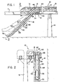
- FIG. 1 a train 10 mounted for movement on one of a pair of laterally spaced rails 11 which in turn are suitably supported by a plurality of longitudinally spaced columns 12 (only one shown).
- the train 10 has a plurality of access doors 13 spaced along its one side to facilitate the loading and unloading.
- a storage means 15 (Figs. 5 and 7) for an inflatable escape slide 16.
- the storage means or compartment 15 is mounted on a depending support 20 that also journals rollers 21 and 22 which are adapted to engage rail 11.
- Storage means 15 has a door 23 suitably hinged which upon opening will extend to a horizontal position and held in place by a cable 24 which interconnects the door 23 to a support bracket within the upper portion of the storage compartment 15.
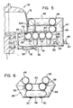
- the door 23 has a planar support member 25 supporting a pair of horizontally extending inflatable tubes 30 and 31 that extend in a direction outwardly or in a direction that is normal to the access or exit doors 13.
- Mounted above and transversely of the pair of tubes 30 and 31 are a plurality of inflatable tubes 35, 36, 37 and 38 (Fig. 5). All of such tubes 35 through 38 are suitably bonded to adjacent tubes preferably along their side portions.
- tubes 35 through 38 are bonded along their lowermost sides to the top of the horizontally extending tubes 30 and 31.
- a panel 40 is fastened tangentially to the inflatable tubes 35 through 38 to provide a platform, porch or walkway from the exit passageway of door 13. Such platform or walkway on panel is maintained in a horizontal position when escape slide is deployed by the inflatable tubes 35 through 38 and tubes 30, 31 as well as by the door 23 which is held in a horizontal plane by the cable 24.
- the inflatable tube 35 extends upwardly on either side of the door 13 designating such upward extensions of the tube 35 as inflatable tubes 35L and 35R ( Figures 3 and 5).
- Tube 35L communicates directly with a horizontally extending tube 41 which in turn communicates directly with a downwardly inclined inflatable tube 42 that communicates in turn with another inclined tube 43 via a short connecting tube 44.
- Tube 35R communicates directly ( Figure 5) with a horizontally extending tube 45 which in turn communicates directly with a horizontally extending tube 46 that is normal to such tube 45.
- tube 46 communicates with a vertically disposed tube 47 which tube 47 in turn communicates directly with tube 30.
- Tube 30 has an aspirator 48 (Figs.
- Aspirator 49 has a conduit 50 connecting it to a regulator and bottle or reservoir assembly 51 of compressed gas.
- Aspirators as is well known in the art utilize air from a compressed gas source and aspirate ambient air to inflate life rafts, escape slide, bag or other inflatables.
- US-A-2,975,958 shows an aspirating nozzle, aspirating tube and closure valve.
- US-A-3,056,540 shows an aspirating passageway and valves.
- US-A-4,368,009 shows another type of aspirator device that is used to inflate escape slides.
- Inflatable tube 46 ( Figures 1 and 3) communicates with inclined tube 53 which in turn communicates with inclined tube 55 via connecting tube 56.
- the inflatable tubes 36 and 38 which form part of the main support for the platform or porch panel 40 communicate directly with a pair of lower inclined inflatable tubes 58 and 59 respectively, which tubes 58 and 59 have a slide panel 60 suitably attached or adhered to their upper surfaces by any suitable means.
- the respective lower inclined inflatable tubes 58 and 59 are connected or attached along their upper outer sides to the upper inclined inflatable tubes 43 and 55 forming an escape slide with protective side constraints or guides.
- inflatable tube 31 is connected via aspirator 62 and conduit 63 to reservoir or bottle 51.
- the compressed air via aspirator 62 inflates the lower set of tubes such as tubes 31, 36, 37, 38 and tube 65, which in turn communicates directly with inclined tube 59 (as seen in Figure 1).
- Inclined tube 59 is suitably adhered along its upper surface to the lower surface of upper inclined tube 55 ( Figures 1 and 6) to help insure deployment of the escape slide.
- a truss bag 68 for side lateral support is also provided midway along the escape slide, transverse to the longitudinal line of the inclined inflatable tubes 43, 55, 58 and 59. As seen in Figure 1 and 6, such truss bag 68 encompasses the escape slide along the bottom and both side portions, communicating with the two upper inflatable tubes 43 and 55. Mounted closely adjacent to the lower cross portion of truss bag 68 is a truss tube 69 fastened to the undersides of the two lower tubes 58 and 59 which is at a position approximately one-half the length of the escape slide. Such truss tube 69 communicates via suitable ports to tubes 58 and 59 and accordingly is inflated simultaneously with such tubes.
- the truss will function to provide tension to the escape slide with either inflatable truss bag 68 or truss tube 69 deflated and either tube 69 or bag 68 will have approximately the same bending resistance.
- the inflatable tubes as deployed are adhesively bonded to each other so that upon inflation will form a rigid supporting porch, or platform and escape slide.
- the inflatable tubes are preferably fabricated from a neoprene rubber coated nylon fabric.
- the panel 40 which serves as a walkway for the porch is preferably coated with a non-slip rubber coating to improve the passenger's footing on such walkway.
- Such panel 40 may be attached to the foot of the exit door by any number of well known means, however as shown in Figure 5 an exterior flap 71 is suitably attached to a bar 73 located inside the train body thereby supporting the exit door end of the panel or walkway 40.
- the slide as shown in Fig. 7 is disposed and folded within the storage means 15 having the swinging door 23 forming part of such compartment confining means.
- compressed air from the bottle 51 will inflate via aspirators 49 and 62 their respective sets of tubes.
- Aspirator 62 is connected to inflatable tube 31 and will inflate such tube immediately.
- Tubes 36 and 38 which are connected to tube 31 will also inflate as will tube 37, 65, 58, 61, 69 and 59 which are the lower set of inflatable tubes.
- Aspirator 49 is connected to inflatable tube 30 and will inflate such tube immediately.
- Tubes 47 (Fig. 4), 46, 45, 35, 41, 42, 43, 53, 68, and 55 are all connected to such tube 30 and will also inflate with such tube, which tubes are considered the upper inflatable set of tubes.
- first or second set of tubes inflated, egress can be assured.
- the passengers in the train can exit to the platform and then use the deployed escape slide which is disposed in the general direction of the train to assure full deployment of the escape slide under conditions where clearance space to either side of the train ordinarily would present problems of escape slide deployment.
Claims (6)
Applications Claiming Priority (2)
| Application Number | Priority Date | Filing Date | Title |
|---|---|---|---|
| US67762884A | 1984-12-03 | 1984-12-03 | |
| US677628 | 1984-12-03 |
Publications (3)
| Publication Number | Publication Date |
|---|---|
| EP0184745A2 EP0184745A2 (fr) | 1986-06-18 |
| EP0184745A3 EP0184745A3 (en) | 1987-10-14 |
| EP0184745B1 true EP0184745B1 (fr) | 1990-12-12 |
Family
ID=24719494
Family Applications (1)
| Application Number | Title | Priority Date | Filing Date |
|---|---|---|---|
| EP19850115245 Expired EP0184745B1 (fr) | 1984-12-03 | 1985-11-30 | Toboggan d'évacuation |
Country Status (5)
| Country | Link |
|---|---|
| EP (1) | EP0184745B1 (fr) |
| JP (1) | JPS61135857A (fr) |
| AU (1) | AU586652B2 (fr) |
| CA (1) | CA1264684A (fr) |
| DE (1) | DE3580904D1 (fr) |
Cited By (1)
| Publication number | Priority date | Publication date | Assignee | Title |
|---|---|---|---|---|
| WO2014078586A1 (fr) * | 2012-11-14 | 2014-05-22 | Swift Tram, Inc. | Système de transport à voitures suspendues |
Families Citing this family (10)
| Publication number | Priority date | Publication date | Assignee | Title |
|---|---|---|---|---|
| US6581334B2 (en) * | 2001-11-02 | 2003-06-24 | Goodrich Corporation | High strength T-joint for inflatable tube structures |
| GB2420105A (en) * | 2004-11-15 | 2006-05-17 | Bombardier Transp Gmbh | Inflatable escape chute for a train |
| JP5237930B2 (ja) * | 2009-12-25 | 2013-07-17 | 株式会社日立製作所 | 軌条車両に備えられる避難装置及びその避難装置の軌条車両への固定方法 |
| JP5793124B2 (ja) * | 2012-08-03 | 2015-10-14 | 株式会社日立製作所 | 軌条車両に備えられる避難装置 |
| AT518367B1 (de) * | 2016-03-03 | 2018-02-15 | Siemens Ag Oesterreich | Evakuierungseinrichtung |
| US10351251B2 (en) * | 2016-12-20 | 2019-07-16 | Goodrich Corporation | Audio evacuation system readiness indicator |
| CN108583586B (zh) * | 2018-05-28 | 2024-01-19 | 中建空列(北京)科技有限公司 | 用于空铁系统的逃生装置及空铁系统 |
| CN108482392B (zh) * | 2018-05-28 | 2024-02-13 | 中建空列(北京)科技有限公司 | 用于空铁系统的逃生装置及空铁系统 |
| JP7385862B2 (ja) * | 2019-10-01 | 2023-11-24 | 芦森工業株式会社 | 避難用シュート |
| CN115610450A (zh) * | 2022-10-28 | 2023-01-17 | 中铁四院集团新型轨道交通设计研究有限公司 | 一种悬挂式单轨移动疏散系统 |
Family Cites Families (4)
| Publication number | Priority date | Publication date | Assignee | Title |
|---|---|---|---|---|
| US3692144A (en) * | 1970-11-18 | 1972-09-19 | Garrett Corp | Fluid distensible truss |
| US4013247A (en) * | 1975-12-30 | 1977-03-22 | The Boeing Company | Mechanical support apparatus for the stabilization of an inflatable escape slide |
| US4018321A (en) * | 1976-05-21 | 1977-04-19 | The B. F. Goodrich Company | Escape slide and platform assembly |
| US4434870A (en) * | 1982-11-22 | 1984-03-06 | The B. F. Goodrich Company | Evacuation slide device |
-
1985
- 1985-11-26 AU AU50372/85A patent/AU586652B2/en not_active Ceased
- 1985-11-30 DE DE8585115245T patent/DE3580904D1/de not_active Expired - Fee Related
- 1985-11-30 EP EP19850115245 patent/EP0184745B1/fr not_active Expired
- 1985-12-02 JP JP26954185A patent/JPS61135857A/ja active Pending
- 1985-12-02 CA CA000496684A patent/CA1264684A/fr not_active Expired - Fee Related
Cited By (1)
| Publication number | Priority date | Publication date | Assignee | Title |
|---|---|---|---|---|
| WO2014078586A1 (fr) * | 2012-11-14 | 2014-05-22 | Swift Tram, Inc. | Système de transport à voitures suspendues |
Also Published As
| Publication number | Publication date |
|---|---|
| AU586652B2 (en) | 1989-07-20 |
| CA1264684A (fr) | 1990-01-23 |
| DE3580904D1 (de) | 1991-01-24 |
| AU5037285A (en) | 1986-06-12 |
| EP0184745A2 (fr) | 1986-06-18 |
| JPS61135857A (ja) | 1986-06-23 |
| EP0184745A3 (en) | 1987-10-14 |
Similar Documents
| Publication | Publication Date | Title |
|---|---|---|
| US4723628A (en) | Evacuation slide | |
| US4018321A (en) | Escape slide and platform assembly | |
| EP0184745B1 (fr) | Toboggan d'évacuation | |
| US5360186A (en) | Inflatable slide raft assembly | |
| EP0893343B1 (fr) | Ensemble de toboggan d'évacuation gonflable | |
| EP0109610B1 (fr) | Glissière pour l'évacuation en cas d'urgence | |
| CA1138796A (fr) | Glissiere d'evacuation | |
| US4375877A (en) | Escape slide stowage and deployment system | |
| US3833088A (en) | Slide-raft for emergency aircraft evacuation | |
| US6769647B2 (en) | Automatic inflation system for evacuation slide | |
| US3860984A (en) | Inflatable life raft escape slide | |
| US5975467A (en) | Inflatable evacuation slide | |
| US4846422A (en) | Single piece evacuation system for aircraft or the like | |
| US3102623A (en) | Escape slide | |
| US6536715B1 (en) | Inflatable evacuation slide with arch support | |
| US3827094A (en) | Inflatable life raft escape slide | |
| US3973645A (en) | Inflatable evacuation slide | |
| EP0864493B1 (fr) | Glissière de secours avec un agencement à tube de support | |
| US3692144A (en) | Fluid distensible truss | |
| US3476338A (en) | Inflatable ramp | |
| GB2131369A (en) | Marine escape system | |
| EP1302400B1 (fr) | Toboggan d'évacuation avec un élément de support au centre du pied en bas | |
| US4684079A (en) | Inflatable evacuation device | |
| EP1441950B1 (fr) | Glissiere d'evacuation comportant un tube de support transversal dans sa partie inferieure | |
| WO1996015024A1 (fr) | Procede et dispositif d'arrimage respectivement des ponts fermes et du chargement a bord de navires |
Legal Events
| Date | Code | Title | Description |
|---|---|---|---|
| PUAI | Public reference made under article 153(3) epc to a published international application that has entered the european phase |
Free format text: ORIGINAL CODE: 0009012 |
|
| AK | Designated contracting states |
Kind code of ref document: A2 Designated state(s): DE FR GB |
|
| PUAL | Search report despatched |
Free format text: ORIGINAL CODE: 0009013 |
|
| AK | Designated contracting states |
Kind code of ref document: A3 Designated state(s): DE FR GB |
|
| 17P | Request for examination filed |
Effective date: 19880407 |
|
| 17Q | First examination report despatched |
Effective date: 19881223 |
|
| GRAA | (expected) grant |
Free format text: ORIGINAL CODE: 0009210 |
|
| AK | Designated contracting states |
Kind code of ref document: B1 Designated state(s): DE FR GB |
|
| ET | Fr: translation filed | ||
| REF | Corresponds to: |
Ref document number: 3580904 Country of ref document: DE Date of ref document: 19910124 |
|
| PLBE | No opposition filed within time limit |
Free format text: ORIGINAL CODE: 0009261 |
|
| STAA | Information on the status of an ep patent application or granted ep patent |
Free format text: STATUS: NO OPPOSITION FILED WITHIN TIME LIMIT |
|
| 26N | No opposition filed | ||
| PGFP | Annual fee paid to national office [announced via postgrant information from national office to epo] |
Ref country code: FR Payment date: 19940930 Year of fee payment: 10 |
|
| PGFP | Annual fee paid to national office [announced via postgrant information from national office to epo] |
Ref country code: GB Payment date: 19941003 Year of fee payment: 10 |
|
| PGFP | Annual fee paid to national office [announced via postgrant information from national office to epo] |
Ref country code: DE Payment date: 19941005 Year of fee payment: 10 |
|
| PG25 | Lapsed in a contracting state [announced via postgrant information from national office to epo] |
Ref country code: GB Effective date: 19951130 |
|
| GBPC | Gb: european patent ceased through non-payment of renewal fee |
Effective date: 19951130 |
|
| PG25 | Lapsed in a contracting state [announced via postgrant information from national office to epo] |
Ref country code: FR Effective date: 19960731 |
|
| PG25 | Lapsed in a contracting state [announced via postgrant information from national office to epo] |
Ref country code: DE Effective date: 19960801 |
|
| REG | Reference to a national code |
Ref country code: FR Ref legal event code: ST |