EP0184570A2 - Verfahren und Vorrichtung zur Herstellung eines Betonpfahles oder ähnlichem im Boden durch Verwendung eines biegsamen Rohres, geschützt durch eine Schutzvorrichtung, vorzugsweise eine Hülse - Google Patents
Verfahren und Vorrichtung zur Herstellung eines Betonpfahles oder ähnlichem im Boden durch Verwendung eines biegsamen Rohres, geschützt durch eine Schutzvorrichtung, vorzugsweise eine Hülse Download PDFInfo
- Publication number
- EP0184570A2 EP0184570A2 EP85870162A EP85870162A EP0184570A2 EP 0184570 A2 EP0184570 A2 EP 0184570A2 EP 85870162 A EP85870162 A EP 85870162A EP 85870162 A EP85870162 A EP 85870162A EP 0184570 A2 EP0184570 A2 EP 0184570A2
- Authority
- EP
- European Patent Office
- Prior art keywords
- tube
- flexible
- spindle
- concrete
- pipe
- Prior art date
- Legal status (The legal status is an assumption and is not a legal conclusion. Google has not performed a legal analysis and makes no representation as to the accuracy of the status listed.)
- Withdrawn
Links
Images

Classifications
-
- E—FIXED CONSTRUCTIONS
- E02—HYDRAULIC ENGINEERING; FOUNDATIONS; SOIL SHIFTING
- E02D—FOUNDATIONS; EXCAVATIONS; EMBANKMENTS; UNDERGROUND OR UNDERWATER STRUCTURES
- E02D5/00—Bulkheads, piles, or other structural elements specially adapted to foundation engineering
- E02D5/22—Piles
- E02D5/34—Concrete or concrete-like piles cast in position ; Apparatus for making same
- E02D5/38—Concrete or concrete-like piles cast in position ; Apparatus for making same making by use of mould-pipes or other moulds
- E02D5/385—Concrete or concrete-like piles cast in position ; Apparatus for making same making by use of mould-pipes or other moulds with removal of the outer mould-pipes
Definitions
- the present invention essentially relates to a method and device for producing a pile, for example of concrete or similar material, in the ground using a hose made of flexible material protected by a protective device, preferably in the form of a time zone.
- the plastic pipe is rigidly stretched in a driving tube between the driving head and a support device located above said pipe.
- the plastic pipe After the jacking pipe, for example, has reached the required depth, the plastic pipe is filled with concrete in a pourable form. Concrete applies the plastic pipe to the inside wall of the jacking pipe.
- the plastic pipe When the jacking pipe is removed, the plastic pipe may be damaged by irregularities. tears in the wall of this tube.
- the present invention therefore aims to solve the new technical problem consisting in providing a method and a device for producing a pile, for example of concrete or similar material, in the ground, using a material pipe. plastic, so as to protect it effectively during driving and removal of the driving tube, in a relatively simple and inexpensive manner.
- the present invention solves this technical problem for the first time.
- the flexible pipe is stored on a cassette arranged inside the spindle.
- This flexible pipe can be arranged in the form of an accordion on said cassette.
- the plastic pipe being placed in the spindle during driving and during the first phase of withdrawal of the driving pipe can in no way be damaged.
- the plastic pipe is pulled, over an extra thickness dimensioned so that the pipe is rigidly stretched, without undergoing excessive stress.
- the flexible pipe separates from the spindle and is filled simultaneously, for example with fluid or liquid concrete or the like.
- This separation has the effect that the lower end of the jacking tube is slightly above the lower end of the spindle, so that the plastic pipe is not applied against the inner bottom edge of the jacking tube under the effect of concrete pressure.
- the plastic pipe is no longer pressed against the inner face of the driving tube, generally made of steel, over its entire height under the effect of the pressure of the concrete.
- This plastic pipe can be arranged over the entire length of the pile, for example, or only over part of it.
- the lower end of the plastic pipe is fixed to the driving head or the like by means of wires, cables or any other similar device.
- the plastic pipe tick is not present on the lower part of the pile, for example, so that liquid or fluid concrete can flow freely until contact with the surrounding soil, which allows a good bond between the concrete and the soil and thus avoid any harmful repercussions on the bearing capacity of the piles.
- the plastic pipe can also be arranged along the entire length of the pile.
- the present invention also relates to a device for producing a pile, for example of concrete or similar material, in the ground, comprising a sinking tube made of resistant material, relatively rigid or non-deformable, said sinking tube comprising inside a hose made of flexible, flexible material, for example plastic, intended to serve as a casing for concrete or the like to define the pile, rigidly stretched between the driving head and a support device, characterized in that the support device includes a protection device suspended inside the jacking tube protecting the flexible hose against contact with the jacking tube.
- the protection device comprises a spindle with double concentric walls radially spaced providing a space for the arrangement of the flexible pipe.
- the flexible hose is wound on a cassette arranged inside the spindle.
- the plastic pipe can be arranged over the entire length of the pile, for example, or only over part of it.
- the plastic pipe is not present on the lower part of the pile, for example, so that the fluid or liquid concrete or similar material can flow freely until contact with the surrounding soil, which makes it possible to obtain a good bond between the concrete and the ground and thus to avoid any harmful repercussion on the bearing power of the piles.
- the plastic pipe can also be arranged over the entire length of the pile.
- annular rubber flap is provided on the underside of the spindle.
- the length and arrangement of this bib can be adapted to the particular circumstances.
- this flap may even be totally lacking.
- this flap can be short and not very flexible and constitute, in this case, only a seal against screw concrete when the jacking pipe is filled with concrete. Under the effect of the concrete pressure, this flap is applied against the wall of the driving tube, at the time of the start of concrete pouring and therefore automatically ensures a good seal.
- the rubber flap can be longer, so that its underside has the possibility of expanding so that the rubber flap takes the shaped like a truncated cone.
- the rubber flap must have the characteristic that its lower face can reach a markedly greater diameter, while its upper face remains at the same diameter.
- the flap is preferably made for this purpose in strips of a pleated envelope, or in an expandable material.
- the flap Under the effect of pressure, for example liquid concrete flowing in the pipe or the sinking tube, the flap is pressed outwards when the concrete escapes from the interior of the spindle and is forced to take the shape of a truncated cone.
- the plastic pipe is separated from the spindle when the spindle is extracted plus the driving tube and over the flap expanded by the pressure of the concrete.
- the dimensions of the flap and the plastic pipe must be chosen so that the plastic pipe is slightly under tension when the spindle is extracted.
- the arrangement of the flexible plastic pipe, or plastic material, on a cassette is not necessary but is only an auxiliary means to speed up production.
- the plastic pipe is placed beforehand on the cassette and the cassette comprising the flexible pipe is introduced into the spindle between the two concentric radially spaced walls. Then, at the lower part of the barrel, there is a detachable ring, generally made of steel, by means of quick coupling means. Finally, the wires or cables connected to the lower end of the flexible pipe are fixed to the driving head.
- the spindle principle can also be applied in cases where the spindle is placed in the driving tube after the latter has been brought to the required depth at which it is sufficient for the lower end of the pipe to be flexible material is retained when extracting the spindle in a different manner than that described above.
- the spindle is generally designed so that the hose made of soft, flexible material, such as plastic, is optimally protected at all stages of operation, by means of a wall forming a hose. or buffer, preferably made of steel, disposed between the hose made of flexible flexible material and the inner wall of the driving tube.
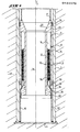
- a device according to the invention for producing the pile for example made of concrete or the like, in the ground, comprises a driving tube 1 made of resistant material, relatively rigid or non-deformable.
- This driving tube 1 includes inside a hose 2 made of flexible, flexible material, for example plastic, intended to serve as a concrete casing or the like to define the pile.
- This pipe 2 is rigidly tensioned between the driving head (not shown in FIG. 1 but clearly visible in FIGS. 2 to 2c), represented by the general reference number 4 and a support device represented by the general reference number 6.
- this device is characterized in that the support device comprises a protection device represented by the general reference number 8 suspended inside the driving tube using suspension cables 9 connected for example to a classic winch.
- This protection device 8 is designed so as to protect the flexible pipe against contact with the internal wall of the driving tube 1.
- the protection device 8 comprises a spindle 10 with double walls 12, 14, respectively internal and external radially spaced, providing a space 16 for the arrangement of the flexible pipe 2.
- the flexible pipe 2 is stored on a cassette 18 disposed inside the spindle 10, that is to say in the space 16 defined between the concentric walls 12, 14.
- the concentric walls 12, 14 are fixed at the upper part of the spindle 10 to a ring 20 of mechanically resistant material, relatively rigid or non-deformable, for example steel.
- This ring has a conical profile 22, the large base of which receives the walls 12, 14.
- the external wall 20 of this ring is provided with sealing means 24 sealing between the ring 20 and the driving tube 1.
- another ring 26 detachable mounted by means of quick coupling to the internal wall 12.
- This ring 26 has on its outer face a conical profile 28 radially increasing in the direction of the driving head 4
- a flap 30, is attached to this ring 26 a flap 30, generally made of rubber.
- This flap 30 is preferably made in the form of strips of a pleated envelope, or else in an expandable material. This flap can for example be made of rubber, natural or synthetic.
- the outer wall 14 is shorter and provides an opening normally closed by an elastic annular closure means 36 such as a flap which can be made of rubber.
- the dimension of the flap 30 varies according to whether the diameter of the flexible flexible pipe 2 differs little or strongly from the inside diameter of the driving tube 1.
- the flap 30 is short and not very flexible, and in this case simply provides only a seal against the concrete when the tube 1 is filled with concrete.
- the flap 30 can be longer so that its underside has the possibility of expanding so that this flap takes the form of a truncated cone.
- the flexible material pipe is fixed at its lower end to the driving head 4 by means of cables or wires 32.
- the spindle 10 has a through axial opening 34 which will allow the free passage of fluid or liquid concrete or any similar material in the direction of the driving head.
- FIG. 2a represents the position of the driving tube 1 and the spindle 10 at the end of the driving step when the driving tube reaches a determined depth.
- the inside of the driving tube 1, therefore of the spindle 10, is filled with fluid or liquid concrete 42 or any other similar material, up to the driving head 4.
- the driving tube 1 is raised slightly while the spindle 10 remains at the same depth.
- the driving tube 1 therefore slides along the spindle 10 and the concrete flows through the spindle during this extraction operation up to the head 4 remaining in place.
- the driving tube 1 is raised enough so that the lower end of the latter is slightly above the lower end of the spindle 10, that is to say in practice above the lower end of the outer wall 14 of the spindle 10 so as not to hinder the passage of the flexible pipe 2, as clearly visible in FIG. 2a.
- FIG. 2b represents an intermediate position showing the spindle partially raised to an intermediate depth.
- the flexible pipe 2 is thus extracted from the spindle 10 because the lower end of the flexible pipe 2 is fixed to the driving head 4 which remains in place, by means of cables or wires 32.
- the flexible pipe ⁇ 2 Since the flexible pipe ⁇ 2 is pulled by being guided by the conical surface 28 of the ring 26 and also by the swelling of the expandable flap 30 under the effect of the pressure of the concrete, this flexible pipe 2 is rigidly stretched, without be overloaded. Furthermore, during the extraction of the driving tube and the spindle 10, the flexible pipe 2 not only separates from the spindle but also simultaneously fills with fluid or liquid concrete or any similar material.
- the flexible pipe 2 is not applied against the inner lower edge of the tube jacking 1 under the effect of concrete pressure and does not risk being damaged.
- the flexible pipe 2 is no longer pressed against the inner face of the driving tube 1 over its entire height under the effect of the pressure of the concrete.
- the flexible pipe 2 can be arranged over the entire length of the pile, for example, or only over part of it.
- the flexible pipe 2 is not present on the lower part of the pile, for example, so that the liquid concrete can flow freely until contact with the surrounding soil, thus making it possible to obtain a good attachment between the concrete 42 and the soil 40 and also avoiding any harmful repercussions on the bearing power of the piles.
- the flexible pipe 2 can also be arranged over the entire length of the pile.
- the sealing devices 24, 38 which are preferably arranged in several places between the spindle 10 and the inner face of the driving tube 1, it is prevented that grains of gravel, for example, do not enter this cavity and that the spindle 10 does not block in the driving tube 1.
- the flexible pipe 2 makes it possible to protect the concrete against the aggressive agents of the soil and avoids an overconsumption of the concrete in soft soils by preventing the formation of huge balls or blisters.
Landscapes
- Engineering & Computer Science (AREA)
- Structural Engineering (AREA)
- Life Sciences & Earth Sciences (AREA)
- General Life Sciences & Earth Sciences (AREA)
- Mining & Mineral Resources (AREA)
- Paleontology (AREA)
- Civil Engineering (AREA)
- General Engineering & Computer Science (AREA)
- Piles And Underground Anchors (AREA)
Applications Claiming Priority (2)
| Application Number | Priority Date | Filing Date | Title |
|---|---|---|---|
| BE214081 | 1984-11-29 | ||
| BE0/214081A BE901163A (fr) | 1984-11-29 | 1984-11-29 | Procede et dispositif de realisation d'un pieu, par exemple en beton ou materiau analogue, dans le sol avec utilisation d'un tuyau en matiere flexible protege par un dispositif de protection de preference sous forme d'un fuseau. |
Publications (2)
| Publication Number | Publication Date |
|---|---|
| EP0184570A2 true EP0184570A2 (de) | 1986-06-11 |
| EP0184570A3 EP0184570A3 (de) | 1986-12-10 |
Family
ID=3843824
Family Applications (1)
| Application Number | Title | Priority Date | Filing Date |
|---|---|---|---|
| EP85870162A Withdrawn EP0184570A3 (de) | 1984-11-29 | 1985-11-21 | Verfahren und Vorrichtung zur Herstellung eines Betonpfahles oder ähnlichem im Boden durch Verwendung eines biegsamen Rohres, geschützt durch eine Schutzvorrichtung, vorzugsweise eine Hülse |
Country Status (1)
| Country | Link |
|---|---|
| EP (1) | EP0184570A3 (de) |
Cited By (2)
| Publication number | Priority date | Publication date | Assignee | Title |
|---|---|---|---|---|
| CN116356807A (zh) * | 2023-04-03 | 2023-06-30 | 深圳市工勘岩土集团有限公司 | 大直径易塌深孔三层钢护筒减阻沉入与精准定位施工方法 |
| CN120401478A (zh) * | 2025-06-30 | 2025-08-01 | 杭州江润科技有限公司 | 大直径双层钢护筒的施工方法 |
Family Cites Families (3)
| Publication number | Priority date | Publication date | Assignee | Title |
|---|---|---|---|---|
| FR2116988A5 (de) * | 1970-12-11 | 1972-07-21 | Labrue Jean Marie | |
| FR2318275A1 (fr) * | 1975-07-17 | 1977-02-11 | Labrue Jean Marie | Procede de realisation de pieux moules dans le sol et tariere creuse pour la mise en oeuvre du procede |
| NL7908738A (nl) * | 1979-12-03 | 1981-07-01 | Stevin Volker Beton Water | Schroefboorpaal met verloren casing. |
-
1985
- 1985-11-21 EP EP85870162A patent/EP0184570A3/de not_active Withdrawn
Cited By (2)
| Publication number | Priority date | Publication date | Assignee | Title |
|---|---|---|---|---|
| CN116356807A (zh) * | 2023-04-03 | 2023-06-30 | 深圳市工勘岩土集团有限公司 | 大直径易塌深孔三层钢护筒减阻沉入与精准定位施工方法 |
| CN120401478A (zh) * | 2025-06-30 | 2025-08-01 | 杭州江润科技有限公司 | 大直径双层钢护筒的施工方法 |
Also Published As
| Publication number | Publication date |
|---|---|
| EP0184570A3 (de) | 1986-12-10 |
Similar Documents
| Publication | Publication Date | Title |
|---|---|---|
| EP0020232B1 (de) | Verfahren und Vorrichtung zur Befestigung von Leitungen, wie Pipelines, auf dem Meeresboden | |
| EP0536256B1 (de) | Radial verformbares rohr mit mehreren lösbar verbundenen elementen | |
| FR2763635A1 (fr) | Appareil et procede pour assurer un support a un cable elec- trique s'etendant dans un tube pour puits, notamment pour transmettre de la puissance a une pompe submersible | |
| EP0402247B1 (de) | Verfahren und Vorrichtung zum Ablösen einer am Beton haftenden Dichtung eines im Boden gegossenen Wandabschnittes | |
| CA2064429C (fr) | Dispositif d'etancheite pour joints d'expansion coupes dans les barrages | |
| EP0184570A2 (de) | Verfahren und Vorrichtung zur Herstellung eines Betonpfahles oder ähnlichem im Boden durch Verwendung eines biegsamen Rohres, geschützt durch eine Schutzvorrichtung, vorzugsweise eine Hülse | |
| FR2534624A1 (fr) | Procede et dispositif pour le decoupage pyrotechnique d'un tube immerge | |
| BE901163A (fr) | Procede et dispositif de realisation d'un pieu, par exemple en beton ou materiau analogue, dans le sol avec utilisation d'un tuyau en matiere flexible protege par un dispositif de protection de preference sous forme d'un fuseau. | |
| CH646881A5 (fr) | Rotor de centrifugeuse avec des cavites a orientation fixe. | |
| LU85071A1 (fr) | Procede et appareil en vue de realiser des pieux betonnes in situ et ayant des bases elargies | |
| EP0167610B1 (de) | Vielfaches piezometer und anwendung eines derartigen piezometers | |
| CA1278925C (fr) | Procede et dispositif de soutenement provisoire des parois d'une tranchee | |
| FR2459356A1 (fr) | Dispositif de forage pour un forage etage | |
| FR2662207A1 (fr) | Dispositif de tubage d'un forage et procede de tubage en resultant. | |
| EP0441076A1 (de) | Rohrförmiger Metallpfahl mit Vorrichtung zur Schlämmeeinpressung im Bereich der Rohrwand | |
| EP0288644A1 (de) | Verfahren und Vorrichtung zum provisorischen Abstützen von Grabenwänden | |
| EP1407085B1 (de) | Verfahren und vorrichtung zur herstellung einer stahlbetonwand im boden | |
| FR2597187A1 (fr) | Procede et dispositif de soutenement provisoire des parois d'une tranchee | |
| FR3055919A1 (fr) | Dispositif de forage de sol pour la realisation d'essais d'expansion en forage d'un sol in situ | |
| FR2522062A1 (fr) | Dispositif de retenue d'une charge de scellement dans un trou d'ancrage prealablement a l'enfoncement d'une tige d'ancrage dans ledit trou | |
| BE1010367A3 (fr) | Tube de carottier, procede de fabrication et utilisation dudit tube interieur. | |
| BE1004846A6 (fr) | Procede pour colmater une fuite de fluide sous pression, en particulier de petrole ou de gaz, et equipement pour la mise en oeuvre de ce procede. | |
| BE898026A (fr) | Installation de pieux. | |
| BE642922A (de) | ||
| BE531656A (de) |
Legal Events
| Date | Code | Title | Description |
|---|---|---|---|
| PUAI | Public reference made under article 153(3) epc to a published international application that has entered the european phase |
Free format text: ORIGINAL CODE: 0009012 |
|
| AK | Designated contracting states |
Kind code of ref document: A2 Designated state(s): CH DE GB LI NL |
|
| PUAL | Search report despatched |
Free format text: ORIGINAL CODE: 0009013 |
|
| AK | Designated contracting states |
Kind code of ref document: A3 Designated state(s): CH DE GB LI NL |
|
| 17P | Request for examination filed |
Effective date: 19870601 |
|
| 17Q | First examination report despatched |
Effective date: 19881209 |
|
| STAA | Information on the status of an ep patent application or granted ep patent |
Free format text: STATUS: THE APPLICATION IS DEEMED TO BE WITHDRAWN |
|
| 18D | Application deemed to be withdrawn |
Effective date: 19890420 |
|
| RIN1 | Information on inventor provided before grant (corrected) |
Inventor name: DE KORT, PETRUS JOHANNES C.M. |