EP0183662A1 - Verfahren zum Anbringen eines elastischen Elementes an eine Kunststoffbahn mittels Klebstoffs - Google Patents
Verfahren zum Anbringen eines elastischen Elementes an eine Kunststoffbahn mittels Klebstoffs Download PDFInfo
- Publication number
- EP0183662A1 EP0183662A1 EP85850323A EP85850323A EP0183662A1 EP 0183662 A1 EP0183662 A1 EP 0183662A1 EP 85850323 A EP85850323 A EP 85850323A EP 85850323 A EP85850323 A EP 85850323A EP 0183662 A1 EP0183662 A1 EP 0183662A1
- Authority
- EP
- European Patent Office
- Prior art keywords
- ribbon
- drum
- suction
- openings
- given path
- Prior art date
- Legal status (The legal status is an assumption and is not a legal conclusion. Google has not performed a legal analysis and makes no representation as to the accuracy of the status listed.)
- Granted
Links
Images


Classifications
-
- A—HUMAN NECESSITIES
- A61—MEDICAL OR VETERINARY SCIENCE; HYGIENE
- A61F—FILTERS IMPLANTABLE INTO BLOOD VESSELS; PROSTHESES; DEVICES PROVIDING PATENCY TO, OR PREVENTING COLLAPSING OF, TUBULAR STRUCTURES OF THE BODY, e.g. STENTS; ORTHOPAEDIC, NURSING OR CONTRACEPTIVE DEVICES; FOMENTATION; TREATMENT OR PROTECTION OF EYES OR EARS; BANDAGES, DRESSINGS OR ABSORBENT PADS; FIRST-AID KITS
- A61F13/00—Bandages or dressings; Absorbent pads
- A61F13/15—Absorbent pads, e.g. sanitary towels, swabs or tampons for external or internal application to the body; Supporting or fastening means therefor; Tampon applicators
- A61F13/15577—Apparatus or processes for manufacturing
- A61F13/15585—Apparatus or processes for manufacturing of babies' napkins, e.g. diapers
- A61F13/15593—Apparatus or processes for manufacturing of babies' napkins, e.g. diapers having elastic ribbons fixed thereto; Devices for applying the ribbons
- A61F13/15609—Apparatus or processes for manufacturing of babies' napkins, e.g. diapers having elastic ribbons fixed thereto; Devices for applying the ribbons the ribbons being applied in an irregular path
-
- B—PERFORMING OPERATIONS; TRANSPORTING
- B29—WORKING OF PLASTICS; WORKING OF SUBSTANCES IN A PLASTIC STATE IN GENERAL
- B29C—SHAPING OR JOINING OF PLASTICS; SHAPING OF MATERIAL IN A PLASTIC STATE, NOT OTHERWISE PROVIDED FOR; AFTER-TREATMENT OF THE SHAPED PRODUCTS, e.g. REPAIRING
- B29C65/00—Joining or sealing of preformed parts, e.g. welding of plastics materials; Apparatus therefor
- B29C65/48—Joining or sealing of preformed parts, e.g. welding of plastics materials; Apparatus therefor using adhesives, i.e. using supplementary joining material; solvent bonding
-
- B—PERFORMING OPERATIONS; TRANSPORTING
- B29—WORKING OF PLASTICS; WORKING OF SUBSTANCES IN A PLASTIC STATE IN GENERAL
- B29C—SHAPING OR JOINING OF PLASTICS; SHAPING OF MATERIAL IN A PLASTIC STATE, NOT OTHERWISE PROVIDED FOR; AFTER-TREATMENT OF THE SHAPED PRODUCTS, e.g. REPAIRING
- B29C65/00—Joining or sealing of preformed parts, e.g. welding of plastics materials; Apparatus therefor
- B29C65/78—Means for handling the parts to be joined, e.g. for making containers or hollow articles, e.g. means for handling sheets, plates, web-like materials, tubular articles, hollow articles or elements to be joined therewith; Means for discharging the joined articles from the joining apparatus
- B29C65/7841—Holding or clamping means for handling purposes
- B29C65/7847—Holding or clamping means for handling purposes using vacuum to hold at least one of the parts to be joined
-
- B—PERFORMING OPERATIONS; TRANSPORTING
- B29—WORKING OF PLASTICS; WORKING OF SUBSTANCES IN A PLASTIC STATE IN GENERAL
- B29C—SHAPING OR JOINING OF PLASTICS; SHAPING OF MATERIAL IN A PLASTIC STATE, NOT OTHERWISE PROVIDED FOR; AFTER-TREATMENT OF THE SHAPED PRODUCTS, e.g. REPAIRING
- B29C65/00—Joining or sealing of preformed parts, e.g. welding of plastics materials; Apparatus therefor
- B29C65/78—Means for handling the parts to be joined, e.g. for making containers or hollow articles, e.g. means for handling sheets, plates, web-like materials, tubular articles, hollow articles or elements to be joined therewith; Means for discharging the joined articles from the joining apparatus
- B29C65/7858—Means for handling the parts to be joined, e.g. for making containers or hollow articles, e.g. means for handling sheets, plates, web-like materials, tubular articles, hollow articles or elements to be joined therewith; Means for discharging the joined articles from the joining apparatus characterised by the feeding movement of the parts to be joined
- B29C65/7888—Means for handling of moving sheets or webs
- B29C65/7894—Means for handling of moving sheets or webs of continuously moving sheets or webs
-
- B—PERFORMING OPERATIONS; TRANSPORTING
- B29—WORKING OF PLASTICS; WORKING OF SUBSTANCES IN A PLASTIC STATE IN GENERAL
- B29C—SHAPING OR JOINING OF PLASTICS; SHAPING OF MATERIAL IN A PLASTIC STATE, NOT OTHERWISE PROVIDED FOR; AFTER-TREATMENT OF THE SHAPED PRODUCTS, e.g. REPAIRING
- B29C66/00—General aspects of processes or apparatus for joining preformed parts
- B29C66/01—General aspects dealing with the joint area or with the area to be joined
- B29C66/05—Particular design of joint configurations
- B29C66/10—Particular design of joint configurations particular design of the joint cross-sections
- B29C66/11—Joint cross-sections comprising a single joint-segment, i.e. one of the parts to be joined comprising a single joint-segment in the joint cross-section
- B29C66/112—Single lapped joints
- B29C66/1122—Single lap to lap joints, i.e. overlap joints
-
- B—PERFORMING OPERATIONS; TRANSPORTING
- B29—WORKING OF PLASTICS; WORKING OF SUBSTANCES IN A PLASTIC STATE IN GENERAL
- B29C—SHAPING OR JOINING OF PLASTICS; SHAPING OF MATERIAL IN A PLASTIC STATE, NOT OTHERWISE PROVIDED FOR; AFTER-TREATMENT OF THE SHAPED PRODUCTS, e.g. REPAIRING
- B29C66/00—General aspects of processes or apparatus for joining preformed parts
- B29C66/40—General aspects of joining substantially flat articles, e.g. plates, sheets or web-like materials; Making flat seams in tubular or hollow articles; Joining single elements to substantially flat surfaces
- B29C66/41—Joining substantially flat articles ; Making flat seams in tubular or hollow articles
- B29C66/45—Joining of substantially the whole surface of the articles
-
- B—PERFORMING OPERATIONS; TRANSPORTING
- B29—WORKING OF PLASTICS; WORKING OF SUBSTANCES IN A PLASTIC STATE IN GENERAL
- B29C—SHAPING OR JOINING OF PLASTICS; SHAPING OF MATERIAL IN A PLASTIC STATE, NOT OTHERWISE PROVIDED FOR; AFTER-TREATMENT OF THE SHAPED PRODUCTS, e.g. REPAIRING
- B29C66/00—General aspects of processes or apparatus for joining preformed parts
- B29C66/70—General aspects of processes or apparatus for joining preformed parts characterised by the composition, physical properties or the structure of the material of the parts to be joined; Joining with non-plastics material
- B29C66/72—General aspects of processes or apparatus for joining preformed parts characterised by the composition, physical properties or the structure of the material of the parts to be joined; Joining with non-plastics material characterised by the structure of the material of the parts to be joined
- B29C66/723—General aspects of processes or apparatus for joining preformed parts characterised by the composition, physical properties or the structure of the material of the parts to be joined; Joining with non-plastics material characterised by the structure of the material of the parts to be joined being multi-layered
- B29C66/7234—General aspects of processes or apparatus for joining preformed parts characterised by the composition, physical properties or the structure of the material of the parts to be joined; Joining with non-plastics material characterised by the structure of the material of the parts to be joined being multi-layered comprising a barrier layer
- B29C66/72343—General aspects of processes or apparatus for joining preformed parts characterised by the composition, physical properties or the structure of the material of the parts to be joined; Joining with non-plastics material characterised by the structure of the material of the parts to be joined being multi-layered comprising a barrier layer for liquids
-
- B—PERFORMING OPERATIONS; TRANSPORTING
- B29—WORKING OF PLASTICS; WORKING OF SUBSTANCES IN A PLASTIC STATE IN GENERAL
- B29C—SHAPING OR JOINING OF PLASTICS; SHAPING OF MATERIAL IN A PLASTIC STATE, NOT OTHERWISE PROVIDED FOR; AFTER-TREATMENT OF THE SHAPED PRODUCTS, e.g. REPAIRING
- B29C66/00—General aspects of processes or apparatus for joining preformed parts
- B29C66/80—General aspects of machine operations or constructions and parts thereof
- B29C66/83—General aspects of machine operations or constructions and parts thereof characterised by the movement of the joining or pressing tools
- B29C66/834—General aspects of machine operations or constructions and parts thereof characterised by the movement of the joining or pressing tools moving with the parts to be joined
- B29C66/8341—Roller, cylinder or drum types; Band or belt types; Ball types
- B29C66/83411—Roller, cylinder or drum types
- B29C66/83415—Roller, cylinder or drum types the contact angle between said rollers, cylinders or drums and said parts to be joined being a non-zero angle
-
- B—PERFORMING OPERATIONS; TRANSPORTING
- B29—WORKING OF PLASTICS; WORKING OF SUBSTANCES IN A PLASTIC STATE IN GENERAL
- B29C—SHAPING OR JOINING OF PLASTICS; SHAPING OF MATERIAL IN A PLASTIC STATE, NOT OTHERWISE PROVIDED FOR; AFTER-TREATMENT OF THE SHAPED PRODUCTS, e.g. REPAIRING
- B29C65/00—Joining or sealing of preformed parts, e.g. welding of plastics materials; Apparatus therefor
- B29C65/48—Joining or sealing of preformed parts, e.g. welding of plastics materials; Apparatus therefor using adhesives, i.e. using supplementary joining material; solvent bonding
- B29C65/4805—Joining or sealing of preformed parts, e.g. welding of plastics materials; Apparatus therefor using adhesives, i.e. using supplementary joining material; solvent bonding characterised by the type of adhesives
- B29C65/481—Non-reactive adhesives, e.g. physically hardening adhesives
- B29C65/4815—Hot melt adhesives, e.g. thermoplastic adhesives
-
- B—PERFORMING OPERATIONS; TRANSPORTING
- B29—WORKING OF PLASTICS; WORKING OF SUBSTANCES IN A PLASTIC STATE IN GENERAL
- B29C—SHAPING OR JOINING OF PLASTICS; SHAPING OF MATERIAL IN A PLASTIC STATE, NOT OTHERWISE PROVIDED FOR; AFTER-TREATMENT OF THE SHAPED PRODUCTS, e.g. REPAIRING
- B29C66/00—General aspects of processes or apparatus for joining preformed parts
- B29C66/40—General aspects of joining substantially flat articles, e.g. plates, sheets or web-like materials; Making flat seams in tubular or hollow articles; Joining single elements to substantially flat surfaces
- B29C66/47—Joining single elements to sheets, plates or other substantially flat surfaces
- B29C66/472—Joining single elements to sheets, plates or other substantially flat surfaces said single elements being substantially flat
- B29C66/4722—Fixing strips to surfaces other than edge faces
-
- B—PERFORMING OPERATIONS; TRANSPORTING
- B29—WORKING OF PLASTICS; WORKING OF SUBSTANCES IN A PLASTIC STATE IN GENERAL
- B29L—INDEXING SCHEME ASSOCIATED WITH SUBCLASS B29C, RELATING TO PARTICULAR ARTICLES
- B29L2031/00—Other particular articles
- B29L2031/48—Wearing apparel
- B29L2031/4871—Underwear
- B29L2031/4878—Diapers, napkins
-
- Y—GENERAL TAGGING OF NEW TECHNOLOGICAL DEVELOPMENTS; GENERAL TAGGING OF CROSS-SECTIONAL TECHNOLOGIES SPANNING OVER SEVERAL SECTIONS OF THE IPC; TECHNICAL SUBJECTS COVERED BY FORMER USPC CROSS-REFERENCE ART COLLECTIONS [XRACs] AND DIGESTS
- Y10—TECHNICAL SUBJECTS COVERED BY FORMER USPC
- Y10T—TECHNICAL SUBJECTS COVERED BY FORMER US CLASSIFICATION
- Y10T156/00—Adhesive bonding and miscellaneous chemical manufacture
- Y10T156/17—Surface bonding means and/or assemblymeans with work feeding or handling means
- Y10T156/1702—For plural parts or plural areas of single part
- Y10T156/1712—Indefinite or running length work
- Y10T156/1722—Means applying fluent adhesive or adhesive activator material between layers
- Y10T156/1727—Plural indefinite length or running length workpieces
-
- Y—GENERAL TAGGING OF NEW TECHNOLOGICAL DEVELOPMENTS; GENERAL TAGGING OF CROSS-SECTIONAL TECHNOLOGIES SPANNING OVER SEVERAL SECTIONS OF THE IPC; TECHNICAL SUBJECTS COVERED BY FORMER USPC CROSS-REFERENCE ART COLLECTIONS [XRACs] AND DIGESTS
- Y10—TECHNICAL SUBJECTS COVERED BY FORMER USPC
- Y10T—TECHNICAL SUBJECTS COVERED BY FORMER US CLASSIFICATION
- Y10T156/00—Adhesive bonding and miscellaneous chemical manufacture
- Y10T156/17—Surface bonding means and/or assemblymeans with work feeding or handling means
- Y10T156/1702—For plural parts or plural areas of single part
- Y10T156/1712—Indefinite or running length work
- Y10T156/1739—Webs of different width, longitudinally aligned
Definitions
- the present invention relates to an arrangement for bonding a tensioned elastic ribbon with the aid of an adhesive along a given path on a plastics web in the manufacture of diapers or like liquid-absorbing products, the ribbon being introduced by feed-in means onto a rotatable cylindrical drum driven by drive means in correspondence with the given path, and brought together with the plastics web which is moved through a given distance on the peripheral surface of the drum, there being provided in the peripheral surface of the drum an array of suction openings in correspondence with the given path, and which suction openings communicate with a suction source in a manner to retain the ribbon in its position on the peripheral surface of the drum, and means for breaking the connection between the suction openings and the suction source as a respective suction opening completes its passage along said path.
- the main object of this invention is to provide an arrangement of the kind described in the introduction which will enable ribbons to be attached along curved paths and which will permit such ribbons to have varying tension over the whole of the bonding area.
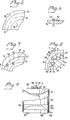
- Figure 1 an embodiment of a diaper of hour-glass configuration which has been chosen by way of example only and which has been provided with elastic tape in the crutch and side portions thereof so that when work the diaper seals as tightly as possible against the body.
- the disposable diaper 1 illustrated in Figure 1 comprises a liquid-permeable inner layer 2 of nonwoven or like material, i.e. a layer which faces the body of the wearer, and an impervious outer layer or topsheet 3 made of plastics film or plastics foil.
- a liquid absorbent pad 4 Arranged between the layers 2 and 3 is a liquid absorbent pad 4 of fluffed cellulose or like material.
- Elastic curved ribbons or filaments 5 are incorporated in the mutually joined side portions or panels 6 of the two layers 2 and 3, these side portions lying outside the pad 4.
- the ribbons or filaments 5, which are made of rubber or like material for example, are attached to the plastics web 3 in curved lines with the aid of an adhesive and prior to being attached are stretched so that after being firmly bonded to the plastics web they draw together the crutch part A of the diaper and optionally also the side parts 8 thereof, so that the edges of the diaper are gathered together, thereby to seal more efficiently against the body of the wearer.
- the stretched elastic ribbons 5 are laid along the outer contours of the diaper.
- each diaper may be provided with an elastic waist band firmly adhered to the two end parts of the outer plastics foil.
- the elastic ribbons comprise thin rubber ribbons which are bonded to the plastics web with a hot-melt adhesive, although it will be understood that the elastic ribbons may comprise any suitable materials whatsoever, such as, for example, an ethylene-propylene- rubber mixture (EPR) with an ethylene vinyl acetate extruded into thin ribbons which are stretched while applying heat thereto. The stretched ribbon is then cooled and remains stretched while retaining its elasticity. When subsequently heated the ribbon returns to its original length.
- EPR ethylene-propylene- rubber mixture
- the hot-melt adhesive can be replaced, for example, with double-sided adhesive foil, one surface of which adheres to the ribbon and the other surface of which is brought together with the aforesaid plastics web.
- the plastics web 10 passes from the drum 15 beneath a guide roller 16 and has then been provided on its undersurface with the somewhat tensioned elastic ribbons, from whence it passes over a freely-rotating reversing roller 17.
- the web 10 then passes from the reversing roller towards a working station of well known kind, in which the elastic ribbons lie on the upper side of the plastics web.
- a working station or a sequence of sequential working stations, there is applied a relatively thick layer of liquid-absorbent soft material, for example fluffed cellulose, together with the inner layer, whereafter the outer and inner layers are joined together and a finished diaper according to Figure 1 for example is punched from the resultant laminate.
- an electric motor 18 whose output shaft carries a sprocket wheel 19 which drives, via a chain 20, a further sprocket wheel 21 firmly mounted on a drive shaft 22 journalled in the frame structure 7 ( Figure 4).
- the drive shaft 22 also drives a chain 23 via a sprocket wheel (not shown) and a drive roller (not shown) for a drive belt 25, via a gearing 24, said belt extending over an upper drive roller 26 ( Figure 2).
- the drive rollers of the drive belt 25 are journalled on a frame 27 which can be pivoted around the lower drive roller and urged against the roll 9 carrying the plastics web with the aid of means not shown here.
- the drive belt 25 abutting the periphery of the roll 9 transfers a given drive force to the heavy roll 9, in order to facilitate withdrawal of the web 10 therefrom.
- a web take-off force is applied to the web 10 partly through the drum 15, against which the web 10 is held pressed by means of the guide rollers 14 and 16, and partly by means of drive rollers (not shown) between which the web passes and which, for example, are arranged upstream of the reversing roll 17.
- the drive shaft 22 is also provided with a sprocket wheel 28 ( Figure 4) which is firmly mounted on said shaft and which drives a sprocket wheel 30 via a chain 29.
- the chain wheel 30 is firmly mounted on a rotatable shaft 31 which extends transversely through the whole frame structure 7 and the end portions of which are rotatably journalled in bearing boxes located in vertical posts 32 and 33 fixed in the frame structure 7. Journalled on both ends of the shaft 31 are identical guide cylinders 34 and 35 respectively.
- Each guide cylinder is provided witn a respective continuous cam groove 36 and 37 comprising two identical parts each including 180aof the guide cylinder.
- Each such groove part has a form which corresponds to the predetermined paths 49, 50 of the elastic ribbon to be attached to the plastics web 10 (cf Figure 1).
- the two guide cylinders 34, 35 arranged on the outer surfaces of the frame structure 7 are firmly mounted on the shaft 31 and thus rotate synchronously with one another.
- the elastic ribbons attached to both sides of the diaper in the longitudinal direction therer of lie fully symmetrically around the longitudinal axis of the diaper.
- the two grooves 36 and 37 will have a correspondingly different curvature.
- the drum 15 is non-rotatably mounted on the shaft 31 in the frame 7 by means of robust spokes 38, 39 and 40 which extend from the centre part of the drum 15 and the inner end parts of which are joined with a hub 41 securely keyed to the shaft 31.
- the drum 15 has open ends through which are inserted two suction boxes 42 and 43 respectively.
- Each suction box 42, 43 has an upper edge part 44 (cf Figure 3) adapted to the inner surface 45 of the drum 15, said edge part 44 defining an open side of a respective box. Other sides are closed.
- the suction box 42 is connected to a suction source 47 via a suction pipe 46, while the suction box 43 is connected to the suction source 47 via a suction pipe 48.
- the suction source comprises, for example, a powerful fan or centrifugal pump adapted to create a desired subpressure in the two suction boxes 42 and 43 arranged on both sides of the carrier means 38, 39, 40 of the drum 15.
- the peripheral surface of the drum 15 has arranged therein grooves 49 and 50 defining said predetermined paths and of the same configuration as the cam grooves 36 and 37 respectively. It is, howe J er, emphasized that the drum can be perfectly smooth and that the elastic bands need not be fed into grooves in the surface of the drum.
- Each of these grooves 49 and 50 is intended to accomodate at least one elastic ribbon 51, see in particular Figure 4, which are withdrawn from a reel 52 by means of two mutually abutting driven rollers 53 and 54, or drawn from a box and fed in between the rollers 53, 54.
- the two rollers 53 and 54 are journalled in the frame structure 7 and are driven from a direct- current motor 55, as indicated in Figure 4.
- Each carriage, 58, 59 is provided with a dogging means, for example the dogging means 60 of the carriage 59, which are firmly mounted on the carriage and project into the respective allotted cam groove 36 or 37.
- a dogging means for example the dogging means 60 of the carriage 59, which are firmly mounted on the carriage and project into the respective allotted cam groove 36 or 37.
- the shaft 31 rotates, and therewith also the drum 15 and the guide cylinders 34 and 35
- the two carriages 58 and 49 are moved towards and away from each other on the two guides 56, 57.
- Mounted on the carriage 58 and 59 are respective adhesive nozzles 61 and 62, said nozzles being located such that their outlet orifices follow the ribbon grooves 49 and 50 during movement of the carriages.
- the two nozzles 61 and 62 are supplied with hot thermoplastic adhesive under pressure through conduits, for example the conduit 63 in Figure 3 from a source not shown. Since two elastic ribbons 51 are to be withdrawn, one for each groove 49, 50, two reels 52 are provided. Each ribbon is withdrawn from its respective reel by means of the two drive rollers 53, 54 which hold the ribbon firmly therebetween and feed the ribbon over a guide roller 64 into its allotted groove 49, 50.
- the shaft 31, and therewith the drum 15 and the guide cylinders 34, 35 are assumed here to be driven at a constant, given speed which is adapted to the rate at which work is carried out in subsequent stations.
- each elastic ribbon 51 is to be attached to the plastics web 10 in a somewhat tensioned state, and possibly under a tension which varies along the ribbon length, the rollers 53 and 54 must be driven at a speed such that the speed at which the ribbon 51 is advanced is slower than the peripheral speed of the drum 15.
- adhesive is applied to the upper surface of the ribbon and the ribbon pressed by the pressure roller 14 onto the undersurface of the plastics web 10.
- the illustrated embodiment includes a cooling box 65 ( Figure 3) which is connected to a source 66 of cooling air and arranged above the drum 15 in order to cool the hot, melt adhesive as quickly as possible.
- the ribbon 5 which as will be understood need not be planar but may have the form of a filament of substantially circular cross-section, in the groove on the drum 15 through a distance equal to about 180 0 , although this distance may naturally vary, inter alia in dependence on the diameter of the drum and the length of the diaper.
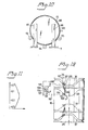
- Figures 5 and 6 illustrate a pronounced curvature in the groove 49 and the manner in which an inserted ribbon 51 having a width exceeding its thickness behaves.
- the tension in the ribbon 51 is greater on the outside of the centre line 67 of the groove 49 than on the inside of the centre line, and as mentioned in the introduction and as illustrated in Figure 6 the ribbon 51 will be lifted up on the outside of the curve, and in an extreme case will be rolled or tilted over the radially inward ribbon portion, resulting in poor adhesion to the plastics web 10, or in a practically negligible bond.
- suction boxes 42 and 43 and suction openings for example the openings 68, 69, 70, 71 in the preferably planar bottom 72 of the grooves 49 and 50, extending substantially along the whole length of the groove ( Figure 7) are arranged in accordance with the invention to avoid this drawback.
- These openings 68, 71 communicate with the respective interiors of the suction boxes and will thus draw the non- adhesive surface of the entire ribbon 51 firmly against the groove bottom, therewith to hold the ribbon in a planar and non-slidable position in the groove.
- the openings must at least be arranged on the groove portion 49' ( Figure 7) distal from the centre of curvature, although openings, such as the opening 73, 74, 75 and 76, are also preferably arranged on the innermost groove part 49" ( Figure 8), thereby to obtain positive retention of the edge portions of the ribbon on both sides of the centre line, which further reduces the risk of the tensioned ribbon from sliding and tilting in the groove and therewith moving relative to the web 10 which moves at a constant speed.
- the inner and outer openings are suitably displaced relative to one another, as illustrated in Figure 8, and in one preferred embodiment the inner and outer openings are connected with one another by means of shallow grooves, for example the grooves 80 and 81, which cross the groove bottom 22.
- the suction openings in the outer and inner rows respectively may be connected together directly, as illustrated by the broken lines 82 and 83 which indicate shallow grooves formed by grinding the groove bottom 72. Practical tests have shown that such grooves 82 extending in the longitudinal direction of the tape 51 between the suction openings provide a good effect with respect to preventing upward bending of the outer ribbon edge, shown in Figure 6, while grooves 81 extending across the width of the ribbon, on the other hand, are much more effective in preventing sliding of the ribbon than the grooves 82.
- FIG. 3 The principle by which the ribbon 51 is imparted in the illustrated embodiment with a varying tension such that the finished diaper, or some other manufactured liquid-absorbing product, has a region of greatest tension in the crutch part of the diaper is illustrated in a highly simplified manner in Figure 3.
- the figure illustrates the cam grooves 36 of the guide cylinder 34, these grooves accomodating a dogging means 84, which in turn adjusts a potentiometer 85 fixedly mounted in relation to the cam groove 36.
- the potentiometer 85 regulates the voltage to the direct current motor 55 which drives the feed rollers 53, 54.
- the ribbon 51 When the setting means of the potentiometer 85 is located within the region 36" the ribbon 51 shall be imparted a continuously increasing tensile force so that when the setting means reaches the horizontal region 36" shown in the figure the achieved maximum tension is maintained throughout the whole of the crutch part G1-G2 ( Figure 1).
- the setting means 84 then reaches the upwardly directed part of the cam groove and the tensile force in the ribbon 51 is progressively decreased to the minimum, constantly maintained tensile force, i.e. the speed of the motor 55 is progressively increased.
- the ribbon tension may be given the appearance illustrated in Figure 11, for example, in which the length markings G1-G4 shown in Figure 1 are plotted along the Y axis and the tensile force is plotted along the X-axis.
- the ribbon or band is held by suction forces along its length in the predetermined curved path 49 or 50 and therefore the varying tension forces will be maintained.
- the ribbon 51 while lying on the outer cylindrical surface of the drum 15 will be held firmly by suction at the same time as all suction effect ceases on the part departing from the drum, this part thus not being subjected to forces capable of pulling the ribbon loose from the web 10.
- the grooves illustrated in Figure 8 connecting the suction openings with one another are so shallow that the ribbon material is drawn down into the grooves and seals thereagainst.
- FIGS 9 and 10 illustrate a modified drum having a rear side wall 90 with a hub 91 to which the drive shaft 31 is firmly connected.
- the hub 90 is mounted for rotation in a journal bearing 92 attached to the machine-frame structure 7 in a manner not shown.
- the other end part of the drum 15 is open and freely-running rollers 93, 94, 95 are journalled in the frame structure and support this end part.
- the suction box 96 is carried by two bracket means 97, 98, firmly mounted to the frame structure 7.
- the interior of the suction box 96 is connected to a suction source via a conduit 100.
- a suction source Arranged in the outer cylindrical surface of the suction box 96 are two openings which include about 180 0 of said outer cylindrical surface and lie in the movement path of the groove 49 and 50 respectively.
- the opening 101 for the groove 50 is shown in Figure 9.
- the guide cylinder 34 in Figure 4 is assumed to be provided, while sensing of the guide curve 36 is assumed to take place with the aid of a photocell, which in turn delivers a control signal to two electric motors for guiding the two aforementioned carriages 61 and 62 towards and away from each other.
- the curve 36 need not comprise a milled groove, but may comprise a track marked with a colouring agent.
- the requisite movements of the carriages 61 and 62 may also be effected with the aid of a dataprocessor containing the requisite control information.
- Figure 12 illustrates the one carriage 59, on which there is rotatably mounted a table 103, which is arranged for rotation about a central shaft or axis 104.
- the table 103 carries the adhesive nozzle 62, a guide roller 64 and drive rollers 53, 54, ( Figures 3 and 4) and these elements will thus be rotated as a unit and determine the infeed direction of the ribbon 51 and the adhesive string, this direction being indicated in Figure 12 by the arrow F and corresponds to the direction F' of the groove 49 at the infeed location.
- the carriage 56 ( Figure 4) is provided with a corresponding table, carrying the adhesive nozzle 61 and the ribbon-feed and ribbon-alignment rollers for the ribbon 51, which is introduced into the groove 50.
- Figure 12 illustrates the dogging means 60 ( Figure 4) which, as previously described, guides the movement of carriage 59 parallel with the axis of the drum 15 and which comprises a freely rotatable wheel having a diameter corresponding to the width of the cam groove 36.
- the wheel 60 is rotatably journalled centrally on a pivot arm 105, one end of which is pivotably connected to a guide arm 106 and the other end of which carries a freely rotatable follower wheel 107 having a smaller diameter than the width of the cam groove 36, so that the guide means formed by the wheels 60, 107 can pass freely through curves of small radii.
- a tension spring 108 which holds the wheel 107 pressed against the inner wall of the groove 36.
- the other end of the guide arm 106 is pivotably connected to a further pivot arm 109 the free end of which carries a follower wheel 110 which co-acts with the groove 49.
- the follower wheel 110 is journalled in a holder 111.
- the described and well known parallelogram-guide mechanism ensures that the rotary axis of the wheel 110 always lies at right angles to F1, and when the holder 111 is connected to the table 103 via a linkage system 112, the table 103 will thus always be adjusted in dependence on the curvature of the groove part to which ribbon and adhesive are fed at that moment in time.
- the table on the carriage not shown in Figure 13 is guided with the aid of a corresponding parallelogram-link system.
- cam grooves 36 and 37 there can be used a purely electronic guide means incorporating guide information stored in a detaprocessor and utilised to instigate translatory movements of the carriages 58, 59 and rotatory movements of the tables, for examples the table 103, via drive motors.
- Such dataorised movement is particularly suitable when the fixed paths 49, 50 are not formed by grooves provided in the outer cylindrical surface of the drum 15, but simply have the form of the described suction openings in said surface.
- the ribbon must be placed analogously with what has been described with reference to Figure 12, i.e. the position of the ribbon at the point of application must, at each moment in time, correspond to the determined shape of the path 49 and 50 respectively.
Landscapes
- Engineering & Computer Science (AREA)
- Mechanical Engineering (AREA)
- Health & Medical Sciences (AREA)
- General Health & Medical Sciences (AREA)
- Veterinary Medicine (AREA)
- Biomedical Technology (AREA)
- Heart & Thoracic Surgery (AREA)
- Vascular Medicine (AREA)
- Life Sciences & Earth Sciences (AREA)
- Animal Behavior & Ethology (AREA)
- Manufacturing & Machinery (AREA)
- Public Health (AREA)
- Epidemiology (AREA)
- Absorbent Articles And Supports Therefor (AREA)
- Adornments (AREA)
- Finger-Pressure Massage (AREA)
- Orthopedics, Nursing, And Contraception (AREA)
- Ultra Sonic Daignosis Equipment (AREA)
- Breeding Of Plants And Reproduction By Means Of Culturing (AREA)
- Organic Low-Molecular-Weight Compounds And Preparation Thereof (AREA)
- Vehicle Interior And Exterior Ornaments, Soundproofing, And Insulation (AREA)
- Protection Of Pipes Against Damage, Friction, And Corrosion (AREA)
- Treatment Of Fiber Materials (AREA)
Priority Applications (1)
| Application Number | Priority Date | Filing Date | Title |
|---|---|---|---|
| AT85850323T ATE40510T1 (de) | 1984-11-28 | 1985-10-15 | Verfahren zum anbringen eines elastischen elementes an eine kunststoffbahn mittels klebstoffs. |
Applications Claiming Priority (2)
| Application Number | Priority Date | Filing Date | Title |
|---|---|---|---|
| SE8405999A SE449820B (sv) | 1984-11-28 | 1984-11-28 | Anordning for att medelst lim festa ett elastiskt band pa en plastbana vid tillverkning av blojor o d |
| SE8405999 | 1984-11-28 |
Publications (2)
| Publication Number | Publication Date |
|---|---|
| EP0183662A1 true EP0183662A1 (de) | 1986-06-04 |
| EP0183662B1 EP0183662B1 (de) | 1989-02-01 |
Family
ID=20357939
Family Applications (1)
| Application Number | Title | Priority Date | Filing Date |
|---|---|---|---|
| EP85850323A Expired EP0183662B1 (de) | 1984-11-28 | 1985-10-15 | Verfahren zum Anbringen eines elastischen Elementes an eine Kunststoffbahn mittels Klebstoffs |
Country Status (9)
| Country | Link |
|---|---|
| US (1) | US4675068A (de) |
| EP (1) | EP0183662B1 (de) |
| AT (1) | ATE40510T1 (de) |
| CA (1) | CA1242629A (de) |
| DE (1) | DE3567999D1 (de) |
| DK (1) | DK549185A (de) |
| FI (1) | FI854101L (de) |
| NO (1) | NO157726C (de) |
| SE (1) | SE449820B (de) |
Cited By (4)
| Publication number | Priority date | Publication date | Assignee | Title |
|---|---|---|---|---|
| EP0282196A1 (de) * | 1987-03-09 | 1988-09-14 | Paper Converting Machine Company | Verfahren und Vorrichtung zur Herstellung elastischer Windeln |
| GR890100205A (en) * | 1988-04-11 | 1990-01-31 | Moelnlycke Ab | Apparatus and method for laying elastic thread on a web of material |
| EP0464865A2 (de) * | 1985-10-28 | 1992-01-08 | Kimberly-Clark Corporation | Verfahren und Vorrichtung zum Aufbringen von profiliertem elastischem Material auf einen Träger |
| WO1996004874A1 (en) * | 1994-08-12 | 1996-02-22 | Kimberly-Clark Worldwide, Inc. | Method for applying an elastic member to a moving substrate |
Families Citing this family (67)
| Publication number | Priority date | Publication date | Assignee | Title |
|---|---|---|---|---|
| US4726807A (en) * | 1986-04-10 | 1988-02-23 | Weyerhaeuser Company | Diaper with elastic margins |
| US4764242A (en) * | 1986-12-18 | 1988-08-16 | The Kendall Company | Adhesive applying apparatus |
| JPH0761349B2 (ja) * | 1987-07-03 | 1995-07-05 | ユニ・チャ−ム株式会社 | 移動ウエブへの弾性バンド貼着方法および装置 |
| JP2609252B2 (ja) * | 1987-08-18 | 1997-05-14 | ユニ・チャーム 株式会社 | 移動ウエブへの弾性バンド貼着装置 |
| US4863542A (en) * | 1988-01-19 | 1989-09-05 | Kimberly-Clark Corporation | Method and apparatus for applying discreet elastic strips to a stationary web |
| US4915767A (en) * | 1988-11-17 | 1990-04-10 | Kimberly-Clark Corporation | Apparatus for applying an elastic in a curved pattern to a moving web |
| CA2050782C (en) * | 1990-09-13 | 1997-01-28 | Takamitsu Igaue | Disposable garments and method for attachment of elastic members around leg-holes thereof |
| US5779689A (en) * | 1990-10-26 | 1998-07-14 | Peaudouce | Diapers with elasticized crotch and end regions and a process and apparatus for the continuous manufacture thereof |
| ZA92308B (en) | 1991-09-11 | 1992-10-28 | Kimberly Clark Co | Thin absorbent article having rapid uptake of liquid |
| US5389173A (en) * | 1992-12-02 | 1995-02-14 | Paper Converting Machine Company | Apparatus and process for making disposable diaper type products |
| US5500075A (en) * | 1994-04-26 | 1996-03-19 | Paragon Trade Brands, Inc. | Leg elastic applicator which maintains the spacing between the elastics substantially constant |
| US6387471B1 (en) | 1999-03-31 | 2002-05-14 | Kimberly-Clark Worldwide, Inc. | Creep resistant composite elastic material with improved aesthetics, dimensional stability and inherent latency and method of producing same |
| US6547915B2 (en) | 1999-04-15 | 2003-04-15 | Kimberly-Clark Worldwide, Inc. | Creep resistant composite elastic material with improved aesthetics, dimensional stability and inherent latency and method of producing same |
| US6287409B1 (en) * | 1999-12-23 | 2001-09-11 | Kimberely-Clark Worldwide, Inc. | Methods and apparatus for applying an elastic material in a curvilinear pattern on a continuously moving substrate |
| ES2169648B1 (es) * | 2000-02-01 | 2003-02-16 | Com De Tecnologia Sanitaria S | Maquina para la fabricacion de productos multicapa, tales como compresas, protectores higienicos o apositos. |
| US6969441B2 (en) | 2000-05-15 | 2005-11-29 | Kimberly-Clark Worldwide, Inc. | Method and apparatus for producing laminated articles |
| US6833179B2 (en) | 2000-05-15 | 2004-12-21 | Kimberly-Clark Worldwide, Inc. | Targeted elastic laminate having zones of different basis weights |
| US8182457B2 (en) | 2000-05-15 | 2012-05-22 | Kimberly-Clark Worldwide, Inc. | Garment having an apparent elastic band |
| US7316842B2 (en) | 2002-07-02 | 2008-01-08 | Kimberly-Clark Worldwide, Inc. | High-viscosity elastomeric adhesive composition |
| US7335273B2 (en) | 2002-12-26 | 2008-02-26 | Kimberly-Clark Worldwide, Inc. | Method of making strand-reinforced elastomeric composites |
| US7097725B2 (en) * | 2002-10-16 | 2006-08-29 | Zuiko Corporation | Placement device |
| US7601657B2 (en) | 2003-12-31 | 2009-10-13 | Kimberly-Clark Worldwide, Inc. | Single sided stretch bonded laminates, and methods of making same |
| US8417374B2 (en) | 2004-04-19 | 2013-04-09 | Curt G. Joa, Inc. | Method and apparatus for changing speed or direction of an article |
| US7638014B2 (en) | 2004-05-21 | 2009-12-29 | Curt G. Joa, Inc. | Method of producing a pants-type diaper |
| US20060258249A1 (en) * | 2005-05-11 | 2006-11-16 | Fairbanks Jason S | Elastic laminates and process for producing same |
| US9622918B2 (en) * | 2006-05-18 | 2017-04-18 | Curt G. Joe, Inc. | Methods and apparatus for application of nested zero waste ear to traveling web |
| US7780052B2 (en) * | 2006-05-18 | 2010-08-24 | Curt G. Joa, Inc. | Trim removal system |
| US10456302B2 (en) | 2006-05-18 | 2019-10-29 | Curt G. Joa, Inc. | Methods and apparatus for application of nested zero waste ear to traveling web |
| US9433538B2 (en) | 2006-05-18 | 2016-09-06 | Curt G. Joa, Inc. | Methods and apparatus for application of nested zero waste ear to traveling web and formation of articles using a dual cut slip unit |
| US7731815B2 (en) * | 2006-11-06 | 2010-06-08 | The Procter & Gamble Company | Method and apparatus for nonlinear laying of material |
| EP2486904A3 (de) | 2007-02-21 | 2013-02-27 | Joa, Curt G., Inc. | Verfahren und Vorrichtung für die Positionierung eines Einsatzes mit Einzelübertragung |
| US9550306B2 (en) | 2007-02-21 | 2017-01-24 | Curt G. Joa, Inc. | Single transfer insert placement and apparatus with cross-direction insert placement control |
| US9944487B2 (en) | 2007-02-21 | 2018-04-17 | Curt G. Joa, Inc. | Single transfer insert placement method and apparatus |
| US8398793B2 (en) | 2007-07-20 | 2013-03-19 | Curt G. Joa, Inc. | Apparatus and method for minimizing waste and improving quality and production in web processing operations |
| US9387131B2 (en) | 2007-07-20 | 2016-07-12 | Curt G. Joa, Inc. | Apparatus and method for minimizing waste and improving quality and production in web processing operations by automated threading and re-threading of web materials |
| US8182624B2 (en) * | 2008-03-12 | 2012-05-22 | Curt G. Joa, Inc. | Registered stretch laminate and methods for forming a registered stretch laminate |
| US20100193138A1 (en) * | 2009-01-30 | 2010-08-05 | Joseph Allen Eckstein | System for High-Speed Continuous Application of a Strip Material to a Moving Sheet-Like Substrate Material at Laterally Shifting Locations |
| US20100193135A1 (en) * | 2009-01-30 | 2010-08-05 | Joseph Allen Eckstein | System and Method for High-Speed Continuous Application of a Strip Material to a Moving Sheet-Like Substrate Material at Laterally Shifting Locations |
| US8171972B2 (en) | 2009-01-30 | 2012-05-08 | The Procter & Gamble Company | Strip guide for high-speed continuous application of a strip material to a moving sheet-like substrate material at laterally shifting locations |
| US8182627B2 (en) * | 2009-01-30 | 2012-05-22 | The Procter & Gamble Company | Method for high-speed continuous application of a strip material to a substrate along an application path on the substrate |
| CN102458336B (zh) * | 2009-04-30 | 2014-11-12 | Sca卫生用品公司 | 用于提供弹性幅的方法 |
| US8673098B2 (en) | 2009-10-28 | 2014-03-18 | Curt G. Joa, Inc. | Method and apparatus for stretching segmented stretchable film and application of the segmented film to a moving web |
| US9089453B2 (en) | 2009-12-30 | 2015-07-28 | Curt G. Joa, Inc. | Method for producing absorbent article with stretch film side panel and application of intermittent discrete components of an absorbent article |
| US8460495B2 (en) | 2009-12-30 | 2013-06-11 | Curt G. Joa, Inc. | Method for producing absorbent article with stretch film side panel and application of intermittent discrete components of an absorbent article |
| US8663411B2 (en) | 2010-06-07 | 2014-03-04 | Curt G. Joa, Inc. | Apparatus and method for forming a pant-type diaper with refastenable side seams |
| US9603752B2 (en) | 2010-08-05 | 2017-03-28 | Curt G. Joa, Inc. | Apparatus and method for minimizing waste and improving quality and production in web processing operations by automatic cuff defect correction |
| US20120273129A1 (en) * | 2010-10-27 | 2012-11-01 | Curt G. Joa, Inc. | Apparatus and method for the application of a curved ribbon to a traveling web |
| US8702887B2 (en) | 2010-12-17 | 2014-04-22 | Kimberly-Clark Worldwide, Inc. | Apparatus for and method of applying ribbon in a nonlinear pattern to a web |
| US8720518B2 (en) | 2010-12-17 | 2014-05-13 | Kimberly-Clark Worldwide, Inc. | Apparatus for bonding ribbon in a nonlinear pattern to a web |
| US9566193B2 (en) | 2011-02-25 | 2017-02-14 | Curt G. Joa, Inc. | Methods and apparatus for forming disposable products at high speeds with small machine footprint |
| US8656817B2 (en) | 2011-03-09 | 2014-02-25 | Curt G. Joa | Multi-profile die cutting assembly |
| USD684613S1 (en) | 2011-04-14 | 2013-06-18 | Curt G. Joa, Inc. | Sliding guard structure |
| US8820380B2 (en) | 2011-07-21 | 2014-09-02 | Curt G. Joa, Inc. | Differential speed shafted machines and uses therefor, including discontinuous and continuous side by side bonding |
| JP5883155B2 (ja) | 2011-11-30 | 2016-03-09 | ザ プロクター アンド ギャンブルカンパニー | 小型使い捨てプルオンおむつ |
| US10751220B2 (en) | 2012-02-20 | 2020-08-25 | Curt G. Joa, Inc. | Method of forming bonds between discrete components of disposable articles |
| US9809414B2 (en) | 2012-04-24 | 2017-11-07 | Curt G. Joa, Inc. | Elastic break brake apparatus and method for minimizing broken elastic rethreading |
| EP2866753A1 (de) | 2012-06-29 | 2015-05-06 | The Procter & Gamble Company | System und verfahren für kontinuierliche hochgeschwindigkeitsanwendung eines streifenmaterials auf ein bewegtes blattförmiges substratmaterial |
| US9283683B2 (en) | 2013-07-24 | 2016-03-15 | Curt G. Joa, Inc. | Ventilated vacuum commutation structures |
| USD703711S1 (en) | 2013-08-23 | 2014-04-29 | Curt G. Joa, Inc. | Ventilated vacuum communication structure |
| USD704237S1 (en) | 2013-08-23 | 2014-05-06 | Curt G. Joa, Inc. | Ventilated vacuum commutation structure |
| USD703247S1 (en) | 2013-08-23 | 2014-04-22 | Curt G. Joa, Inc. | Ventilated vacuum commutation structure |
| USD703248S1 (en) | 2013-08-23 | 2014-04-22 | Curt G. Joa, Inc. | Ventilated vacuum commutation structure |
| USD703712S1 (en) | 2013-08-23 | 2014-04-29 | Curt G. Joa, Inc. | Ventilated vacuum commutation structure |
| US9289329B1 (en) | 2013-12-05 | 2016-03-22 | Curt G. Joa, Inc. | Method for producing pant type diapers |
| WO2017019544A1 (en) | 2015-07-24 | 2017-02-02 | Curt G. Joa, Inc. | Vacuum commutation apparatus and methods |
| KR101873400B1 (ko) | 2015-09-29 | 2018-08-02 | 킴벌리-클라크 월드와이드, 인크. | 회전 밸브를 구비한 접착제 도포 기구 |
| US11737930B2 (en) | 2020-02-27 | 2023-08-29 | Curt G. Joa, Inc. | Configurable single transfer insert placement method and apparatus |
Citations (4)
| Publication number | Priority date | Publication date | Assignee | Title |
|---|---|---|---|---|
| FR2177425A1 (en) * | 1971-10-13 | 1973-11-09 | Elastelle Fontanille | Disposable garments - having elasticated borders |
| GB2021469A (en) * | 1978-05-25 | 1979-12-05 | Moelnlycke Ab | Method and device for cutting out pieces from a web of material |
| US4216687A (en) * | 1978-03-21 | 1980-08-12 | Johnson & Johnson | Method for shaping and/or cutting batts of loosely compacted fibrous materials |
| EP0108173A1 (de) * | 1981-03-09 | 1984-05-16 | Reinhardt Nils Sabee | Verfahren und Vorrichtung zum Anbringen elastischer Streifen auf Bahnen |
Family Cites Families (5)
| Publication number | Priority date | Publication date | Assignee | Title |
|---|---|---|---|---|
| US2782574A (en) * | 1954-09-16 | 1957-02-26 | Gen Dynamics Corp | Work holder |
| FR2112075B1 (de) * | 1970-09-18 | 1973-12-07 | Elastelle Fontanille Il | |
| US4207998A (en) * | 1977-05-16 | 1980-06-17 | Bachofen & Meier, Maschinenfabrik | Vacuum roller |
| AU5681680A (en) * | 1979-10-16 | 1981-04-30 | Riegel Textile Corp. | Diaper |
| US4479836A (en) * | 1980-05-16 | 1984-10-30 | Johnson & Johnson Baby Products Company | Method for effecting securement of alternating stretched and unstretched elastic ribbon to a moving web |
-
1984
- 1984-11-28 SE SE8405999A patent/SE449820B/sv not_active IP Right Cessation
-
1985
- 1985-10-15 DE DE8585850323T patent/DE3567999D1/de not_active Expired
- 1985-10-15 EP EP85850323A patent/EP0183662B1/de not_active Expired
- 1985-10-15 AT AT85850323T patent/ATE40510T1/de not_active IP Right Cessation
- 1985-10-21 FI FI854101A patent/FI854101L/fi not_active IP Right Cessation
- 1985-10-22 US US06/790,012 patent/US4675068A/en not_active Expired - Fee Related
- 1985-10-29 CA CA000494136A patent/CA1242629A/en not_active Expired
- 1985-11-27 NO NO854742A patent/NO157726C/no unknown
- 1985-11-27 DK DK549185A patent/DK549185A/da not_active Application Discontinuation
Patent Citations (4)
| Publication number | Priority date | Publication date | Assignee | Title |
|---|---|---|---|---|
| FR2177425A1 (en) * | 1971-10-13 | 1973-11-09 | Elastelle Fontanille | Disposable garments - having elasticated borders |
| US4216687A (en) * | 1978-03-21 | 1980-08-12 | Johnson & Johnson | Method for shaping and/or cutting batts of loosely compacted fibrous materials |
| GB2021469A (en) * | 1978-05-25 | 1979-12-05 | Moelnlycke Ab | Method and device for cutting out pieces from a web of material |
| EP0108173A1 (de) * | 1981-03-09 | 1984-05-16 | Reinhardt Nils Sabee | Verfahren und Vorrichtung zum Anbringen elastischer Streifen auf Bahnen |
Cited By (6)
| Publication number | Priority date | Publication date | Assignee | Title |
|---|---|---|---|---|
| EP0464865A2 (de) * | 1985-10-28 | 1992-01-08 | Kimberly-Clark Corporation | Verfahren und Vorrichtung zum Aufbringen von profiliertem elastischem Material auf einen Träger |
| EP0464865A3 (en) * | 1985-10-28 | 1992-08-26 | Kimberly-Clark Corporation | Method and apparatus for applying contoured elastic to a substrate |
| EP0282196A1 (de) * | 1987-03-09 | 1988-09-14 | Paper Converting Machine Company | Verfahren und Vorrichtung zur Herstellung elastischer Windeln |
| GR890100205A (en) * | 1988-04-11 | 1990-01-31 | Moelnlycke Ab | Apparatus and method for laying elastic thread on a web of material |
| US5236539A (en) * | 1988-04-11 | 1993-08-17 | Rogberg John A | Apparatus for laying elastic thread on a web of material |
| WO1996004874A1 (en) * | 1994-08-12 | 1996-02-22 | Kimberly-Clark Worldwide, Inc. | Method for applying an elastic member to a moving substrate |
Also Published As
| Publication number | Publication date |
|---|---|
| SE449820B (sv) | 1987-05-25 |
| DK549185D0 (da) | 1985-11-27 |
| ATE40510T1 (de) | 1989-02-15 |
| EP0183662B1 (de) | 1989-02-01 |
| SE8405999D0 (sv) | 1984-11-28 |
| FI854101A0 (fi) | 1985-10-21 |
| FI854101L (fi) | 1986-05-29 |
| DK549185A (da) | 1986-05-29 |
| SE8405999L (sv) | 1986-05-29 |
| NO854742L (no) | 1986-05-29 |
| NO157726B (no) | 1988-02-01 |
| NO157726C (no) | 1988-05-11 |
| US4675068A (en) | 1987-06-23 |
| DE3567999D1 (en) | 1989-03-09 |
| CA1242629A (en) | 1988-10-04 |
Similar Documents
| Publication | Publication Date | Title |
|---|---|---|
| EP0183662B1 (de) | Verfahren zum Anbringen eines elastischen Elementes an eine Kunststoffbahn mittels Klebstoffs | |
| US5043036A (en) | Width stretching device | |
| US5545285A (en) | Waist elastic applicator for diaper or similar article | |
| US5531850A (en) | Apparatus and method for applying transverse tensioned elastic | |
| US2702406A (en) | Apparatus for stretching sheet material | |
| US3988194A (en) | Apparatus and method for applying label stock | |
| JPS602570A (ja) | 両面接着テ−プ自動貼着装置 | |
| US6264132B1 (en) | Method and device for grasping part of an outer layer of a strip of material on a supply roll | |
| JP2793166B2 (ja) | 貯蔵ウエブロールから繰り出されるウエブの部分を処理するための装置 | |
| CN109626084A (zh) | 一种胶带复卷机自动贴标纸装置 | |
| CN212768864U (zh) | 一种自动换卷拼接装置 | |
| CA1227963A (en) | Pads and their formation | |
| US3935057A (en) | Apparatus for securing the free end of a roll of fibrous web material | |
| JP4583683B2 (ja) | 使い捨て吸収用品の製造方法及び装置 | |
| CN220199671U (zh) | 一种贴剂自动包装设备 | |
| EP1016394B1 (de) | Verfahren und Vorrichtung zum Anbringen von elastischen Elementen | |
| US5102486A (en) | Loop applying assembly | |
| EP0827453B1 (de) | Verfahren zur behandlung einer materialbahn auf einer zentralen behandlungstrommel | |
| EP0846621A1 (de) | Vorrichtung zum Anbringen eines Papierklebestreifens auf einer zu schliessenden Schachtel | |
| MXPA97008692A (en) | Device and method for converting a network in a processing drum cent | |
| JPS6039618B2 (ja) | ロ−ル巻仕舞端接着装置 | |
| EP0810947B1 (de) | Vorrichtung und verfahren in einer verpackungsmachine | |
| RU2301765C2 (ru) | Способ наклеивания этикеток и устройство для его осуществления | |
| JP2584446B2 (ja) | 引き伸ばされた弾性帯片を連続的に移動するように駆動されたシートに固定するための弾性帯片固定装置、及び、おむつ製造装置 | |
| CN219489102U (zh) | 一种镭射复膜导膜辊走膜辅助结构 |
Legal Events
| Date | Code | Title | Description |
|---|---|---|---|
| PUAI | Public reference made under article 153(3) epc to a published international application that has entered the european phase |
Free format text: ORIGINAL CODE: 0009012 |
|
| AK | Designated contracting states |
Kind code of ref document: A1 Designated state(s): AT BE CH DE FR GB IT LI LU NL SE |
|
| 17P | Request for examination filed |
Effective date: 19860616 |
|
| 17Q | First examination report despatched |
Effective date: 19871120 |
|
| GRAA | (expected) grant |
Free format text: ORIGINAL CODE: 0009210 |
|
| AK | Designated contracting states |
Kind code of ref document: B1 Designated state(s): AT BE CH DE FR GB IT LI LU NL SE |
|
| REF | Corresponds to: |
Ref document number: 40510 Country of ref document: AT Date of ref document: 19890215 Kind code of ref document: T |
|
| ITF | It: translation for a ep patent filed |
Owner name: DOTT. GIOVANNI LECCE & C. |
|
| ET | Fr: translation filed | ||
| REF | Corresponds to: |
Ref document number: 3567999 Country of ref document: DE Date of ref document: 19890309 |
|
| REG | Reference to a national code |
Ref country code: GB Ref legal event code: 732 |
|
| REG | Reference to a national code |
Ref country code: CH Ref legal event code: PUE Owner name: FIBRE CONVERTING MACHINERY AB |
|
| RAP2 | Party data changed (patent owner data changed or rights of a patent transferred) |
Owner name: FIBRE CONVERTING MACHINERY AB |
|
| REG | Reference to a national code |
Ref country code: FR Ref legal event code: TP |
|
| NLS | Nl: assignments of ep-patents |
Owner name: FIBRE CONVERTING MACHINERY AB TE SOLLENTUNA, ZWEDE |
|
| ITPR | It: changes in ownership of a european patent |
Owner name: CESSIONE;FIBRE CONVERTING MACHINERY AB |
|
| PGFP | Annual fee paid to national office [announced via postgrant information from national office to epo] |
Ref country code: LU Payment date: 19891011 Year of fee payment: 5 |
|
| PGFP | Annual fee paid to national office [announced via postgrant information from national office to epo] |
Ref country code: AT Payment date: 19891018 Year of fee payment: 5 |
|
| PGFP | Annual fee paid to national office [announced via postgrant information from national office to epo] |
Ref country code: BE Payment date: 19891025 Year of fee payment: 5 |
|
| PGFP | Annual fee paid to national office [announced via postgrant information from national office to epo] |
Ref country code: CH Payment date: 19891026 Year of fee payment: 5 |
|
| ITTA | It: last paid annual fee | ||
| PG25 | Lapsed in a contracting state [announced via postgrant information from national office to epo] |
Ref country code: LU Free format text: LAPSE BECAUSE OF NON-PAYMENT OF DUE FEES Effective date: 19891031 |
|
| PGFP | Annual fee paid to national office [announced via postgrant information from national office to epo] |
Ref country code: NL Payment date: 19891031 Year of fee payment: 5 Ref country code: GB Payment date: 19891031 Year of fee payment: 5 Ref country code: FR Payment date: 19891031 Year of fee payment: 5 Ref country code: DE Payment date: 19891031 Year of fee payment: 5 |
|
| PLBE | No opposition filed within time limit |
Free format text: ORIGINAL CODE: 0009261 |
|
| STAA | Information on the status of an ep patent application or granted ep patent |
Free format text: STATUS: NO OPPOSITION FILED WITHIN TIME LIMIT |
|
| 26N | No opposition filed | ||
| PGFP | Annual fee paid to national office [announced via postgrant information from national office to epo] |
Ref country code: SE Payment date: 19900927 Year of fee payment: 6 |
|
| PG25 | Lapsed in a contracting state [announced via postgrant information from national office to epo] |
Ref country code: GB Effective date: 19901015 Ref country code: AT Effective date: 19901015 |
|
| PG25 | Lapsed in a contracting state [announced via postgrant information from national office to epo] |
Ref country code: LI Effective date: 19901031 Ref country code: CH Effective date: 19901031 Ref country code: BE Effective date: 19901031 |
|
| BERE | Be: lapsed |
Owner name: FIBRE CONVERTING MACHINERY A.B. Effective date: 19901031 |
|
| PG25 | Lapsed in a contracting state [announced via postgrant information from national office to epo] |
Ref country code: NL Effective date: 19910501 |
|
| GBPC | Gb: european patent ceased through non-payment of renewal fee | ||
| NLV4 | Nl: lapsed or anulled due to non-payment of the annual fee | ||
| PG25 | Lapsed in a contracting state [announced via postgrant information from national office to epo] |
Ref country code: FR Effective date: 19910628 |
|
| REG | Reference to a national code |
Ref country code: CH Ref legal event code: PL |
|
| PG25 | Lapsed in a contracting state [announced via postgrant information from national office to epo] |
Ref country code: DE Effective date: 19910702 |
|
| REG | Reference to a national code |
Ref country code: FR Ref legal event code: ST |
|
| PG25 | Lapsed in a contracting state [announced via postgrant information from national office to epo] |
Ref country code: SE Effective date: 19911016 |
|
| EUG | Se: european patent has lapsed |
Ref document number: 85850323.8 Effective date: 19920510 |