EP0183019A1 - Steuergerät für Heizungs-, Klima- und Lüftungsanlagen in Kraftfahrzeugen - Google Patents
Steuergerät für Heizungs-, Klima- und Lüftungsanlagen in Kraftfahrzeugen Download PDFInfo
- Publication number
- EP0183019A1 EP0183019A1 EP85112734A EP85112734A EP0183019A1 EP 0183019 A1 EP0183019 A1 EP 0183019A1 EP 85112734 A EP85112734 A EP 85112734A EP 85112734 A EP85112734 A EP 85112734A EP 0183019 A1 EP0183019 A1 EP 0183019A1
- Authority
- EP
- European Patent Office
- Prior art keywords
- actuating lever
- control device
- bowden cable
- heating
- lever
- Prior art date
- Legal status (The legal status is an assumption and is not a legal conclusion. Google has not performed a legal analysis and makes no representation as to the accuracy of the status listed.)
- Granted
Links
Images

Classifications
-
- B—PERFORMING OPERATIONS; TRANSPORTING
- B60—VEHICLES IN GENERAL
- B60H—ARRANGEMENTS OF HEATING, COOLING, VENTILATING OR OTHER AIR-TREATING DEVICES SPECIALLY ADAPTED FOR PASSENGER OR GOODS SPACES OF VEHICLES
- B60H1/00—Heating, cooling or ventilating devices
- B60H1/00642—Control systems or circuits; Control members or indication devices for heating, cooling or ventilating devices
- B60H1/00814—Control systems or circuits characterised by their output, for controlling particular components of the heating, cooling or ventilating installation
- B60H1/00821—Control systems or circuits characterised by their output, for controlling particular components of the heating, cooling or ventilating installation the components being ventilating, air admitting or air distributing devices
- B60H1/00835—Damper doors, e.g. position control
- B60H1/00857—Damper doors, e.g. position control characterised by the means connecting the initiating means, e.g. control lever, to the damper door
-
- G—PHYSICS
- G05—CONTROLLING; REGULATING
- G05G—CONTROL DEVICES OR SYSTEMS INSOFAR AS CHARACTERISED BY MECHANICAL FEATURES ONLY
- G05G7/00—Manually-actuated control mechanisms provided with one single controlling member co-operating with one single controlled member; Details thereof
- G05G7/02—Manually-actuated control mechanisms provided with one single controlling member co-operating with one single controlled member; Details thereof characterised by special provisions for conveying or converting motion, or for acting at a distance
- G05G7/04—Manually-actuated control mechanisms provided with one single controlling member co-operating with one single controlled member; Details thereof characterised by special provisions for conveying or converting motion, or for acting at a distance altering the ratio of motion or force between controlling member and controlled member as a function of the position of the controlling member
-
- Y—GENERAL TAGGING OF NEW TECHNOLOGICAL DEVELOPMENTS; GENERAL TAGGING OF CROSS-SECTIONAL TECHNOLOGIES SPANNING OVER SEVERAL SECTIONS OF THE IPC; TECHNICAL SUBJECTS COVERED BY FORMER USPC CROSS-REFERENCE ART COLLECTIONS [XRACs] AND DIGESTS
- Y10—TECHNICAL SUBJECTS COVERED BY FORMER USPC
- Y10T—TECHNICAL SUBJECTS COVERED BY FORMER US CLASSIFICATION
- Y10T74/00—Machine element or mechanism
- Y10T74/18—Mechanical movements
- Y10T74/18888—Reciprocating to or from oscillating
- Y10T74/1892—Lever and slide
- Y10T74/18944—Link connections
-
- Y—GENERAL TAGGING OF NEW TECHNOLOGICAL DEVELOPMENTS; GENERAL TAGGING OF CROSS-SECTIONAL TECHNOLOGIES SPANNING OVER SEVERAL SECTIONS OF THE IPC; TECHNICAL SUBJECTS COVERED BY FORMER USPC CROSS-REFERENCE ART COLLECTIONS [XRACs] AND DIGESTS
- Y10—TECHNICAL SUBJECTS COVERED BY FORMER USPC
- Y10T—TECHNICAL SUBJECTS COVERED BY FORMER US CLASSIFICATION
- Y10T74/00—Machine element or mechanism
- Y10T74/20—Control lever and linkage systems
- Y10T74/20396—Hand operated
- Y10T74/20402—Flexible transmitter [e.g., Bowden cable]
- Y10T74/2042—Flexible transmitter [e.g., Bowden cable] and hand operator
- Y10T74/20426—Slidable
-
- Y—GENERAL TAGGING OF NEW TECHNOLOGICAL DEVELOPMENTS; GENERAL TAGGING OF CROSS-SECTIONAL TECHNOLOGIES SPANNING OVER SEVERAL SECTIONS OF THE IPC; TECHNICAL SUBJECTS COVERED BY FORMER USPC CROSS-REFERENCE ART COLLECTIONS [XRACs] AND DIGESTS
- Y10—TECHNICAL SUBJECTS COVERED BY FORMER USPC
- Y10T—TECHNICAL SUBJECTS COVERED BY FORMER US CLASSIFICATION
- Y10T74/00—Machine element or mechanism
- Y10T74/20—Control lever and linkage systems
- Y10T74/20396—Hand operated
- Y10T74/20402—Flexible transmitter [e.g., Bowden cable]
- Y10T74/2045—Flexible transmitter [e.g., Bowden cable] and sheath support, connector, or anchor
Definitions
- the invention relates to a control unit for heating, air conditioning and ventilation systems in motor vehicles consisting of plastic, at least one actuating lever and at least one actuating lever. Such devices are mainly located on the dashboard of motor vehicles.
- a control device can be actuated by means of a Bowden cable, a lever device being provided for the inevitable transmission of the actuating movement between the actuating lever and the attachment point of the Bowden cable, which contains two parts, namely one by one Fixed axis swiveling part, which is connected to a further part via a sliding and possibly swiveling connection.
- the attachment point of the Bowden cable is provided on one of the two parts.
- the operating lever is attached to the other part.
- the actuating forces are either not uniform over the entire stroke and consequently no equally easy movement of the actuating lever is possible, or the transition from the actuating lever to the actuating lever is based on the principle of the lines, which results in increased wear.
- the actuating lever which is installed in ventilation systems of motor vehicles, is guided on both sides between guide surfaces extending in the actuating direction.
- the technical design of the device is very complex and consists of many individual parts.
- a rotatably mounted intermediate lever is arranged between the actuating lever (s) and the actuating lever (s), as a result of which the circular movement of the actuating lever and the rectilinear or slightly curved movement of the (the) operating lever can be combined.
- a perfect parallel guidance of the actuating lever (s) is created in the guide rail.
- the kinematics can be self-locked in the extended position of the intermediate lever.
- the invention has for its object to implement the path of an actuating lever in the way of a transmission element that controls an actuator, such as an air damper, or an electrical resistor.
- an actuator such as an air damper, or an electrical resistor.
- the self-locking of the entire kinematics should be achieved at least in one end position when the intermediate lever is omitted.
- the control lever should not be mounted on a fixed axis.
- the path of the transmission element should be able to be varied depending on the requirement compared to the path of the actuating lever.
- a guide pin is integrated in the actuating lever, which is rotatably mounted on the actuating lever, and a Bowden cable is hung in, and in that the guide pin is guided in a guide groove.
- the guide groove can be integrated into the base body. The course of the guide groove is designed in such a way that the predetermined adjustment paths via the guide pin and the transmission element are fulfilled.
- the Bowden cable can be fastened to a Bowden cable clip and can be rotatably mounted on the base body.
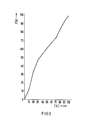
- the guide groove can be varied and, for example for the heating characteristic, a progressive course of movement according to the characteristic according to Fig. 3 of the transmission element is possible. This and the effect of self-locking are particularly advantageous. Finally, the smaller construction depth is favorable in terms of space. The use of a smaller number of components - saving on an intermediate lever - especially reduces the assembly costs.
- the base body and the other components of the control unit can be made of any plastic.
- Acrylonitrile-butadiene-styrene copolymers ABS
- PA 6-GV glass fiber reinforced polyamides
- PPO polyphenylene oxide
- POM polyoxymethylene
- PP-GV glass fiber reinforced polypropylene
- Figure 1 shows a control device, in plan view consisting of a base body 6 made of plastic, in the guideway 4 of the actuating lever 1 is guided.
- the actuating lever 2 actuated by the actuating lever has a guide pin 5 which is guided in the guide groove 3.
- the Bowden cable 7 is suspended in the adjusting lever 2 and fastened to the basic body 2 by means of the Bowden cable clip 8 rotatably mounted on the basic body 2.
- a is the angle between the Bowden cable 7 and the actuating lever 2.
- ⁇ is the angle between the guide groove 3 and the actuating lever 1.
- FIG. 2 shows in section a Bowden cable clip 8 which is snapped into the base body 6. 7 is again the Bowden cable.
Landscapes
- Physics & Mathematics (AREA)
- Engineering & Computer Science (AREA)
- Thermal Sciences (AREA)
- Mechanical Engineering (AREA)
- General Physics & Mathematics (AREA)
- Automation & Control Theory (AREA)
- Air-Conditioning For Vehicles (AREA)
- Mechanical Control Devices (AREA)
- Flexible Shafts (AREA)
- Air Conditioning Control Device (AREA)
- Direct Air Heating By Heater Or Combustion Gas (AREA)
Abstract
Description
- Die Erfindung betrifft ein Steuergerät für Heizungs-, Klima- und Lüftungsanlagen in Kraftfahrzeugen bestehend aus Kunststoff, mindestens einem Stellhebel und mindestens einem Betätigungshebel. Derartige Vorrichtungen befinden sich überwiegend am Armaturenbrett von Kraftfahrzeugen.
- In Kraftfahrzeugen kann gemäß einer bekannten Vorrichtung (DE-PS 1655102) eine Regeleinrichtung mittels eines Bowdenzuges betätigt werden, wobei für die zwangsläufige Übertragung der Stellbewegung zwischen dem Betätigungshebel und dem Befestigungspunkt des Bowdenzuges eine Hebelvorrichtung vorgesehen ist, die zwei Teile enthält, nämlich ein um eine feste Achse schwenkbares Teil, das über eine Gleit- und gegebenenfalls Schwenkverbindung mit einem weiteren Teil verbunden ist. Der Befestigungspunkt des Bowdenzuges ist an einem der beiden Teile vorgesehen. Der Betätigungshebel ist an dem anderen Teil angebracht. Es sind die Betätigungskräfte entweder nicht über den gesamten Hub gleichmäßig und demzufolge keine gleichmäßig leichte Bewegung des Stellhebels möglich oder es beruht der Übergang vom Stell- zum Betätigungshebel auf dem Prinzip der Linienführung, woraus ein erhöhter Verschleiß resultiert.
- Gemäß der DE-OS 2852452 ist der Stellhebel, der in Lüftungsanlagen von in Kraftfahrzeugen angebracht ist, beidseitig zwischen sich in Stellrichtung erstreckenden Führungsflächen geführt. Die technische Gestaltung der Vorrichtung ist sehr aufwendig und besteht aus vielen Einzelteilen.
- Gemäß einer weiteren bekannten Ausführung, DE-OS 3206288, ist zwischen dem (den) Stellhebel(n) und dem (den) Betätigungshebel(n) ein drehbar gelagerter Zwischenhebel angeordnet, wodurch die kreisförmige Bewegung des Stellhebels und die geradlinige oder leicht gekrümmte Bewegung des (der) Betätigungshebel kombiniert werden. Es entsteht eine einwandfreie Parallelführung des (der) Betätigungshebel in der Führungsschiene. In der Strecklage des Zwischenhebels kann eine Selbstverriegelung der Kinematik erreicht werden.
- Der Erfindung liegt die Aufgabe zugrunde, den Weg eines Betätigungshebels in den Weg eines Übertragungselementes umzusetzen, das ein Stellglied, beispielsweise eine Luftklappe, oder einen elektrischen Widerstand ansteuert. Dabei soll die Selbstverriegelung der Gesamtkinematik mindestens in einer Endstellung beim Wegfall des Zwischenhebels erreicht werden. Der Stellhebel soll nicht in einer festen Achse gelagert sein. Der Wegeverlauf des Übertragungselementes soll gegenüber dem Weg des Betätigungshebels je nach Anforderung variiert werden können.
- Diese Aufgabe wird dadurch gelöst, daß erfindungsgemäß in den drehbar am Betätigungshebel gelagerten Stellhebel ein Führungsbolzen integriert und ein Bowdenzug eingehängt sind und daß der Führungsbolzen in einer Führungsnut geführt wird. Die Führungsnut kann in den Grundkörper integnert sein. Der Verlauf der Führungsnut ist so ausgelegt, daß die vorgegebenen Stellwege über den Führungsbolzen und das Übertragungselement erfüllt sind.
- Der Bowdenzug kann an einem Bowdenzugklips befestigt sein und an dem Grundkörper drehbar gelagert angebracht sein.
- Mit einer Ausführung gemäß der Erfindung kann die Führungsnut variiert werden und es ist beispielsweise für die Heizungskennlinie ein progressiver Bewegungsverlauf aemäß der Kennlinie nach Fiaur 3 des Übertragungselementes möglich. Dies und der Effekt der Selbstverriegelung sind besonders vorteilhaft. Schließlich ist die kleinere Bautiefe raummäßig günstig. Der Einsatz einer kleineren Anzahl an Bauteilen - Einsparung eines Zwischenhebels - senkt vor allem die Montagekosten.
- Die Selbstverriegelung der Kinematik in mindestens einer Endstellung wird erreicht
- 1. Durch die Abstimmung zwischen dem Bowdenzug und dem Stellhebel. Der Winkel a liegt zwischen 8° - 90°.
- 2. Durch die Abstimmung zwischen dem Stellweghebel und dem Betätigungshebel. Der Winkel β liegt zwischen (10°) - 45°.
- 3. Durch die Abstimmung zwischen der Führungsnut und dem Betätigungshebel. Der Winkel liegt zwischen 0° - 45°.
- Der Grundkörper und die übrigen Bauteile des Steuergerätes können aus einem beliebigen Kunststoff bestehen. Besonders geeignet sind AcrylnitrilButadien-Styrol-Copolymere (ABS), Polyamide glasfaserverstärkt (PA 6-GV), Polyphenylenoxid (PPO), Polyoxymethylen (POM), Polypropylen glasfaserverstärkt (PP-GV).
- Die Erfindung wird anhand der Zeichnung, die ein Ausführungsbeispiel enthält, näher erläutert.
- Figur 1 zeigt ein Steuergerät, in Draufsicht bestehend aus einem Grundkörper 6 aus Kunststoff, in dessen Führungsbahn 4 der Betätigungshebel 1 geführt wird. Der durch den Betätigungshebel betätigte Stellhebel 2 weist einen Führungsbolzen 5 auf, der in der Führungsnut 3 geführt wird. Der Bowdenzug 7 ist in den Stellhebel 2 eingehängt und mittels des am Grundkörper 2 drehbar gelagerten Bowdenzugklipses 8 am Grundkörper 2 befestigt. a ist der Winkel zwischen dem Bowdenzug 7 und dem Stellhebel 2. β ist der Winkel zwischen der Führungsnut 3 und dem Betätigungshebel 1. ist der Winkel zwischen dem Stellhebel 2 und dem Betätigungshebel 1.
- Figur 2 zeigt im Schnitt einen Bowdenzugklips 8, der in den Grundkörper 6 eingerastet ist. Mit 7 ist wiederum der Bowdenzug bezeichnet.
Claims (3)
Priority Applications (1)
| Application Number | Priority Date | Filing Date | Title |
|---|---|---|---|
| AT85112734T ATE39441T1 (de) | 1984-10-23 | 1985-10-08 | Steuergeraet fuer heizungs-, klima- und lueftungsanlagen in kraftfahrzeugen. |
Applications Claiming Priority (2)
| Application Number | Priority Date | Filing Date | Title |
|---|---|---|---|
| DE3438833 | 1984-10-23 | ||
| DE3438833 | 1984-10-23 |
Publications (2)
| Publication Number | Publication Date |
|---|---|
| EP0183019A1 true EP0183019A1 (de) | 1986-06-04 |
| EP0183019B1 EP0183019B1 (de) | 1988-12-28 |
Family
ID=6248593
Family Applications (1)
| Application Number | Title | Priority Date | Filing Date |
|---|---|---|---|
| EP85112734A Expired EP0183019B1 (de) | 1984-10-23 | 1985-10-08 | Steuergerät für Heizungs-, Klima- und Lüftungsanlagen in Kraftfahrzeugen |
Country Status (6)
| Country | Link |
|---|---|
| US (1) | US4656880A (de) |
| EP (1) | EP0183019B1 (de) |
| AT (1) | ATE39441T1 (de) |
| DE (1) | DE3566984D1 (de) |
| ES (1) | ES296279Y (de) |
| PT (1) | PT81350B (de) |
Cited By (3)
| Publication number | Priority date | Publication date | Assignee | Title |
|---|---|---|---|---|
| EP0433245A3 (en) * | 1989-11-16 | 1991-08-07 | Borletti Climatizzazione S.R.L. | A device for operating movable parts of motor-vehicle air-conditioning systems |
| FR2788087A1 (fr) * | 1998-12-30 | 2000-07-07 | Valeo Climatisation | Dispositif de transmission de mouvement a cable coulissant |
| WO2014180457A1 (de) * | 2013-05-10 | 2014-11-13 | Kiekert Aktiengesellschaft | Befestigungselement zur anbindung von übertragungsmitteln an ein hebelelement |
Families Citing this family (5)
| Publication number | Priority date | Publication date | Assignee | Title |
|---|---|---|---|---|
| US4947704A (en) * | 1989-08-24 | 1990-08-14 | Babcock Industries Inc. | Snap on strand assembly |
| US5154093A (en) * | 1990-06-08 | 1992-10-13 | Ford Motor Company | Adjustable cable end fitting |
| USD430477S (en) * | 1999-09-17 | 2000-09-05 | Siemens Energy & Automation, Inc. | Handle grip |
| US6262382B1 (en) | 1999-09-28 | 2001-07-17 | Siemens Energy & Automation, Inc. | Extended keyhole slot |
| US6655197B2 (en) | 2001-07-23 | 2003-12-02 | Sonnax Industries, Inc. | Automatic transmission fluid characteristic monitoring system employed for repair/maintenance and during operation of a land motor vehicle |
Citations (4)
| Publication number | Priority date | Publication date | Assignee | Title |
|---|---|---|---|---|
| DE1605896A1 (de) * | 1967-06-23 | 1970-07-16 | Audi Nsu Auto Union Ag | Betaetigungsvorrichtung eines Heizungs- und Belueftungsgeraetes fuer den Innenraum eines Kraftwagens |
| EP0087084A2 (de) * | 1982-02-22 | 1983-08-31 | Siemens Aktiengesellschaft | Steuergerät mit beleuchteten Betätigungsknöpfen für Heizungs-,Klima- und Lüftungsanlagen in Kraftfahrzeugen |
| EP0097876A1 (de) * | 1982-06-28 | 1984-01-11 | Siemens Aktiengesellschaft | Steuergerät für Heizungs- und Lüftungsanlagen in Kraftfahrzeugen |
| EP0097878A2 (de) * | 1982-06-28 | 1984-01-11 | Siemens Aktiengesellschaft | Steuergerät für Heizungs- und Lüftungsanlagen in Kraftfahrzeugen |
Family Cites Families (5)
| Publication number | Priority date | Publication date | Assignee | Title |
|---|---|---|---|---|
| US2933942A (en) * | 1955-09-16 | 1960-04-26 | Gen Motors Corp | Unitary mechanisms for sequential control |
| FR209M (fr) * | 1960-08-18 | 1961-02-20 | Rhone Poulenc Sa | Nouveaux dérivés de la dibenzazépine. |
| US3342081A (en) * | 1965-07-09 | 1967-09-19 | Telefiex Inc | Remote control assembly |
| DE2852452A1 (de) * | 1978-12-04 | 1980-06-19 | Kammerer Gmbh M | Schieberegler fuer lueftungsanlagen in kraftfahrzeugen |
| US4428251A (en) * | 1982-04-14 | 1984-01-31 | General Motors Corporation | Automatic adjustment mechanism for a cable drive |
-
1985
- 1985-09-19 US US06/777,596 patent/US4656880A/en not_active Expired - Fee Related
- 1985-10-08 EP EP85112734A patent/EP0183019B1/de not_active Expired
- 1985-10-08 DE DE8585112734T patent/DE3566984D1/de not_active Expired
- 1985-10-08 AT AT85112734T patent/ATE39441T1/de not_active IP Right Cessation
- 1985-10-22 PT PT81350A patent/PT81350B/de unknown
- 1985-10-22 ES ES1985296279U patent/ES296279Y/es not_active Expired
Patent Citations (4)
| Publication number | Priority date | Publication date | Assignee | Title |
|---|---|---|---|---|
| DE1605896A1 (de) * | 1967-06-23 | 1970-07-16 | Audi Nsu Auto Union Ag | Betaetigungsvorrichtung eines Heizungs- und Belueftungsgeraetes fuer den Innenraum eines Kraftwagens |
| EP0087084A2 (de) * | 1982-02-22 | 1983-08-31 | Siemens Aktiengesellschaft | Steuergerät mit beleuchteten Betätigungsknöpfen für Heizungs-,Klima- und Lüftungsanlagen in Kraftfahrzeugen |
| EP0097876A1 (de) * | 1982-06-28 | 1984-01-11 | Siemens Aktiengesellschaft | Steuergerät für Heizungs- und Lüftungsanlagen in Kraftfahrzeugen |
| EP0097878A2 (de) * | 1982-06-28 | 1984-01-11 | Siemens Aktiengesellschaft | Steuergerät für Heizungs- und Lüftungsanlagen in Kraftfahrzeugen |
Cited By (4)
| Publication number | Priority date | Publication date | Assignee | Title |
|---|---|---|---|---|
| EP0433245A3 (en) * | 1989-11-16 | 1991-08-07 | Borletti Climatizzazione S.R.L. | A device for operating movable parts of motor-vehicle air-conditioning systems |
| FR2788087A1 (fr) * | 1998-12-30 | 2000-07-07 | Valeo Climatisation | Dispositif de transmission de mouvement a cable coulissant |
| WO2014180457A1 (de) * | 2013-05-10 | 2014-11-13 | Kiekert Aktiengesellschaft | Befestigungselement zur anbindung von übertragungsmitteln an ein hebelelement |
| US10619665B2 (en) | 2013-05-10 | 2020-04-14 | Kiekert Aktiengesellschaft | Fastening element for connecting transmission means to a lever element |
Also Published As
| Publication number | Publication date |
|---|---|
| PT81350A (de) | 1985-11-01 |
| EP0183019B1 (de) | 1988-12-28 |
| ATE39441T1 (de) | 1989-01-15 |
| ES296279U (es) | 1987-08-16 |
| PT81350B (de) | 1987-01-26 |
| DE3566984D1 (en) | 1989-02-02 |
| ES296279Y (es) | 1988-03-16 |
| US4656880A (en) | 1987-04-14 |
Similar Documents
| Publication | Publication Date | Title |
|---|---|---|
| EP0337382A1 (de) | Belüftungsanlage für ein Kraftfahrzeug | |
| EP0183019A1 (de) | Steuergerät für Heizungs-, Klima- und Lüftungsanlagen in Kraftfahrzeugen | |
| DE3908612C2 (de) | ||
| DE2557077B2 (de) | Bedienungsvorrichtung fuer ein uebertragungsorgan in kraftfahrzeugen | |
| EP0819573B1 (de) | Kopfstützen-Arretiereinrichtung | |
| EP0033761A1 (de) | Gaspedalbewegungsdämpfer | |
| DE19706677C2 (de) | Bedienelement | |
| DE3202355A1 (de) | Luftauslassduese von belueftungsanlagen fuer kraftfahrzeuginnenraeume | |
| EP0087084B1 (de) | Steuergerät mit beleuchteten Betätigungsknöpfen für Heizungs-,Klima- und Lüftungsanlagen in Kraftfahrzeugen | |
| EP0097876B1 (de) | Steuergerät für Heizungs- und Lüftungsanlagen in Kraftfahrzeugen | |
| EP1082557A1 (de) | Schaltvorrichtung für kraftfahrzeuge | |
| DE3332984A1 (de) | Anordnung von stellorganen, insbesondere fuer vorrichtungen zur beheizung und belueftung von fahrerkabinen, fahrgastraeumen od.dgl. in nutzfahrzeugen | |
| DE8431121U1 (de) | Steuergerät für Heizungs-, Klima- und Lüftungsanlagen in Kraftfahrzeugen | |
| DE19724684C2 (de) | Bestätigungsvorrichtung | |
| EP0097878A2 (de) | Steuergerät für Heizungs- und Lüftungsanlagen in Kraftfahrzeugen | |
| EP0178455B1 (de) | Steuergerät für Heizungs-, Klima- und Lüftungsanlagen in Kraftfahrzeugen | |
| DE3821541C2 (de) | Vorrichtung zum Belüften und/oder Heizen des Innenraums von Kraftfahrzeugen | |
| DE8218485U1 (de) | Steuergerät für Heizungs- und Lüftungsanlagen in Kraftfahrzeugen | |
| DE2514886C3 (de) | Drehschieber für die Innenraumbeheizung von Kraftfahrzeugen | |
| DE8218443U1 (de) | Steuergerät für Heizungs- und Lüftungsanlagen in Kraftfahrzeugen | |
| DE102018118234A1 (de) | Mitnehmer für einen Luftausströmer und Luftausströmer | |
| EP2436947A2 (de) | Einrichtung zur erzeugung einer bedienkraft und der dämpfung der bewegung | |
| DE8204853U1 (de) | Steuergerät mit beleuchteten Betätigungsknöpfen für Heizungs-, Klima- und Lüftungsanlagen in Kraftfahrzeugen | |
| EP0751020A1 (de) | Bodenzugverstellvorrichtung, insbesondere für Kraftfahrzeugheizung und -lüftung | |
| DE102024111931A1 (de) | Laterale Kfz-Luftleitanordnung |
Legal Events
| Date | Code | Title | Description |
|---|---|---|---|
| PUAI | Public reference made under article 153(3) epc to a published international application that has entered the european phase |
Free format text: ORIGINAL CODE: 0009012 |
|
| AK | Designated contracting states |
Kind code of ref document: A1 Designated state(s): AT BE DE FR GB IT NL SE |
|
| 17P | Request for examination filed |
Effective date: 19860626 |
|
| 17Q | First examination report despatched |
Effective date: 19861219 |
|
| GRAA | (expected) grant |
Free format text: ORIGINAL CODE: 0009210 |
|
| AK | Designated contracting states |
Kind code of ref document: B1 Designated state(s): AT BE DE FR GB IT NL SE |
|
| REF | Corresponds to: |
Ref document number: 39441 Country of ref document: AT Date of ref document: 19890115 Kind code of ref document: T |
|
| REF | Corresponds to: |
Ref document number: 3566984 Country of ref document: DE Date of ref document: 19890202 |
|
| ET | Fr: translation filed | ||
| ITF | It: translation for a ep patent filed | ||
| PGFP | Annual fee paid to national office [announced via postgrant information from national office to epo] |
Ref country code: AT Payment date: 19890929 Year of fee payment: 5 |
|
| PGFP | Annual fee paid to national office [announced via postgrant information from national office to epo] |
Ref country code: NL Payment date: 19891031 Year of fee payment: 5 |
|
| PGFP | Annual fee paid to national office [announced via postgrant information from national office to epo] |
Ref country code: BE Payment date: 19891103 Year of fee payment: 5 |
|
| PLBE | No opposition filed within time limit |
Free format text: ORIGINAL CODE: 0009261 |
|
| STAA | Information on the status of an ep patent application or granted ep patent |
Free format text: STATUS: NO OPPOSITION FILED WITHIN TIME LIMIT |
|
| 26N | No opposition filed | ||
| PG25 | Lapsed in a contracting state [announced via postgrant information from national office to epo] |
Ref country code: AT Effective date: 19901008 |
|
| PG25 | Lapsed in a contracting state [announced via postgrant information from national office to epo] |
Ref country code: BE Effective date: 19901031 |
|
| BERE | Be: lapsed |
Owner name: SIEMENS A.G. BERLIN UND MUNCHEN Effective date: 19901031 |
|
| PG25 | Lapsed in a contracting state [announced via postgrant information from national office to epo] |
Ref country code: NL Effective date: 19910501 |
|
| NLV4 | Nl: lapsed or anulled due to non-payment of the annual fee | ||
| PGFP | Annual fee paid to national office [announced via postgrant information from national office to epo] |
Ref country code: SE Payment date: 19911017 Year of fee payment: 7 |
|
| ITTA | It: last paid annual fee | ||
| PG25 | Lapsed in a contracting state [announced via postgrant information from national office to epo] |
Ref country code: SE Effective date: 19921009 |
|
| PGFP | Annual fee paid to national office [announced via postgrant information from national office to epo] |
Ref country code: GB Payment date: 19930913 Year of fee payment: 9 |
|
| PGFP | Annual fee paid to national office [announced via postgrant information from national office to epo] |
Ref country code: FR Payment date: 19931018 Year of fee payment: 9 |
|
| PGFP | Annual fee paid to national office [announced via postgrant information from national office to epo] |
Ref country code: DE Payment date: 19931216 Year of fee payment: 9 |
|
| PG25 | Lapsed in a contracting state [announced via postgrant information from national office to epo] |
Ref country code: GB Effective date: 19941008 |
|
| EUG | Se: european patent has lapsed |
Ref document number: 85112734.0 Effective date: 19930510 |
|
| GBPC | Gb: european patent ceased through non-payment of renewal fee |
Effective date: 19941008 |
|
| PG25 | Lapsed in a contracting state [announced via postgrant information from national office to epo] |
Ref country code: FR Effective date: 19950630 |
|
| PG25 | Lapsed in a contracting state [announced via postgrant information from national office to epo] |
Ref country code: DE Effective date: 19950701 |
|
| REG | Reference to a national code |
Ref country code: FR Ref legal event code: ST |