EP0182721A2 - Bandkassettenbehälter - Google Patents
Bandkassettenbehälter Download PDFInfo
- Publication number
- EP0182721A2 EP0182721A2 EP85402249A EP85402249A EP0182721A2 EP 0182721 A2 EP0182721 A2 EP 0182721A2 EP 85402249 A EP85402249 A EP 85402249A EP 85402249 A EP85402249 A EP 85402249A EP 0182721 A2 EP0182721 A2 EP 0182721A2
- Authority
- EP
- European Patent Office
- Prior art keywords
- case
- projections
- wall members
- tape cassette
- cassette
- Prior art date
- Legal status (The legal status is an assumption and is not a legal conclusion. Google has not performed a legal analysis and makes no representation as to the accuracy of the status listed.)
- Withdrawn
Links
- 239000000463 material Substances 0.000 description 9
- 229920003023 plastic Polymers 0.000 description 4
- 230000015572 biosynthetic process Effects 0.000 description 3
- 238000000034 method Methods 0.000 description 3
- 230000004048 modification Effects 0.000 description 3
- 238000012986 modification Methods 0.000 description 3
- 239000004033 plastic Substances 0.000 description 3
- 239000002985 plastic film Substances 0.000 description 3
- 239000004743 Polypropylene Substances 0.000 description 2
- -1 polypropylene Polymers 0.000 description 2
- 229920001155 polypropylene Polymers 0.000 description 2
- 239000002699 waste material Substances 0.000 description 2
- 238000003466 welding Methods 0.000 description 2
- 239000000853 adhesive Substances 0.000 description 1
- 230000001070 adhesive effect Effects 0.000 description 1
Images


Classifications
-
- G—PHYSICS
- G11—INFORMATION STORAGE
- G11B—INFORMATION STORAGE BASED ON RELATIVE MOVEMENT BETWEEN RECORD CARRIER AND TRANSDUCER
- G11B23/00—Record carriers not specific to the method of recording or reproducing; Accessories, e.g. containers, specially adapted for co-operation with the recording or reproducing apparatus ; Intermediate mediums; Apparatus or processes specially adapted for their manufacture
- G11B23/02—Containers; Storing means both adapted to cooperate with the recording or reproducing means
- G11B23/023—Containers for magazines or cassettes
- G11B23/0233—Containers for a single cassette
Definitions
- the present invention is directed to a case for receiving a tape cassette such as a video cassette.
- a case or a box for a video cassette has been produced by forming a blank from a sheet of cardboard-like material or plastic material. The blank is then folded and joined together to form a rectangular prism or box having an opening at one edge through which the cassette is inserted into the case.
- An example of such a known case or cassette sleeve is disclosed in United Kingdom Patent 2, 083, 937.
- the smooth outer finish may become slippery when grasped by a person handling the cassette and case.
- Another problem is that if the cassette has a tight fit within the case, a removal of the cassette can be hampered due to a suction being created in the base of the case as the cassette is being removed therefrom.
- the present invention is directed to an improved case or cassette sleeve which has an increased resistance to the formation of visible scratches and has surfaces with an increased friction.
- the present invention is directed to a case for a tape cassette, said case having five wall members arranged to form a rectangular prism with an opening on one side thereof through which a tape cassette is inserted, said case on at least one surface of each wall member having a plurality of line-like projections extending parallel to each other.
- the inner surface of the wall members have the projections, this will greatly reduce problems with unsightly scratches being formed on the inner surface due to inserting and removing the cassette from the case. If only the outer surfaces are provided with the projections, this will greatly increase the friction for these outer surfaces to enable easy grasping of the case and also easy stacking of the cases without slippage.
- the case will have a first and second set of the line-like projections with the line-like projections of the first set extending in a first direction and the line-like projections of the second set extending in a second direction at an angle to the first direction.
- at least one of the first and second sets is on an outer surface of each wall member of the case. It is possible that both the first and second sets are provided on the outer surface although the first set could be provided en the outer surface and the second set is provided on the inner surface.
- the projections on each surface prevent or limit the formation of unsightly scratches on that surface.
- the projections increase the surface friction to enable easy grasping of the case and present the case from sliding when piled with other cases. With the first and second directions extending at an angle to each other, this will improve the mechanical strength of the sheet-like material forming the wall members of the case and therefore improve the structural rigidity of the case to prevent deformation from the application of outside forces or from an application of heat.
- the principles of the present invention are particularly useful when incorporated in a case or cassette sleeve C which is illustrated in FIG.1 in an exploded perspective view with a label sheet S and a tape cassette T.
- the case C is a rectangular box or prism having five side wall members 10, 11, 12 and 13 (FIG.1) and 14 (see FIG. 6) which are formed into a rectangular box or rectangular prism having one edge or side missing to form an opening 5.
- the edges of the wall members 10 and 13 may have a cut-out portion as illustrated.
- the cassette T which is illustrated as being a video cassette is inserted through the opening 5 into the case C.
- a label sheet S may be provided to give information concerning the cassette such as the running time, the contents, etc.
- the sleeve S has three panels with one panel 20 corresponding to the wall member 13 of the case, a panel 21 which corresponds to the side wall 14 (FIG.6) and a short tab or panel 22, which would cover only a small portion of the inner surface of the wall member 10.
- the cassette sleeve or case C as explained thus far has the structure which is presently known.
- the improvements in the cassette sleeve or case C are the provisions of a plurality of line-like projections 2 on the outer surface of each wall member 10-14 and a second set of projections 3 provided on the inner surface of each wall member 10-14.
- the line-like projections 2 extend parallel to each other in a first direction while the line-like projections 3 extend parallel to each other in a second direction at right angles to the first direction of the projections 2.
- projections 2 and 3 have a height that lies in the range of 10 to 40Pm and a width which is also in the same range. As illustrated, they have substantially a square cross-section with the spacing between the projections being in the range of 1 to 5 mm.
- the wall thickness of the sheet forming the wall members is in the range of 0.5 to 1 P m and the sheet is preferably formed of a plastic material such as polypropylene.
- FIGS. 3a-3e An example of a process of forming the case or box C is illustrated in FIGS. 3a-3e.
- a first step is to provide a plastic sheet 100 which is made of, for example, polypropylene.
- the sheet 100 is then passed between a pair of rollers each having a plurality of grooves corresponding to the line-like projections to be formed on the sheet.
- the sheet is heated as it is passed through the rollers so that the plurality of projections 2 are formed on one surface of the sheet while a plurality of projections 3 are formed on the opposite surface.
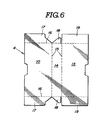
- the sheet with the projections are subjected to a die cutting or punch-cutting to form box blanks with a profile 4 which is best illustrated in FIG.6.
- the box blank 4 is then folded into the case-shape illustrated in FIG. 3d and subsequently the overlapping end flaps are spot-welded at point 6 to complete the formation of the case.
- the spot-welding can be carried out by an ultrasonic spot-welding process.
- the blank as best illustrated in FIG.6 with the excess material stripped therefrom, has panels 10, 14 and 13 which are separated by fold lines or creases 15 and these panels correspond to the wall members.
- panels 10, 14 and 13 are two fold lines or creases 16 which define two end flaps 17 from panel 10, two flaps 18 from panel 14 and two flaps 19 from panel 13.
- the flaps 17, 18 and 19 are folded with the flap 19 being on the outer surface to form the end wall members 11 and 12 of the case or cassette sleeve C.
- the fold lines 15 and 16 are formed at the time of cutting the blank and facilitate folding the various panels to form the case C.
- the projections are provided on each surface of each of the wall members.
- projections 2' and 3' are provided only on one of the surfaces such as the outer surface of each of the wall mebers such as member 10'. It is noted that they could also be provided only on the inner wall surface if this was all that was desired.
- the projections extend basically at right angles to each other and also are at an angle of approximatemy 45° to the edges of each of the wall members such as the wall member 10 or 10'.
- Other arrangements for the projections can be provided.
- a case C" has a set 2" on the outer surface and a set 3" on the inner surface with the sets extending at right angles to each other and also at substantially right angles to the edges of the wall members such as 10" .
- projections 3"' are on the outer surface of each of the wall members while the projections 3"' are on the inner wall surface and these projections extend at an angle other than a right angle to each other and to the edges of the wall members such as members 10"' so that a diamond-shaped pattern is produced.
- a label sheet can be inserted in the casing. It is also possible to apply or print a label on an outer surface of the case such as the label 7 in FIG. 5b.
- This label can be directly printed on the wall member 10"' or be an adhesive label which is fixed onto the outer surface of the wall members.
- the label can contain information concerning the cassette such as the length and/or program recorded thereon.
Landscapes
- Packaging Of Annular Or Rod-Shaped Articles, Wearing Apparel, Cassettes, Or The Like (AREA)
Applications Claiming Priority (2)
| Application Number | Priority Date | Filing Date | Title |
|---|---|---|---|
| JP175974/84U | 1984-11-20 | ||
| JP1984175974U JPS6191569U (de) | 1984-11-20 | 1984-11-20 |
Publications (2)
| Publication Number | Publication Date |
|---|---|
| EP0182721A2 true EP0182721A2 (de) | 1986-05-28 |
| EP0182721A3 EP0182721A3 (de) | 1987-08-12 |
Family
ID=16005499
Family Applications (1)
| Application Number | Title | Priority Date | Filing Date |
|---|---|---|---|
| EP85402249A Withdrawn EP0182721A3 (de) | 1984-11-20 | 1985-11-20 | Bandkassettenbehälter |
Country Status (4)
| Country | Link |
|---|---|
| EP (1) | EP0182721A3 (de) |
| JP (1) | JPS6191569U (de) |
| AU (1) | AU5000385A (de) |
| ES (1) | ES296819Y (de) |
Cited By (7)
| Publication number | Priority date | Publication date | Assignee | Title |
|---|---|---|---|---|
| US4987999A (en) * | 1990-01-22 | 1991-01-29 | Alpha Enterprises, Inc. | Videocassette storage and display sleeve |
| US4988000A (en) * | 1990-02-05 | 1991-01-29 | Alpha Enterprises, Inc. | Videocassette storage and display sleeve |
| EP0441631A1 (de) * | 1990-02-08 | 1991-08-14 | Sony Corporation | Videokassettenbehälter mit harten Kunststoffolien versehenen Flanken |
| EP0446629A2 (de) * | 1990-02-13 | 1991-09-18 | Fuji Photo Film Co., Ltd. | Lagerungsmethode einer Kassette und Indexkarte für Kassettengehäuse |
| US5211287A (en) * | 1990-02-05 | 1993-05-18 | Alpha Enterprises, Inc. | Videocassette storage and display sleeve |
| US6092297A (en) * | 1998-02-27 | 2000-07-25 | Simon; Paul E. | Videocassette time measurement device |
| EP1486977A3 (de) * | 2003-06-11 | 2007-07-18 | FUJIFILM Corporation | Aufbewahrungsbehälter für Bandkassette |
Citations (6)
| Publication number | Priority date | Publication date | Assignee | Title |
|---|---|---|---|---|
| DE2700556A1 (de) * | 1976-07-09 | 1978-01-19 | Mondadori Editore Spa | Schutzgehaeuse fuer ton- und/oder bildtraegerkassetten |
| DE3015747A1 (de) * | 1980-04-24 | 1981-10-29 | IDN Inventions and Development of Novelties AG, Chur | Stapelbarer kunststoffbehaelter fuer standardmagnetbandkassetten |
| EP0054275A1 (de) * | 1980-12-13 | 1982-06-23 | 4P Nicolaus Kempten GmbH | Verfahren und Vorrichtung zum Aufrichten und Versiegeln einer einseitig offenen Falthülle aus Karton |
| US4365711A (en) * | 1979-01-05 | 1982-12-28 | Long Jerry M | Video cassette storage and shipping container apparatus |
| DE3200306C1 (de) * | 1982-01-08 | 1983-07-28 | Druckhaus Maack KG, 5880 Lüdenscheid | Schutzhülle aus Karton für Videocassetten |
| EP0116315A1 (de) * | 1983-01-19 | 1984-08-22 | Hitachi Maxell Ltd. | Kassettenbehälter |
-
1984
- 1984-11-20 JP JP1984175974U patent/JPS6191569U/ja active Pending
-
1985
- 1985-11-18 AU AU50003/85A patent/AU5000385A/en not_active Abandoned
- 1985-11-19 ES ES1985296819U patent/ES296819Y/es not_active Expired
- 1985-11-20 EP EP85402249A patent/EP0182721A3/de not_active Withdrawn
Patent Citations (6)
| Publication number | Priority date | Publication date | Assignee | Title |
|---|---|---|---|---|
| DE2700556A1 (de) * | 1976-07-09 | 1978-01-19 | Mondadori Editore Spa | Schutzgehaeuse fuer ton- und/oder bildtraegerkassetten |
| US4365711A (en) * | 1979-01-05 | 1982-12-28 | Long Jerry M | Video cassette storage and shipping container apparatus |
| DE3015747A1 (de) * | 1980-04-24 | 1981-10-29 | IDN Inventions and Development of Novelties AG, Chur | Stapelbarer kunststoffbehaelter fuer standardmagnetbandkassetten |
| EP0054275A1 (de) * | 1980-12-13 | 1982-06-23 | 4P Nicolaus Kempten GmbH | Verfahren und Vorrichtung zum Aufrichten und Versiegeln einer einseitig offenen Falthülle aus Karton |
| DE3200306C1 (de) * | 1982-01-08 | 1983-07-28 | Druckhaus Maack KG, 5880 Lüdenscheid | Schutzhülle aus Karton für Videocassetten |
| EP0116315A1 (de) * | 1983-01-19 | 1984-08-22 | Hitachi Maxell Ltd. | Kassettenbehälter |
Cited By (11)
| Publication number | Priority date | Publication date | Assignee | Title |
|---|---|---|---|---|
| US4987999A (en) * | 1990-01-22 | 1991-01-29 | Alpha Enterprises, Inc. | Videocassette storage and display sleeve |
| US4988000A (en) * | 1990-02-05 | 1991-01-29 | Alpha Enterprises, Inc. | Videocassette storage and display sleeve |
| US5211287A (en) * | 1990-02-05 | 1993-05-18 | Alpha Enterprises, Inc. | Videocassette storage and display sleeve |
| EP0441631A1 (de) * | 1990-02-08 | 1991-08-14 | Sony Corporation | Videokassettenbehälter mit harten Kunststoffolien versehenen Flanken |
| US5415288A (en) * | 1990-02-08 | 1995-05-16 | Sony Corporation | Video cassette case having hard plastic sheets on flat surfaces thereof |
| EP0446629A2 (de) * | 1990-02-13 | 1991-09-18 | Fuji Photo Film Co., Ltd. | Lagerungsmethode einer Kassette und Indexkarte für Kassettengehäuse |
| EP0446629A3 (en) * | 1990-02-13 | 1991-10-23 | Fuji Photo Film Co., Ltd. | Cassette accommodating method and index card for cassette case |
| US5127673A (en) * | 1990-02-13 | 1992-07-07 | Fuji Photo Film Co., Ltd. | Cassette accommodating method and index card for cassette case |
| US6092297A (en) * | 1998-02-27 | 2000-07-25 | Simon; Paul E. | Videocassette time measurement device |
| EP1486977A3 (de) * | 2003-06-11 | 2007-07-18 | FUJIFILM Corporation | Aufbewahrungsbehälter für Bandkassette |
| US7316314B2 (en) | 2003-06-11 | 2008-01-08 | Fujifilm Corporation | Tape cassette storing case with stacking ribs |
Also Published As
| Publication number | Publication date |
|---|---|
| ES296819Y (es) | 1988-09-16 |
| AU5000385A (en) | 1986-05-29 |
| JPS6191569U (de) | 1986-06-13 |
| EP0182721A3 (de) | 1987-08-12 |
| ES296819U (es) | 1988-01-16 |
Similar Documents
| Publication | Publication Date | Title |
|---|---|---|
| WO1984000019A1 (en) | Cover folders | |
| US4787553A (en) | Corner fastening device | |
| GB2156303A (en) | A packing for a stack of sheets | |
| US20220274733A1 (en) | Storage box blank | |
| US4571867A (en) | Information organizing device | |
| EP0182721A2 (de) | Bandkassettenbehälter | |
| EP1380512B1 (de) | Faltschachtel mit Tasche für Beipackzettel und Zuschnitt dafür | |
| US5997207A (en) | Sheet assembly with an optional pocket | |
| EP1386845A1 (de) | Leicht auszurichtende Schachtel mit Tasche für einen Beipackzettel | |
| EP1219542A1 (de) | Verpackung bestehend aus einer Tasche mit einem Beipackzettel | |
| US4727988A (en) | Folded envelope and blank for forming same | |
| US5112290A (en) | Pop-out slide and method of making same | |
| JP5928889B2 (ja) | 包装用箱 | |
| EP0270343A1 (de) | Eckverbindung | |
| EP1378455A1 (de) | Schachtel mit Tasche für Beipackzettel | |
| US5570782A (en) | Disk cartridge case | |
| JP2001130543A (ja) | 曲面カートン | |
| US5901875A (en) | Separator for use in packets of papers | |
| US5088220A (en) | Pop-out slide | |
| EP0450216A1 (de) | Aktendeckel | |
| JP3381552B2 (ja) | ティッシュペーパー用ボックス、およびその折畳方法 | |
| JP4011981B2 (ja) | スリット付きサンプルホルダー | |
| US5743400A (en) | Carrier and/or connector for a series of packages | |
| US5415279A (en) | Sleeving device, kit, and method | |
| EP4438510A1 (de) | Schachtel zum verpacken von kuchen und feingebäck |
Legal Events
| Date | Code | Title | Description |
|---|---|---|---|
| PUAI | Public reference made under article 153(3) epc to a published international application that has entered the european phase |
Free format text: ORIGINAL CODE: 0009012 |
|
| AK | Designated contracting states |
Kind code of ref document: A2 Designated state(s): AT BE DE FR GB IT NL |
|
| PUAL | Search report despatched |
Free format text: ORIGINAL CODE: 0009013 |
|
| AK | Designated contracting states |
Kind code of ref document: A3 Designated state(s): AT BE DE FR GB IT NL |
|
| STAA | Information on the status of an ep patent application or granted ep patent |
Free format text: STATUS: THE APPLICATION IS DEEMED TO BE WITHDRAWN |
|
| 18D | Application deemed to be withdrawn |
Effective date: 19880215 |
|
| RIN1 | Information on inventor provided before grant (corrected) |
Inventor name: SASAKI, SHIN Inventor name: SASAKI, KOJI Inventor name: KAWASHIMA, NORIYASU |