EP0182638A1 - Système pour traiter des feuilles de verre y compris appareil de transport surélevé - Google Patents
Système pour traiter des feuilles de verre y compris appareil de transport surélevé Download PDFInfo
- Publication number
- EP0182638A1 EP0182638A1 EP85308365A EP85308365A EP0182638A1 EP 0182638 A1 EP0182638 A1 EP 0182638A1 EP 85308365 A EP85308365 A EP 85308365A EP 85308365 A EP85308365 A EP 85308365A EP 0182638 A1 EP0182638 A1 EP 0182638A1
- Authority
- EP
- European Patent Office
- Prior art keywords
- glass sheet
- platen
- conveyor
- heated
- holes
- Prior art date
- Legal status (The legal status is an assumption and is not a legal conclusion. Google has not performed a legal analysis and makes no representation as to the accuracy of the status listed.)
- Granted
Links
Images


Classifications
-
- C—CHEMISTRY; METALLURGY
- C03—GLASS; MINERAL OR SLAG WOOL
- C03B—MANUFACTURE, SHAPING, OR SUPPLEMENTARY PROCESSES
- C03B23/00—Re-forming shaped glass
- C03B23/02—Re-forming glass sheets
- C03B23/023—Re-forming glass sheets by bending
-
- C—CHEMISTRY; METALLURGY
- C03—GLASS; MINERAL OR SLAG WOOL
- C03B—MANUFACTURE, SHAPING, OR SUPPLEMENTARY PROCESSES
- C03B35/00—Transporting of glass products during their manufacture, e.g. hot glass lenses, prisms
- C03B35/14—Transporting hot glass sheets or ribbons, e.g. by heat-resistant conveyor belts or bands
- C03B35/145—Transporting hot glass sheets or ribbons, e.g. by heat-resistant conveyor belts or bands by top-side transfer or supporting devices, e.g. lifting or conveying using suction
-
- C—CHEMISTRY; METALLURGY
- C03—GLASS; MINERAL OR SLAG WOOL
- C03B—MANUFACTURE, SHAPING, OR SUPPLEMENTARY PROCESSES
- C03B23/00—Re-forming shaped glass
- C03B23/02—Re-forming glass sheets
- C03B23/023—Re-forming glass sheets by bending
- C03B23/035—Re-forming glass sheets by bending using a gas cushion or by changing gas pressure, e.g. by applying vacuum or blowing for supporting the glass while bending
- C03B23/0352—Re-forming glass sheets by bending using a gas cushion or by changing gas pressure, e.g. by applying vacuum or blowing for supporting the glass while bending by suction or blowing out for providing the deformation force to bend the glass sheet
-
- C—CHEMISTRY; METALLURGY
- C03—GLASS; MINERAL OR SLAG WOOL
- C03B—MANUFACTURE, SHAPING, OR SUPPLEMENTARY PROCESSES
- C03B35/00—Transporting of glass products during their manufacture, e.g. hot glass lenses, prisms
- C03B35/14—Transporting hot glass sheets or ribbons, e.g. by heat-resistant conveyor belts or bands
- C03B35/145—Transporting hot glass sheets or ribbons, e.g. by heat-resistant conveyor belts or bands by top-side transfer or supporting devices, e.g. lifting or conveying using suction
- C03B35/147—Transporting hot glass sheets or ribbons, e.g. by heat-resistant conveyor belts or bands by top-side transfer or supporting devices, e.g. lifting or conveying using suction of the non-contact type
-
- C—CHEMISTRY; METALLURGY
- C03—GLASS; MINERAL OR SLAG WOOL
- C03B—MANUFACTURE, SHAPING, OR SUPPLEMENTARY PROCESSES
- C03B2225/00—Transporting hot glass sheets during their manufacture
- C03B2225/02—Means for positioning, aligning or orientating the sheets during their travel, e.g. stops
Definitions
- This invention relates to glass sheet processing systems and has particular utility in forming heated glass sheets as well as loading glass sheets for processing and conveying glass sheets.
- United States Patent 3,223,443 of George W. Misson discloses a method and apparatus for handling a flat or curved heated glass sheet without physical contact between the glass sheet and a downwardly facing support bed.
- the apparatus of the Misson patent is merely disclosed as supporting a glass sheet without any disclosure of specific utility in any glass sheet processing operation. Only relatively small glass sheet samples, e.g. 4 inches square, were supported by the Misson apparatus after being placed in position by hand which clearly indicates the apparatus was merely experimental without any industrial application.
- Misson patent apparatus includes inverted cup shaped modules that are spaced from each other to establish pressure and exhaust zones adjacent the top surface of the glass sheet to be supported. This establishes flows of gas to and from the zones directly above the glass sheet at a location between the glass sheet and the support bed. Control of the rates at which the gas is emitted and exhausted differentially establishes a net pressure directly above the glass sheet that is less than the ambient pressure by-an-amount equal to the weight of the sheet.
- the support bed supports either unheated glass sheets or glass sheets which have been preheated to a deformation temperature. The glass sheet may be initially supported beneath the bed on a flat, uniform preheated surface. Thereafter, the physical support for the glass sheet is removed.
- Misson patent apparatus includes a support bed having a porous bottom plate through which gas under pressure is supplied. Tubes that extend through the porous plate provide for the withdrawal of gas to reduce the pressure above the glass sheet.
- United States Patent 4,282,026 of Harold A. McMaster, Norman C. Nitschke, and John S. Nitschke discloses apparatus for bending glass sheets wherein a heated glass sheet is received from a horizontal conveyor by a downwardly facing surface of a vacuum holder and is thereafter deposited by the holder onto a curved mold on which bending of the heated glass sheet takes place.
- a differential gas pressure preferably provided by a vacuum drawn through holes at the downwardly facing surface secures the glass sheet to the holder as it is moved from the conveyor to the bending mold.
- a sheet-like cover is provided on the surface and has a porous construction, such as is provided by matted silica fibers, in order to distribute the vacuum and prevent marring and scratching of the heated glass sheet surface engaged by the holder.
- United States Patent 4,111,676 of Charles H. Mechling et al discloses glass sheet tempering performed on a roller conveyor between upper and lower arrays of nozzles through which quenching gas is supplied.
- upper hold-down rolls are provided in case the quenching gas supplied by the lower nozzles lifts the glass sheet being tempered upwardly off the lower conveyor rolls.
- Driving of the upper hold-down rolls is also provided to perform conveyance of a glass sheet lifted off the conveyor rolls by the quenching gas from the lower nozzles.
- An object of the present invention is to provide improved apparatus for providing topside handling of glass sheets.
- the apparatus includes a heating conveyor for conveying a glass sheet for heating and a topside transfer platen that receives the heated glass sheet from the heating conveyor and provides support thereof from above without surface to surface contact.
- the apparatus is used to transfer the heated glass sheet for further processing and has particular utility when utilized to deposit a heated glass sheet on a curved mold for forming.
- the manner in which the glass sheet is supported from above without contact allows movement of the glass sheets for loading onto a conveyor, which is particularly desirable when a glass sheet having a painted upper surface is loaded onto a roller conveyor.
- the topside apparatus is disclosed as providing glass sheet conveyance which has particular utility with heated glass sheets. Also, the topside apparatus provides accurate positioning of supported glass sheets against positioners in a manner that has not been heretofore possible.
- the glass sheet topside transfer platen of the invention includes a downwardly facing surface having a first set of holes through which a vacuum is drawn to support a heated glass sheet received from the heating conveyor.
- the transfer platen surface has a second set of holes through which pressurized gas is supplied to space the glass sheet from the surface.
- the extent of the vacuum drawn and the gas pressure utilized cooperatively control the spacing between the glass sheet and the platen surface.
- Such a construction allows the heated glass sheet to be supported without any direct engagement that could cause marring or scratching of the heated upper glass surface.
- the glass sheet is disclosed as being moved horizontally along the surface to provide horizontal conveyance and/or accurate horizontal positioning.
- the downwardly facing surface is disclosed as having a planar shape to permit topside support of flat glass sheets by the apparatus.
- the transfer platen is made from fused silica which has virtually zero coefficient of thermal expansion and thus maintains its planar shape upon heating without distortion that could cause engagement and marring or scratching of the heated glass surface.
- First and second sets of passages in the platen are provided with lower ends of the passages respectively connected with the planar surface to provide the first and second sets of holes through which the vacuum is drawn and the pressurized gas is supplied.
- the lower ends of the second set of passages in the platen are disclosed as being inclined to provide a preferred means for conveying the glass sheet along the planar surface.
- Each of two different conveying platen embodiments disclosed includes elongated tunnels for supplying the pressurized gas.
- One embodiment of the conveying platen has the tunnels extending perpendicular to the direction of the glass sheet conveyance along the planar surface.
- Another embodiment of the conveying platen has the elongated tunnels extending parallel to the direction of glass sheet conveyance along the planar surface.
- Both of these conveying platen embodiments have the second set of passages thereof provided with upper ends communicated with the elongated tunnels thereof to provide the supply of pressurized gas that spaces the glass sheet from the planar surface.
- a further conveying platen embodiment disclosed has the second set of passages inclined toward a central axis of conveyance in opposite directions on each side thereof, and the second set of passages are also inclined in one direction along the axis of conveyance.
- Such a construction provides centering of the conveyed glass sheets as well as the impetus for horizontal movement along the downwardly facing surface.
- a suitable movable frame can also be used to assist or provide the conveyance along the planar surface.
- the second set cf holes When utilized with a heated glass sheet requiring good optical quality, it is important for the second set cf holes to supply pressurized gas that is heated to approximately the same temperature as the heated glass sheet to prevent undesired deformation thereof by the pressurized gas. Maintaining the temperature of the pressurized gas no more than about 5 to 10 degrees Centigrade above or below the glass sheet temperature has been found to prevent deformation that affects optical quality even when the glass is heated sufficiently high for tempering.
- the apparatus of the invention has particular utility when utilized to provide forming of heated glass sheets.
- the apparatus includes a curved mold for receiving a heated glass sheet from the planar platen surface for forming to the curved shape of the mold.
- a furnace is utilized for heating the glass sheets to a sufficiently high temperature for forming and includes a horizontal roller conveyor from which each heated glass sheet is received by the downwardly facing platen surface prior to being transferred to the mold for' forming.
- One glass processing system constructed in accordance with the invention includes a heating conveyor that terminates adjacent the transfer platen and conveys the heated glass sheet at an elevation just below the elevation of the downwardly facing planar surface of the transfer platen.
- the transfer platen receives the heated glass sheet from the heating conveyor prior to being released therefrom onto the curved mold by termination of the vacuum drawn through the first set of holes.
- Another glass processing system constructed in accordance with the invention has the heating conveyor constructed so as to convey the heated glass sheet to below the planar surface of the transfer platen.
- An actuator moves the transfer platen downwardly to a first position in proximity with the heating conveyor to facilitate initial support of the glass sheet by the planar surface of the platen.
- This actuator subsequently moves the transfer platen upwardly to a second position spaced above the conveyor.
- the curved mold receives the glass sheet from the platen for forming.
- both of the glass processing systems described above are disclosed as including a quench unit having upper and lower opposed blastheads for supplying cooling gas to opposite surfaces of the formed glass sheet to provide cooling thereof that tempers the glass sheet.
- the transfer conveyor used to transport the formed glass sheet to the quench unit preferably includes a transfer ring having an open center that ' permits the cooling gas to be supplied to the lower surface of the formed glass sheet from the lower blasthead.
- a further embodiment of the topside transfer apparatus includes a conveyor onto which glass sheets are loaded from the downwardly facing platen surface.
- This loading usage of the apparatus can be performed by vertical and horizontal movement of the platen, tilting movement of the platen, a fixed inclined position of the platen, or inclined gas supply passages as previously described in connection with the forming usage. Regardless of what type of movement is utilized, the topside transfer apparatus has particular utility when utilized to load a glass sheet that is painted such as with manufacturing information and/or a. grid pattern for providing defrosting, etc.
- a further embodiment of the topside transfer apparatus utilized to perform forming includes a deformable platen that defines the downwardly facing surface.
- This deformable platen has a first position where the downwardly facing surface has a planar shape to initially receive a heated glass sheet.
- the deformable platen has a second position where the surface is curved from the planar shape to provide the forming of the glass sheet to the desired shape.
- An actuator moves the deformable platen between the first and second positions during the forming operation.
- locators are preferably provided for positioning the glass sheet on the platen surface in preparation for being released onto the curved mold, onto the conveyor on which loading is to be provided, or onto any other component on which the glass sheet is to be deposited for whatever type of processing is to be performed.
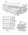
- a glass sheet forming and tempering system is generally indicated by reference numeral 10 and includes topside transfer apparatus 12 that is constructed in accordance with the invention to provide handling of heated glass sheets as a part of a processing operation. Heating of glass sheets is performed in a furnace 14 of the system. Conveyance of the glass sheets during heating is performed on rolls 16 of a horizontal heating conveyor 18.
- the topside transfer apparatus 12 of system 10 is preferably located in a heated ambient such as in the furnace end 20 which is only partially shown. A heated glass sheet is received by the topside transfer apparatus 12 as is hereinafter more fully described and is thereafter deposited by the apparatus on a curved forming mold 22 of the system 10.
- Mold 22 includes an open center ring 24 that is moved horizontally in opposite directions by an actuator 26 as illustrated by arrows 27.
- a quench unit 28 of system 10 includes upper and lower opposed blastheads 30 and 32 having nozzles 34 through which quenching gas is supplied to provide tempering of a formed glass sheet positioned within the quench unit by movement of the ring mold 22 under the operation of the actuator 26.
- the glass sheet topside transfer apparatus 12 includes a downwardly facing surface 36 for receiving and supporting a glass sheet prior to release thereof onto the mold 22 for forming.
- a first set of openings or holes 38 in the surface 36 is provided for drawing a vacuum to support a glass sheet below the surface.
- a second set of openings or holes 40 in the surface 36 supplies pressurized gas at the surface in order to maintain a spaced relationship between the supported glass sheet and the surface.
- the heated glass sheet to be formed can be supported without surface to surface contact such that marring and scratching of the upper glass surface does not take place as the glass sheet is transferred from the conveyor 18 shown in Figure 1 to the bending mold 22.
- the surface 36 has a continuous shape without any abrupt curvature and thereby provides this spaced support by the operation of the vacuum and pressurized gas flows in cooperation with the ambient pressure below the glass sheet.
- a schematically indicated first vacuum blower 42 is located within the heated ambient and communicated with a vacuum chamber 44 defined by a sheet metal housing 46. Operation of blower 42 draws a vacuum within the chamber 44 which is communicated with the vacuum holes in order to draw the vacuum at the downwardly facing surface 36 as previously described. Blower 42 delivers the gas drawn from chamber 44 to the heated ambient within furnace end 20 such that there is no heat loss involved with operation of the apparatus.
- a pressure blower 48 is communicated with a chamber 50 defined by a sheet metal housing 52 within the housing 46. The chamber 50 is communicated with the gas pressure supply holes to supply a downward flow of pressurized gas that maintains a spaced relationship between the supported glass sheet and the surface 36.
- the blower 48 draws heated gas from within the furnace 14 such that there is no chilling of the upper glass surface by the pressurized gas supplied to the downwardly facing surface 36.
- a schematically indicated connection 54 from the first vacuum blower 42 to a control unit 56 and a schematically indicated connection 58 of the control unit to the second pressure blower 48 provide coordinated operation of the blowers to control the relative extents of the vacuum and pressurized gas in order to provide the proper spacing between the surface 36 and the supported glass sheet.
- the downwardly facing surface 36 has a planar shape to receive flat glass sheets for topside support and handling in the manner previously described.
- the apparatus When utilized to handle and transfer hot glass sheets, it is preferable for the apparatus to include a refractory platen 60 that defines the downwardly facing planar surface 36.
- Refractory platen 60 is preferably made from fused silica particles that are sinter bonded so as to have a low coefficient of thermal expansion and hence the ability to maintain planarity upon heating and cooling.
- An upwardly facing surface 62 of platen 60 extends parallel to its downwardly facing surface 36, while side surfaces 64 extend perpendicular to both surfaces 36 and 62 to define the block like construction.
- the platen 60 illustrated in Figures 2 and 4 includes a first set of passages 66 having lower ends that define the set of vacuum holes 38 at the surface 36. Upper ends of passages 66 are communicated with elongated tunnels 68 that extend horizontally between one pair of side surfaces 64 to communicate the vacuum drawn in the chamber 44 illustrated in Figure 1 with the vacuum holes 38.
- a second set of passages 70 in the platen 60 illustrated in Figures 2 through 4 provides for flow of the pressurized gas to the surface 36 from the chamber 50 illustrated in Figure 1.
- Passages 70 are arranged in rows between the tunnels 68 and have upper ends at the upper surface 62 as best seen in Figures 2 and 4.
- Lower ends of the passages 70 have flared shapes that define the second set of holes 40 through which the pressurized gas is supplied to the planar surface 36. Good flow and distribution characteristics are found to result with the flared construction of the lower ends of the pressure passages 70.
- Specific parameters of one platen 60 successfully used includes alternating rows of the vacuum and pressure passages 66 and 70 with the rows spaced 3/4 of an inch apart from each other.
- Each of the rows of vacuum passages 66 includes passages spaced on 1/2 inch centers with a pattern of one passage with 1/8 inch diameter and then two passages with 3/16 inch diameter, such pattern repeating over the entire length of the row.
- Each of the rows of pressure passages 70 includes passages spaced on 1/2 inch centers with -each passage having an 1/8 inch diameter flared to 1/4 inch diameter at the surface 36.
- Successful topside transfer of heated glass sheets 1/8 inch thick was performed by the refractory platen 60 described above by initially drawing a vacuum estimated to be on the equivalent of about 5 inches of water column for the initial pickup during a short time period of about .2 seconds. Thereafter, the vacuum drawn was decreased to be equivalent to about 3-1/2 inches of water column. During both the high pressure vacuum pickup and the subsequent support of the heated glass sheet, the pressurized gas supplied was equivalent to about 3 to 5 inches of water column.
- the topside transfer apparatus 12 is located so that the downwardly facing platen surface 36 is located just above the elevation of a glass sheet being conveyed on the rolls 16 of the heating conveyor 18. After the heating is completed, the glass sheet is conveyed from the phantom line indicated position toward the right to the solid line indicated position as the glass sheet is supported by the vacuum and pressurized gas in the manner previously described. Inertia of the glass sheet moving off of the roller conveyor 18 provides movement thereof into engagement with locators 80 (see also Figure 3) that position the glass sheet. As is hereinafter more fully described, it is also possible for the pressurized gas supplied to the platen surface 36 to be inclined in order to assist the inertia in conveying the glass sheet into engagement with the locators 80.
- a suitable mechanical catcher can be moved into position at the downstream end of the glass sheet to 'prevent it from bouncing off the locators 80 in an upstream direction if this is found to be necessary. It is also possible to utilize a suitable mechanical frame for assisting in conveying the glass sheet into position in engagement with the locators 80 in preparation for the forming operation. Actuator 26 positions the curved mold 22 below the platen surface 36 in preparation for the forming operation.
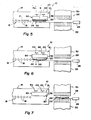
- FIG 8. Another embodiment of the platen 60a is illustrated in Figure 8.
- This platen embodiment 60a has the first and second set of passages 66 and 70 reversed as compared to the previously described embodiment as far as which passages apply the vacuum and which supply the pressurized gas.
- the first set of vacuum passages 66 extend between the lower and upper surfaces of the platen and draw the vacuum at the first set of holes 38 from a vacuum applied at the upper surface of the platen.
- the second set of passages 70 have lower ends that communicate with the second set of holes 4 ' 0 and have upper ends that are communicated with the elongated tunnels 66 through which the pressurized gas is supplied.
- somewhat modified blower and housing structure is necessary to draw the vacuum and supply the pressurized gas.
- the second set of gas supply passages 70 have lower extremities that are inclined in order to provide angled gas flow that provides conveyance of glass sheets along the downwardly facing platen surface 36 in the manner previously discussed. Upper ends of the gas supply passages 70 are inclined in an opposite direction and communicated with the elongated tunnels 68 which extend perpendicular to the direction of glass sheet conveyance along the platen. Such a construction permits the vacuum and pressurized gas holes 38 and 40 to be positioned in an alternating relationship aligned with each other along the direction of conveyance while providing the glass sheet conveyance by the angled gas flow as previously described.
- another embodiment of the platen 60b has the same construction as the platen embodiment 60a illustrated in Figure 8 except that the lower ends of the inclined pressurized gas supply passages 70 have conical shapes for supplying the pressurized gas to the downwardly facing surface 36 of the platen.
- the conical shape of these lower passage ends extends from the junction of the angular passage portions for the full height of the lower ends of the passages.
- another embodiment of the platen 60c has the elongated gas supply tunnels 68 extending parallel to the direction of conveyance as opposed to perpendicular thereto as with the platen embodiments illustrated in Figures -8 and 9.
- the second set of pressurized gas supply passages 70 have inclined configurations along their entire lengths as illustrated in Figure 10 and have conical shapes at their lower ends with the passages essentially straight on the upstream side and with the upper and lower ends being slightly skewed with respect to each other on the downstream side.
- the lower conical passage ends are formed along an axis that is slightly skewed with respect to the central axis of the upper inclined ends of the passages 70.
- Orienting the elongated gas supply tunnels 68 to extend parallel to the direction of conveyance along which the passages 70 are inclined facilitates positioning of the vacuum passages that draw the vacuum at the holes 38 without any spacing problems between these passages and the gas supply tunnels 68.
- FIG. 12 Another platen embodiment 60d is illustrated in Figure 12.
- This platen embodiment 60d has the gas supply passages 70 provided with inclined components both along the direction of conveyance and toward a central axis A of conveyance with the latter inclined component being toward the central axis in opposite directions on opposite sides thereof so as to provide centering of a conveyed glass sheet.
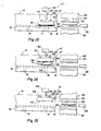
- FIG. 13 Another embodiment of a glass sheet forming and tempering system is identified by 10' and has similar components to the system previously described such that like reference numerals are applied to like components and much of the previous description is applicable and need not be repeated.
- Heating conveyor 18 of the system 10' has the conveyor rolls 16 located below the topside transfer platen 60 which may have any of the constructions previously described.
- An actuator 82 moves the topside transfer platen 60 vertically as indicated by arrows 84.
- the actuator 82 initially moves the platen 60 downwardly into proximity with the heating conveyor 18 as illustrated in Figure 13 to facilitate the initial support of a heated glass sheet which is positioned by the locators 80 in the manner previously described.
- the ring mold 22 is then located at the quench unit 28 by its actuator 26.
- actuator 82 moves the platen 60 upwardly to the position of Figure 14 with the heated glass sheet G supported thereby as shown by phantom line representation and then releases the glass sheet onto the ring mold 22" for forming by the operation of gravity to the mold shape as shown by solid line representation.
- Mold actuator 26 then moves the ring mold 22 from below the platen 60 as illustrated in Figure 14 to the quench unit 28 as illustrated in Figure 15.
- Quenching gas supplied by the upper and lower blastheads 30 and 32 of the quench unit 28 then provides rapid cooling of the formed glass sheet in order to provide tempering of the glass sheet.
- the actuator 82 then moves the platen downwardly to lift the next heated glass sheet as the next cycle commences.
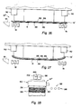
- another glass sheet processing system 10 includes topside transfer or handling apparatus 12' that receives a heated flat glass sheet from a schematically indicated heating conveyor 18 by either of the two modes of operation previously described or by any other suitable mode of transfer.
- System 10 includes a deformable platen 85 that defines the downwardly facing surface 36 at which a vacuum and pressurized gas are supplied to support the glass sheet G in a spaced relationship as previously described.
- a first manifold 86 distributes the vacuum at the surface through a first set of openings or holes and a second manifold 88 distributes the flow of pressurized gas through a second set of openings or holes as previously described.
- One or more actuators as schematically illustrated by 90 move the deformable platen 85 from the planar position of Figure 16 to the curved position of Figure 17 to form the heated glass sheet supported thereby to the curved shape.
- the deformable platen 85 may have different constructions, one of which is a thin steel plate that is deformable and has openings which distribute the vacuum and pressurized gas. This forming is also preferably performed in a heated ambient and may utilize gas jet pumps 91 for supplying heated gas jets that assist in maintaining the glass sheet supports on the deformable platen 85 during the forming operation. After the forming, the formed glass sheet may be annealed or tempered as necessary.
- a loading system 92 is illustrated as including topside transfer apparatus 12" having a movable platen 60.
- the topside transfer apparatus 12" operates to transfer glass sheets from a stack 94 onto an associated conveyor 96 in preparation for processing.
- Suitable locators 80 on the surface 36 of the platen 60 provide accurate positioning of the glass sheet during the loading.
- An actuator 98 moves the platen 60 both vertically as shown by arrows 100 and horizontally as shown by arrows 102.
- Each loading operation of the loading system 92 shown in Figure 18 begins with downward movement of the platen 60 under the operation of actuator 98 such that the surface 36 is positioned in close proximity to the uppermost glass sheet of the stack 94.
- the glass sheet is then received by the application of vacuum and supply of pressurized gas at the surface 36 as previously described. Upward movement of platen 60 is then followed by horizontal movement to above the conveyor 96 whereupon the glass sheet is released by termination of the vacuum.
- This loading system has particular utility in loading glass sheets which have been painted on their upper surfaces with a paint that cures during heating on the conveyor 96 in preparation for further processing such as forming, tempering, or annealing, etc.
Priority Applications (1)
| Application Number | Priority Date | Filing Date | Title |
|---|---|---|---|
| AT85308365T ATE55365T1 (de) | 1984-11-23 | 1985-11-18 | Glasscheibenbehandlungssystem einschliesslich obenliegender transfervorrichtung. |
Applications Claiming Priority (2)
| Application Number | Priority Date | Filing Date | Title |
|---|---|---|---|
| US674083 | 1984-11-23 | ||
| US06/674,083 US4578103A (en) | 1984-11-23 | 1984-11-23 | Glass sheet processing system including topside transfer apparatus |
Publications (2)
| Publication Number | Publication Date |
|---|---|
| EP0182638A1 true EP0182638A1 (fr) | 1986-05-28 |
| EP0182638B1 EP0182638B1 (fr) | 1990-08-08 |
Family
ID=24705239
Family Applications (1)
| Application Number | Title | Priority Date | Filing Date |
|---|---|---|---|
| EP85308365A Expired - Lifetime EP0182638B1 (fr) | 1984-11-23 | 1985-11-18 | Système pour traiter des feuilles de verre y compris appareil de transport surélevé |
Country Status (18)
| Country | Link |
|---|---|
| US (1) | US4578103A (fr) |
| EP (1) | EP0182638B1 (fr) |
| JP (1) | JPS61132528A (fr) |
| KR (1) | KR900005385B1 (fr) |
| AR (1) | AR243141A1 (fr) |
| AT (1) | ATE55365T1 (fr) |
| AU (1) | AU566045B2 (fr) |
| BR (1) | BR8505847A (fr) |
| CA (1) | CA1297678C (fr) |
| DE (1) | DE3579116D1 (fr) |
| EG (1) | EG16977A (fr) |
| ES (1) | ES8700216A1 (fr) |
| FI (1) | FI79517C (fr) |
| IE (1) | IE58804B1 (fr) |
| IN (1) | IN166262B (fr) |
| MX (1) | MX166142B (fr) |
| NZ (1) | NZ214149A (fr) |
| ZA (1) | ZA858679B (fr) |
Cited By (4)
| Publication number | Priority date | Publication date | Assignee | Title |
|---|---|---|---|---|
| FR2591217A1 (fr) * | 1985-12-09 | 1987-06-12 | Ppg Industries Inc | Procede et appareillage de profilage de feuilles, notamment de feuilles de verre |
| EP0228597A2 (fr) * | 1985-12-06 | 1987-07-15 | Ppg Industries, Inc. | Cadre de support à va-et-vient pour démouler à vide |
| DE3721863A1 (de) * | 1987-07-02 | 1989-01-12 | Ver Glaswerke Gmbh | Haltevorrichtung mit saugwirkung fuer glasscheiben und verwendung der haltevorrichtung bei einem verfahren zum biegen von glasscheiben |
| EP0419746A1 (fr) * | 1989-09-28 | 1991-04-03 | Piezo Ceram Electronique | Four annulaire à sole tournante pour conformer à un profil voulu l'une des faces d'ébauches de lentilles optiques par affaissement thermique et application de vide |
Families Citing this family (26)
| Publication number | Priority date | Publication date | Assignee | Title |
|---|---|---|---|---|
| IT1214033B (it) * | 1987-02-03 | 1990-01-05 | Carlomagno Giovanni Maria | Procedimento e dispositivo per esercitare forze su lastre di vetro, in particolare ad elevata temperatura |
| US4767437A (en) * | 1987-03-25 | 1988-08-30 | Ppg Industries, Inc. | Horizontal press bending using a splitting vacuum/pressure pickup |
| JPS6414121A (en) * | 1987-07-07 | 1989-01-18 | Asahi Glass Co Ltd | Bend forming device for plate glass |
| DE68905703T2 (de) * | 1988-08-03 | 1993-07-08 | Nippon Sheet Glass Co Ltd | Vorrichtung zum biegen von glasscheiben. |
| JPH02113817U (fr) * | 1989-02-22 | 1990-09-12 | ||
| US5004491A (en) * | 1990-05-22 | 1991-04-02 | Glasstech, Inc. | Glass sheet forming method and apparatus utilizing lower full surface vacuum mold and upper ring mold |
| US5002599A (en) * | 1990-05-22 | 1991-03-26 | Glasstech, Inc. | Heated glass sheet topside support device |
| US5066321A (en) * | 1990-07-19 | 1991-11-19 | Glasstech, Inc. | Device for positioning hot glass sheets |
| US5156664A (en) * | 1991-03-19 | 1992-10-20 | Glasstech, Inc. | Delivery apparatus for newly formed glass sheet strip |
| DE4203751C2 (de) * | 1992-02-10 | 1993-11-18 | Ver Glaswerke Gmbh | Vorrichtung zum Biegen von Glasscheiben |
| US5286271A (en) * | 1992-07-02 | 1994-02-15 | Ppg Industries, Inc. | Method and apparatus for bending glass sheets |
| US5259859A (en) * | 1992-09-02 | 1993-11-09 | Ppg Industries, Inc. | Lightweight vacuum shuttle |
| CA2141830C (fr) * | 1994-02-14 | 1999-06-01 | Ppg Industries Ohio, Inc. | Methode et installation pour bomber le verre en feuilles |
| CN1130601A (zh) * | 1995-03-06 | 1996-09-11 | 高学明 | 用静压提升法制备钢化玻璃的方法 |
| US5669953A (en) * | 1995-03-07 | 1997-09-23 | Glasstech, Inc. | Glass sheet forming system |
| US5762674A (en) * | 1995-09-27 | 1998-06-09 | Glasstech, Inc. | Apparatus for coating glass sheet ribbon |
| US6038886A (en) * | 1998-08-19 | 2000-03-21 | Glasstech, Inc. | Mold support frame assembly having thermally stable center |
| US6038887A (en) * | 1998-08-19 | 2000-03-21 | Glasstech, Inc. | Apparatus and method for forming glass sheets |
| AU1116100A (en) * | 1998-10-21 | 2000-05-08 | Glasstech Inc. | Uniform distribution quenching of formed glass sheets |
| DE19848373C2 (de) * | 1998-10-21 | 2000-12-07 | Sekurit Saint Gobain Deutsch | Verfahren und Vorrichtung zum Biegen von Glasscheiben mit einer flächigen Biegeform |
| US6428390B1 (en) | 1999-06-29 | 2002-08-06 | Corning Incorporated | Method and apparatus for edge finishing glass sheets |
| US6263705B1 (en) * | 2000-02-08 | 2001-07-24 | Glasstech, Inc. | Hot glass sheet handling apparatus including overlapping roll conveyor and topside transfer platen |
| US6425269B1 (en) * | 2000-06-15 | 2002-07-30 | Glasstech, Inc. | Method for glass sheet forming |
| US7125319B2 (en) | 2003-10-27 | 2006-10-24 | Corning Incorporated | Apparatus and method for grinding and/or polishing an edge of a glass sheet |
| RU2499772C1 (ru) * | 2012-04-23 | 2013-11-27 | Открытое акционерное общество "Саратовский институт стекла" | Способ производства флоат-стекла |
| FR3129937B1 (fr) * | 2021-12-03 | 2023-11-24 | Saint Gobain | Système pour la collecte d’une feuille de verre, procédé de mise en forme d’une feuille de verre au moyen d’un tel système de collecte |
Citations (3)
| Publication number | Priority date | Publication date | Assignee | Title |
|---|---|---|---|---|
| US3223443A (en) * | 1963-10-17 | 1965-12-14 | Pittsburgh Plate Glass Co | Handling of sheet material |
| EP0003391A1 (fr) * | 1978-01-25 | 1979-08-08 | McMaster, Harold A. | Appareil pour le cintrage et la trempe du verre |
| US4202681A (en) * | 1978-01-25 | 1980-05-13 | Mcmaster Harold | Vacuum holder system and method for use in bending glass |
Family Cites Families (2)
| Publication number | Priority date | Publication date | Assignee | Title |
|---|---|---|---|---|
| US3468645A (en) * | 1966-05-09 | 1969-09-23 | Permaglass | Method and apparatus for shaping glass sheets supported on a gas support bed |
| BE790317A (fr) * | 1971-10-19 | 1973-04-19 | Pilkington Brothers Ltd | Appareil et procede pour la separation des portions adjacentes d'une feuille de verre prealablement decoupee |
-
1984
- 1984-11-23 US US06/674,083 patent/US4578103A/en not_active Expired - Lifetime
-
1985
- 1985-11-05 IN IN883/MAS/85A patent/IN166262B/en unknown
- 1985-11-11 NZ NZ214149A patent/NZ214149A/en unknown
- 1985-11-12 ZA ZA858679A patent/ZA858679B/xx unknown
- 1985-11-15 CA CA000495433A patent/CA1297678C/fr not_active Expired - Lifetime
- 1985-11-18 AU AU49986/85A patent/AU566045B2/en not_active Ceased
- 1985-11-18 AT AT85308365T patent/ATE55365T1/de not_active IP Right Cessation
- 1985-11-18 EP EP85308365A patent/EP0182638B1/fr not_active Expired - Lifetime
- 1985-11-18 DE DE8585308365T patent/DE3579116D1/de not_active Expired - Fee Related
- 1985-11-18 IE IE289285A patent/IE58804B1/en not_active IP Right Cessation
- 1985-11-21 AR AR85302342A patent/AR243141A1/es active
- 1985-11-21 EG EG742/85A patent/EG16977A/xx active
- 1985-11-21 FI FI854611A patent/FI79517C/fi not_active IP Right Cessation
- 1985-11-21 BR BR8505847A patent/BR8505847A/pt not_active IP Right Cessation
- 1985-11-22 JP JP60263620A patent/JPS61132528A/ja active Granted
- 1985-11-22 MX MX000683A patent/MX166142B/es unknown
- 1985-11-22 KR KR1019850008745A patent/KR900005385B1/ko not_active IP Right Cessation
- 1985-11-22 ES ES549184A patent/ES8700216A1/es not_active Expired
Patent Citations (3)
| Publication number | Priority date | Publication date | Assignee | Title |
|---|---|---|---|---|
| US3223443A (en) * | 1963-10-17 | 1965-12-14 | Pittsburgh Plate Glass Co | Handling of sheet material |
| EP0003391A1 (fr) * | 1978-01-25 | 1979-08-08 | McMaster, Harold A. | Appareil pour le cintrage et la trempe du verre |
| US4202681A (en) * | 1978-01-25 | 1980-05-13 | Mcmaster Harold | Vacuum holder system and method for use in bending glass |
Cited By (5)
| Publication number | Priority date | Publication date | Assignee | Title |
|---|---|---|---|---|
| EP0228597A2 (fr) * | 1985-12-06 | 1987-07-15 | Ppg Industries, Inc. | Cadre de support à va-et-vient pour démouler à vide |
| EP0228597A3 (en) * | 1985-12-06 | 1988-09-21 | Ppg Industries, Inc. | Shuttling support frame for vacuum pickup |
| FR2591217A1 (fr) * | 1985-12-09 | 1987-06-12 | Ppg Industries Inc | Procede et appareillage de profilage de feuilles, notamment de feuilles de verre |
| DE3721863A1 (de) * | 1987-07-02 | 1989-01-12 | Ver Glaswerke Gmbh | Haltevorrichtung mit saugwirkung fuer glasscheiben und verwendung der haltevorrichtung bei einem verfahren zum biegen von glasscheiben |
| EP0419746A1 (fr) * | 1989-09-28 | 1991-04-03 | Piezo Ceram Electronique | Four annulaire à sole tournante pour conformer à un profil voulu l'une des faces d'ébauches de lentilles optiques par affaissement thermique et application de vide |
Also Published As
| Publication number | Publication date |
|---|---|
| BR8505847A (pt) | 1986-08-12 |
| JPS61132528A (ja) | 1986-06-20 |
| ES8700216A1 (es) | 1986-10-01 |
| FI79517C (fi) | 1990-01-10 |
| NZ214149A (en) | 1987-04-30 |
| DE3579116D1 (de) | 1990-09-13 |
| IE852892L (en) | 1986-05-23 |
| ZA858679B (en) | 1986-07-30 |
| JPS6359973B2 (fr) | 1988-11-22 |
| EP0182638B1 (fr) | 1990-08-08 |
| MX166142B (es) | 1992-12-22 |
| AU4998685A (en) | 1986-05-29 |
| KR860003986A (ko) | 1986-06-16 |
| ATE55365T1 (de) | 1990-08-15 |
| CA1297678C (fr) | 1992-03-24 |
| IE58804B1 (en) | 1993-11-17 |
| AU566045B2 (en) | 1987-10-08 |
| KR900005385B1 (ko) | 1990-07-28 |
| EG16977A (en) | 1992-06-30 |
| FI854611A0 (fi) | 1985-11-21 |
| AR243141A1 (es) | 1993-07-30 |
| IN166262B (fr) | 1990-04-07 |
| ES549184A0 (es) | 1986-10-01 |
| FI854611A (fi) | 1986-05-24 |
| FI79517B (fi) | 1989-09-29 |
| US4578103A (en) | 1986-03-25 |
Similar Documents
| Publication | Publication Date | Title |
|---|---|---|
| US4578103A (en) | Glass sheet processing system including topside transfer apparatus | |
| US4615724A (en) | Glass sheet forming system including topside transfer apparatus | |
| US8132428B2 (en) | Glass sheet forming method | |
| US4767437A (en) | Horizontal press bending using a splitting vacuum/pressure pickup | |
| EP0005306B1 (fr) | Appareil et procédé pour cintrer du verre | |
| US4277276A (en) | Method and apparatus for shaping glass sheets using deformable vacuum mold | |
| JPH06127961A (ja) | シート材を成形する装置と方法 | |
| JPH07267663A (ja) | 熱軟化板材料成形装置および方法 | |
| JP2009512617A5 (fr) | ||
| US6574990B2 (en) | Process for bend-shaping a glass plate | |
| ITMI972771A1 (it) | Procedimento ed apparecchiatura per piegare materiale in lastra termo-rammollibile in particolare lastre di vetro | |
| JPS6141854B2 (fr) | ||
| US5992180A (en) | Method and apparatus for bend-shaping a glass plate | |
| US4357156A (en) | Minimizing surface distortion while shaping glass sheets | |
| KR100685710B1 (ko) | 오버래핑 롤 컨베이어 및 상부 이송 플래튼을 포함하는고온 글라스 시트 핸들링 장치 | |
| US4199341A (en) | Glass lift mechanism for and method of press bending glass sheets | |
| JPS62260726A (ja) | 板状体の移送方法及び装置、並びにその移送中にそれを曲げる方法 |
Legal Events
| Date | Code | Title | Description |
|---|---|---|---|
| PUAI | Public reference made under article 153(3) epc to a published international application that has entered the european phase |
Free format text: ORIGINAL CODE: 0009012 |
|
| AK | Designated contracting states |
Kind code of ref document: A1 Designated state(s): AT BE CH DE FR GB IT LI LU NL SE |
|
| 17P | Request for examination filed |
Effective date: 19861117 |
|
| 17Q | First examination report despatched |
Effective date: 19870625 |
|
| GRAA | (expected) grant |
Free format text: ORIGINAL CODE: 0009210 |
|
| AK | Designated contracting states |
Kind code of ref document: B1 Designated state(s): AT BE CH DE FR GB IT LI LU NL SE |
|
| PG25 | Lapsed in a contracting state [announced via postgrant information from national office to epo] |
Ref country code: SE Free format text: LAPSE BECAUSE OF FAILURE TO SUBMIT A TRANSLATION OF THE DESCRIPTION OR TO PAY THE FEE WITHIN THE PRESCRIBED TIME-LIMIT Effective date: 19900808 Ref country code: NL Effective date: 19900808 Ref country code: LI Effective date: 19900808 Ref country code: CH Effective date: 19900808 Ref country code: AT Effective date: 19900808 |
|
| REF | Corresponds to: |
Ref document number: 55365 Country of ref document: AT Date of ref document: 19900815 Kind code of ref document: T |
|
| REF | Corresponds to: |
Ref document number: 3579116 Country of ref document: DE Date of ref document: 19900913 |
|
| ET | Fr: translation filed | ||
| ITF | It: translation for a ep patent filed |
Owner name: STUDIO TORTA SOCIETA' SEMPLICE |
|
| PGFP | Annual fee paid to national office [announced via postgrant information from national office to epo] |
Ref country code: SE Payment date: 19901114 Year of fee payment: 6 |
|
| REG | Reference to a national code |
Ref country code: CH Ref legal event code: PL |
|
| NLV1 | Nl: lapsed or annulled due to failure to fulfill the requirements of art. 29p and 29m of the patents act | ||
| PLBE | No opposition filed within time limit |
Free format text: ORIGINAL CODE: 0009261 |
|
| STAA | Information on the status of an ep patent application or granted ep patent |
Free format text: STATUS: NO OPPOSITION FILED WITHIN TIME LIMIT |
|
| 26N | No opposition filed | ||
| ITTA | It: last paid annual fee | ||
| PGFP | Annual fee paid to national office [announced via postgrant information from national office to epo] |
Ref country code: LU Payment date: 19931001 Year of fee payment: 9 |
|
| EPTA | Lu: last paid annual fee | ||
| PG25 | Lapsed in a contracting state [announced via postgrant information from national office to epo] |
Ref country code: LU Free format text: LAPSE BECAUSE OF NON-PAYMENT OF DUE FEES Effective date: 19941118 |
|
| REG | Reference to a national code |
Ref country code: GB Ref legal event code: IF02 |
|
| PGFP | Annual fee paid to national office [announced via postgrant information from national office to epo] |
Ref country code: GB Payment date: 20031002 Year of fee payment: 19 |
|
| PGFP | Annual fee paid to national office [announced via postgrant information from national office to epo] |
Ref country code: DE Payment date: 20031128 Year of fee payment: 19 |
|
| PGFP | Annual fee paid to national office [announced via postgrant information from national office to epo] |
Ref country code: BE Payment date: 20031216 Year of fee payment: 19 |
|
| PGFP | Annual fee paid to national office [announced via postgrant information from national office to epo] |
Ref country code: FR Payment date: 20041105 Year of fee payment: 20 |
|
| PG25 | Lapsed in a contracting state [announced via postgrant information from national office to epo] |
Ref country code: GB Free format text: LAPSE BECAUSE OF NON-PAYMENT OF DUE FEES Effective date: 20041118 |
|
| PG25 | Lapsed in a contracting state [announced via postgrant information from national office to epo] |
Ref country code: BE Free format text: LAPSE BECAUSE OF NON-PAYMENT OF DUE FEES Effective date: 20041130 |
|
| BERE | Be: lapsed |
Owner name: *GLASSTECH INC. Effective date: 20041130 |
|
| PG25 | Lapsed in a contracting state [announced via postgrant information from national office to epo] |
Ref country code: DE Free format text: LAPSE BECAUSE OF NON-PAYMENT OF DUE FEES Effective date: 20050601 |
|
| GBPC | Gb: european patent ceased through non-payment of renewal fee |
Effective date: 20041118 |
|
| BERE | Be: lapsed |
Owner name: *GLASSTECH INC. Effective date: 20041130 |