EP0182606B1 - Independent rear wheel suspension - Google Patents
Independent rear wheel suspension Download PDFInfo
- Publication number
- EP0182606B1 EP0182606B1 EP85308275A EP85308275A EP0182606B1 EP 0182606 B1 EP0182606 B1 EP 0182606B1 EP 85308275 A EP85308275 A EP 85308275A EP 85308275 A EP85308275 A EP 85308275A EP 0182606 B1 EP0182606 B1 EP 0182606B1
- Authority
- EP
- European Patent Office
- Prior art keywords
- suspension
- control arm
- wheel carrier
- chassis
- pivotally attached
- Prior art date
- Legal status (The legal status is an assumption and is not a legal conclusion. Google has not performed a legal analysis and makes no representation as to the accuracy of the status listed.)
- Expired - Lifetime
Links
- 239000000725 suspension Substances 0.000 title claims description 29
- 239000006096 absorbing agent Substances 0.000 claims description 3
- 230000035939 shock Effects 0.000 claims description 3
- 238000010276 construction Methods 0.000 description 4
- 230000000712 assembly Effects 0.000 description 2
- 238000000429 assembly Methods 0.000 description 2
- 244000043261 Hevea brasiliensis Species 0.000 description 1
- 230000009286 beneficial effect Effects 0.000 description 1
- 150000001875 compounds Chemical class 0.000 description 1
- 229920001971 elastomer Polymers 0.000 description 1
- 230000002349 favourable effect Effects 0.000 description 1
- 229920003052 natural elastomer Polymers 0.000 description 1
- 229920001194 natural rubber Polymers 0.000 description 1
- 239000003381 stabilizer Substances 0.000 description 1
Images

Classifications
-
- B—PERFORMING OPERATIONS; TRANSPORTING
- B60—VEHICLES IN GENERAL
- B60G—VEHICLE SUSPENSION ARRANGEMENTS
- B60G3/00—Resilient suspensions for a single wheel
- B60G3/18—Resilient suspensions for a single wheel with two or more pivoted arms, e.g. parallelogram
- B60G3/20—Resilient suspensions for a single wheel with two or more pivoted arms, e.g. parallelogram all arms being rigid
- B60G3/202—Resilient suspensions for a single wheel with two or more pivoted arms, e.g. parallelogram all arms being rigid having one longitudinal arm and two parallel transversal arms, e.g. dual-link type strut suspension
-
- B—PERFORMING OPERATIONS; TRANSPORTING
- B60—VEHICLES IN GENERAL
- B60G—VEHICLE SUSPENSION ARRANGEMENTS
- B60G15/00—Resilient suspensions characterised by arrangement, location or type of combined spring and vibration damper, e.g. telescopic type
- B60G15/02—Resilient suspensions characterised by arrangement, location or type of combined spring and vibration damper, e.g. telescopic type having mechanical spring
- B60G15/06—Resilient suspensions characterised by arrangement, location or type of combined spring and vibration damper, e.g. telescopic type having mechanical spring and fluid damper
-
- B—PERFORMING OPERATIONS; TRANSPORTING
- B60—VEHICLES IN GENERAL
- B60G—VEHICLE SUSPENSION ARRANGEMENTS
- B60G15/00—Resilient suspensions characterised by arrangement, location or type of combined spring and vibration damper, e.g. telescopic type
- B60G15/08—Resilient suspensions characterised by arrangement, location or type of combined spring and vibration damper, e.g. telescopic type having fluid spring
- B60G15/10—Resilient suspensions characterised by arrangement, location or type of combined spring and vibration damper, e.g. telescopic type having fluid spring and mechanical damper or dynamic damper
-
- B—PERFORMING OPERATIONS; TRANSPORTING
- B60—VEHICLES IN GENERAL
- B60G—VEHICLE SUSPENSION ARRANGEMENTS
- B60G7/00—Pivoted suspension arms; Accessories thereof
-
- B—PERFORMING OPERATIONS; TRANSPORTING
- B60—VEHICLES IN GENERAL
- B60G—VEHICLE SUSPENSION ARRANGEMENTS
- B60G2200/00—Indexing codes relating to suspension types
- B60G2200/10—Independent suspensions
- B60G2200/18—Multilink suspensions, e.g. elastokinematic arrangements
- B60G2200/182—Multilink suspensions, e.g. elastokinematic arrangements with one longitudinal arm or rod and lateral rods
-
- B—PERFORMING OPERATIONS; TRANSPORTING
- B60—VEHICLES IN GENERAL
- B60G—VEHICLE SUSPENSION ARRANGEMENTS
- B60G2202/00—Indexing codes relating to the type of spring, damper or actuator
- B60G2202/10—Type of spring
- B60G2202/12—Wound spring
-
- B—PERFORMING OPERATIONS; TRANSPORTING
- B60—VEHICLES IN GENERAL
- B60G—VEHICLE SUSPENSION ARRANGEMENTS
- B60G2202/00—Indexing codes relating to the type of spring, damper or actuator
- B60G2202/20—Type of damper
- B60G2202/24—Fluid damper
-
- B—PERFORMING OPERATIONS; TRANSPORTING
- B60—VEHICLES IN GENERAL
- B60G—VEHICLE SUSPENSION ARRANGEMENTS
- B60G2204/00—Indexing codes related to suspensions per se or to auxiliary parts
- B60G2204/10—Mounting of suspension elements
- B60G2204/12—Mounting of springs or dampers
- B60G2204/124—Mounting of coil springs
- B60G2204/1244—Mounting of coil springs on a suspension arm
Definitions
- This invention relates generally to independent wheel suspension sytems for motor vehicles and more particularly to a short-long arm type independent rear suspension for motor vehicles.
- U.S. Patent 3,189,118 to Arning discloses a system in which roll understeer results from convergence of the axes included between a lower control arm and the frame and wheel carrier.
- U.S. Patent 3,327,803 to Cote et al discloses a suspension employing two pairs of transverse tie rods combined with longitudinal lower arms.
- U.S. Patents 4,245,853 and 4,269,432 to Inoue et al disclose suspension systems for controlling toe in during cornering by the use of converging independent lower control arms in combination with a longitudinal tension strut.
- U.S. Patent 4,457,537 to von der Ohe et al discloses a suspension with a transverse, laterally offset track rod and upper and lower transverse wishbone arms articulated at a single point to the wheel carrier.
- EP-A-083,183 discloses an independent rear wheel suspension for a motor vehicle having front wheel drive including a wheel support member and two laterally extending control arms pivotally connected at their outboard ends to the wheel support member and at their inboard ends to the vehicle chassis.
- the two laterally extending control arms are longitudinally and vertically spaced apart.
- a trailing arm is rigidly connected to the wheel support member and has its front end connected to the chassis through a resilient bushing. As the wheel recesses, the bushing allows the front end of the trailing arm to move inboard and promotes the wheel to toe-in during recession.
- the present invention seeks to provide a suspension system in which roll understeer is achieved but which has favourable space requirements.
- the suspension of the present invention provides for increased cargo space because unlike systems employing MacPherson struts, a large tower is not needed to house shock absorber and spring components.
- the invention is further advantageous in that beneficial toe-in of the outside wheel is achieved during turning maneuvers and camber and track width changes during jounce and rebound are minimized.
- Control of toe-in during cornering results from placing the connection of the upper control arm to the wheel carrier forward of the spindle such that the axis of elasticities responsive to cornering force contacts the road surface at a point trailing the location at which the cornering force normally acts upon the wheel.
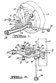
- the wheel suspension 16 shown in Figures 1-3 comprises a ⁇ wheel carrier 20 having a spindle 4 upon which a wheel and tire assembly 2 is mounted, a transverse upper control arm 24 and a transverse lower control arm 36.
- Upper control arm 24 is oriented transversely to the vehicle centerline and is pivotally mounted to the chassis at its inboard ends 25 and 26.
- ends 25 and 26 of upper control arm 24 are attached to the chassis 28 by means of bolts extending through resilient bushing assmblies 30 and 31 mounted in ends 25 and 26 respectively.
- Each inboard mounting position of upper control arm 24 is preferably equidistant from the vehicle's longitudinal centerline.
- each bushing assembly has a flanged outer sleeve 52 which is coaxial with and surrounds a cylindrical elastomeric bushing 54.
- Inner sleeve 56 is mounted concentrically within cylindrical elastomeric bushing 54 which may be of natural rubber or other rubber compounds.
- bolt 58 is slidably engaged with inner sleeve 56 to permit mounting and dismounting of each bushing assembly.
- bushing assembly 22 comprises an elastomeric element having a cylindrical section 60 within a cylindrical bore formed within boss 21, a frustroconical section 62 extending from said bore and an annular section 63 clamped between washer 64 and boss 21.
- Frustroconical section 62 and annular section 63 of bushing assembly 22 cause bushing assembly 22 to have an asymmetric response to forces tending to rotate wheel carrier 20 in a vertical plane.
- spindle 4 will be subjected to a force acting in the rearward direction. This force will cause wheel carrier 20 to rotate rearward to the extent permitted by frustroconical section 62, which will be compressed between boss 21 and outer end 27 of the upper control arm.
- annular section 63 will control rotation of wheel carrier 20 in a forward direction. As wheel carrier 20 rotates forward in response to braking torque, annular section 63 will be compressed between boss 21 and washer 64.
- the asymmetric response characteristic of bushing assembly 22 thus results from the fact that frustroconical section 62 is relatively more yielding to force acting in an axial direction than is annular section 63.
- lower control arm 36 has a bifurcated outboard end pivotally attached to wheel carrier 20 at first and second locations, which are longitudinally forward and rearward of spindle 4, by means of bushing assemblies 32 and 33.
- Bolts 70 and 71 which are threadably engaged with wheel carrier 20, clamp bushing assemblies 32 and 33 to wheel carrier 20.
- lower control arm 36 is pivotally attached to chassis 28 by means of bushing assembly 34.
- Spring 40 and shock absorber 42 are conventionally mounted between lower control arm 36 and chassis 28.
- longitudinal strut 44 is pivotally mounted to chassis 28 by bushing assembly 46 at its leading end and pivotally mounted at its trailing end to lower control arm 36 by bushing assembly 48.
- a transverse stabilizer bar (not shown) may be provided with such bar pivotally mounted to the chassis and resiliently mounted to the lower control arms.
- a multi- piece upper control arm assembly 72 comprises a first or trailing arm element 74, a second, or leading arm element 76, and central bushing assembly 78. Both arm elements are rigidly attached to the central bushing assembly at their outboard ends 80 and 82.
- Central bushing assembly 78 is similar in construction to bushing assembly 22 inasmuch as both contain a frustroconical section which resiliently allows limited rearward rotation of wheel carrier 20 in a vertical plane during wheel recession and annular section 63 which resiliently resists forward rotation of wheel carrier 20 in a vertical plane during brake operation.
- Outer ends 80 and 82 of the first and second arm elements are rigidly clamped to bushing assembly 78 by bolt 65 and nut 66.
- Figure 5 shows the cross-sectional construction of bushing assembly 78.
Description
- This invention relates generally to independent wheel suspension sytems for motor vehicles and more particularly to a short-long arm type independent rear suspension for motor vehicles.
- The desirability of roll understeer has long been recognized and various suspension designs have been produced with the roll understeer characteristic in mind.
- U.S. Patent 3,189,118 to Arning discloses a system in which roll understeer results from convergence of the axes included between a lower control arm and the frame and wheel carrier.
- U.S. Patent 3,327,803 to Cote et al discloses a suspension employing two pairs of transverse tie rods combined with longitudinal lower arms. U.S. Patents 4,245,853 and 4,269,432 to Inoue et al disclose suspension systems for controlling toe in during cornering by the use of converging independent lower control arms in combination with a longitudinal tension strut.
- U.S. Patent 4,444,415 to von der Ohe discloses a suspension system in which each rear wheel carrier is guided by give separate articulated links.
- Finally, U.S. Patent 4,457,537 to von der Ohe et al discloses a suspension with a transverse, laterally offset track rod and upper and lower transverse wishbone arms articulated at a single point to the wheel carrier.
- Each of these systems produces roll understeer by causing the wheel at the outside of a turn to toe in.
- EP-A-083,183 discloses an independent rear wheel suspension for a motor vehicle having front wheel drive including a wheel support member and two laterally extending control arms pivotally connected at their outboard ends to the wheel support member and at their inboard ends to the vehicle chassis. The two laterally extending control arms are longitudinally and vertically spaced apart. A trailing arm is rigidly connected to the wheel support member and has its front end connected to the chassis through a resilient bushing. As the wheel recesses, the bushing allows the front end of the trailing arm to move inboard and promotes the wheel to toe-in during recession.
- The present invention seeks to provide a suspension system in which roll understeer is achieved but which has favourable space requirements.
- According to the present invention, there is provided an independent suspension for a vehicle as herein set forth in
Claim 1. - The suspension of the present invention provides for increased cargo space because unlike systems employing MacPherson struts, a large tower is not needed to house shock absorber and spring components. The invention is further advantageous in that beneficial toe-in of the outside wheel is achieved during turning maneuvers and camber and track width changes during jounce and rebound are minimized. Control of toe-in during cornering results from placing the connection of the upper control arm to the wheel carrier forward of the spindle such that the axis of elasticities responsive to cornering force contacts the road surface at a point trailing the location at which the cornering force normally acts upon the wheel.
- The invention will now be described further, by way of example, with reference to the accompanying drawings, in which:
- Figure 1 is a perspective view of a left rear independent suspension according to this invention;
- Figure 2 is a plan view of the left rear suspension shown in Figure 1;
- Figure 3 is a side elevation of the suspension shown in Figures 1 and 2;
- Figure 4 is a plan view of an alternative embodiment of the suspension shown in Figures 1-3; and
- Figure 5 is a cross sectional view of the several suspension bushings shown in Figures 1-4.
- Generally, the
wheel suspension 16 shown in Figures 1-3 comprises a·wheel carrier 20 having aspindle 4 upon which a wheel andtire assembly 2 is mounted, a transverseupper control arm 24 and a transverselower control arm 36.Upper control arm 24 is oriented transversely to the vehicle centerline and is pivotally mounted to the chassis at itsinboard ends - As shown in Figure 2,
ends upper control arm 24 are attached to thechassis 28 by means of bolts extending through resilient bushing assmblies 30 and 31 mounted inends upper control arm 24 is preferably equidistant from the vehicle's longitudinal centerline. - The general construction of bushings 30 and 31 as well as the construction of lower
control arm bushings longitudinal strut bushings outer sleeve 52 which is coaxial with and surrounds a cylindricalelastomeric bushing 54.Inner sleeve 56 is mounted concentrically within cylindricalelastomeric bushing 54 which may be of natural rubber or other rubber compounds. Finally,bolt 58 is slidably engaged withinner sleeve 56 to permit mounting and dismounting of each bushing assembly. -
Upper control arm 24 is pivotally attached at itsoutboard end 27 toboss 21, which is integral withwheel carrier 20, by means ofbushing assembly 22 which is mounted withinboss 21. As shown in Figure 3,bushing assembly 22 comprises an elastomeric element having acylindrical section 60 within a cylindrical bore formed withinboss 21, afrustroconical section 62 extending from said bore and anannular section 63 clamped between washer 64 andboss 21. -
Bushing assembly 22,boss 21 andend 27 ofcontrol arm 24 are clamped together bybolt 65 andnut 66. -
Frustroconical section 62 andannular section 63 ofbushing assembly 22 causebushing assembly 22 to have an asymmetric response to forces tending to rotatewheel carrier 20 in a vertical plane. Thus, when roadwheel andtire assembly 2 strike an obstruction in the roadway,spindle 4 will be subjected to a force acting in the rearward direction. This force will causewheel carrier 20 to rotate rearward to the extent permitted byfrustroconical section 62, which will be compressed betweenboss 21 andouter end 27 of the upper control arm. - During braking,
annular section 63 will control rotation ofwheel carrier 20 in a forward direction. Aswheel carrier 20 rotates forward in response to braking torque,annular section 63 will be compressed betweenboss 21 and washer 64. The asymmetric response characteristic ofbushing assembly 22 thus results from the fact thatfrustroconical section 62 is relatively more yielding to force acting in an axial direction than isannular section 63. - As shown with particularity in Figure 3,
lower control arm 36 has a bifurcated outboard end pivotally attached towheel carrier 20 at first and second locations, which are longitudinally forward and rearward ofspindle 4, by means ofbushing assemblies Bolts 70 and 71, which are threadably engaged withwheel carrier 20,clamp bushing assemblies wheel carrier 20. As shown in Figures 1 and 2,lower control arm 36 is pivotally attached tochassis 28 by means ofbushing assembly 34. -
Spring 40 andshock absorber 42 are conventionally mounted betweenlower control arm 36 andchassis 28. Finally,longitudinal strut 44 is pivotally mounted tochassis 28 bybushing assembly 46 at its leading end and pivotally mounted at its trailing end tolower control arm 36 bybushing assembly 48. In accord with conventional practice a transverse stabilizer bar (not shown) may be provided with such bar pivotally mounted to the chassis and resiliently mounted to the lower control arms. - An alternate preferred embodiment of the present invention is shown in Figure 4. A multi- piece upper
control arm assembly 72 comprises a first or trailing arm element 74, a second, or leadingarm element 76, andcentral bushing assembly 78. Both arm elements are rigidly attached to the central bushing assembly at theiroutboard ends Central bushing assembly 78 is similar in construction to bushingassembly 22 inasmuch as both contain a frustroconical section which resiliently allows limited rearward rotation ofwheel carrier 20 in a vertical plane during wheel recession andannular section 63 which resiliently resists forward rotation ofwheel carrier 20 in a vertical plane during brake operation.Outer ends assembly 78 bybolt 65 andnut 66. Figure 5 shows the cross-sectional construction ofbushing assembly 78. - The previously described toe angle control during cornering maneuvers will now be described in detail. As shown in Figure 3, if one constructs the axis of elasticities linking the center of
bushing assembly 22 and the midpoint of a straight line connecting the lower controlarm attaching bushings upper control arm 24 is attached towheel carrier 20 atboss 21, which is longitudinally forward ofspindle 4. As shown in Figures 2 and 3, cornering force Fc acts normally upon said wheel and tire assembly.
Claims (11)
Applications Claiming Priority (2)
| Application Number | Priority Date | Filing Date | Title |
|---|---|---|---|
| US06/671,644 US4848788A (en) | 1984-11-15 | 1984-11-15 | Independent rear wheel suspension with offset connection between upper control arm and wheel carrier |
| US671644 | 1984-11-15 |
Publications (3)
| Publication Number | Publication Date |
|---|---|
| EP0182606A2 EP0182606A2 (en) | 1986-05-28 |
| EP0182606A3 EP0182606A3 (en) | 1988-10-19 |
| EP0182606B1 true EP0182606B1 (en) | 1990-07-04 |
Family
ID=24695336
Family Applications (1)
| Application Number | Title | Priority Date | Filing Date |
|---|---|---|---|
| EP85308275A Expired - Lifetime EP0182606B1 (en) | 1984-11-15 | 1985-11-13 | Independent rear wheel suspension |
Country Status (6)
| Country | Link |
|---|---|
| US (1) | US4848788A (en) |
| EP (1) | EP0182606B1 (en) |
| JP (1) | JPS61119415A (en) |
| CA (1) | CA1244493A (en) |
| DE (1) | DE3578555D1 (en) |
| ES (1) | ES8701618A1 (en) |
Families Citing this family (19)
| Publication number | Priority date | Publication date | Assignee | Title |
|---|---|---|---|---|
| JP2811303B2 (en) * | 1986-10-27 | 1998-10-15 | 富士重工業株式会社 | Rear wheel suspension for automobile |
| JP2518349B2 (en) * | 1988-04-19 | 1996-07-24 | トヨタ自動車株式会社 | Rear suspension for vehicles |
| FR2695595B1 (en) * | 1992-09-15 | 1994-11-25 | Renault | Rear axle with independent wheels for motor vehicle. |
| US5820150A (en) * | 1993-04-14 | 1998-10-13 | Oshkosh Truck Corporation | Independent suspensions for lowering height of vehicle frame |
| FR2726227B1 (en) * | 1994-10-26 | 1997-01-03 | Renault | SUSPENSION FOR AN INDEPENDENT REAR WHEEL TRAIN OF A MOTOR VEHICLE |
| US5556119A (en) * | 1995-02-17 | 1996-09-17 | Trw Inc. | Control arm for use in a vehicle wheel suspension system |
| ATE461060T1 (en) * | 2001-05-03 | 2010-04-15 | Technology Investments Ltd | MODULAR BALL JOINT ARRANGEMENT |
| GB2468302B (en) * | 2009-03-03 | 2013-04-03 | Gordon Murray Design Ltd | Vehicle suspension |
| US20120121329A1 (en) * | 2010-11-12 | 2012-05-17 | Mike Gunther | Alkali silica reactivity (ASR) resistant aggregate concrete |
| US9469173B2 (en) * | 2011-11-14 | 2016-10-18 | Gordon Murray Design Limited | Vehicle suspension |
| DE102012200001A1 (en) * | 2012-01-02 | 2013-07-04 | Ford Global Technologies, Llc | Rubber-metal bearing for trapezoidal-link in wheel suspension, has rubber elastic body fastened and arranged between outer bush and inner bush, where outer bush has front end surface at which leading elastic damping element is mounted |
| DE102013205335A1 (en) * | 2013-03-26 | 2014-10-02 | Ford Global Technologies, Llc | Independent suspension for the non-driven wheels of a vehicle |
| GB2525901A (en) * | 2014-05-08 | 2015-11-11 | Gordon Murray Design Ltd | Vehicle suspension |
| RU2693613C1 (en) * | 2015-07-30 | 2019-07-03 | Бомбардье Рекриэйшенел Продактс Инк. | Trunnion for vehicle suspension assembly |
| DE102016220786B4 (en) * | 2016-10-24 | 2024-03-28 | Ford Global Technologies, Llc | Rear suspension for motor vehicles |
| CZ2017327A3 (en) * | 2017-06-07 | 2018-12-19 | České vysoké učenà technické v Praze | A device for car and/or aircraft wheel suspension |
| DE102018205429B4 (en) | 2018-04-11 | 2019-10-24 | Ford Global Technologies, Llc | Rear wheel suspension system of a motor vehicle, in particular of an electrically driven motor vehicle |
| CN114537067A (en) * | 2020-11-26 | 2022-05-27 | 比亚迪股份有限公司 | Rear suspension assembly, rear suspension structure and vehicle |
| DE102021100178A1 (en) * | 2021-01-08 | 2022-07-14 | Dr. Ing. H.C. F. Porsche Aktiengesellschaft | Multi-link motor vehicle axle |
Citations (1)
| Publication number | Priority date | Publication date | Assignee | Title |
|---|---|---|---|---|
| FR2496564A1 (en) * | 1980-12-23 | 1982-06-25 | Daimler Benz Ag | INDEPENDENT WHEEL SUSPENSION FOR MOTOR VEHICLES |
Family Cites Families (12)
| Publication number | Priority date | Publication date | Assignee | Title |
|---|---|---|---|---|
| DE819633C (en) * | 1949-05-16 | 1951-11-05 | Daimler Benz Ag | Suspension of motor vehicles independently by means of two connecting rods, in particular the steering wheels |
| FR1209266A (en) * | 1958-07-16 | 1960-03-01 | Independent wheel suspension for motor vehicle | |
| US3189118A (en) * | 1960-12-22 | 1965-06-15 | Ford Motor Co | Vehicle rear wheel suspension |
| US3327803A (en) * | 1964-12-22 | 1967-06-27 | Gen Motors Corp | Independent rear wheel suspension |
| US3888472A (en) * | 1974-04-25 | 1975-06-10 | Gen Tire & Rubber Co | Suspension insert for a two-headed resilient bushing |
| JPS59966Y2 (en) * | 1978-09-14 | 1984-01-12 | マツダ株式会社 | Automotive rear wheel suspension system |
| US4269432A (en) * | 1978-05-24 | 1981-05-26 | Toyo Kogyo Co., Ltd. | Independent wheel suspension for motor vehicles |
| DE2840368A1 (en) * | 1978-09-16 | 1980-03-27 | Daimler Benz Ag | INDEPENDENT WHEEL SUSPENSION |
| DE3046729C2 (en) * | 1980-12-11 | 1985-05-15 | Europäisches Laboratorium für Molekularbiologie (EMBL), 6900 Heidelberg | Thermostatic plate for an electrophoresis device |
| DE3048837A1 (en) * | 1980-12-23 | 1982-07-01 | Daimler-Benz Ag, 7000 Stuttgart | INDEPENDENT WHEEL SUSPENSION |
| DE3048794C1 (en) * | 1980-12-23 | 1982-08-12 | Daimler-Benz Ag, 7000 Stuttgart | Independent wheel suspension for motor vehicles |
| US4456282A (en) * | 1981-12-24 | 1984-06-26 | Ford Motor Company | Independent rear wheel suspension with a toe angle controlling trailing arm |
-
1984
- 1984-11-15 US US06/671,644 patent/US4848788A/en not_active Expired - Lifetime
-
1985
- 1985-10-24 CA CA000493721A patent/CA1244493A/en not_active Expired
- 1985-11-13 DE DE8585308275T patent/DE3578555D1/en not_active Expired - Lifetime
- 1985-11-13 EP EP85308275A patent/EP0182606B1/en not_active Expired - Lifetime
- 1985-11-14 ES ES548875A patent/ES8701618A1/en not_active Expired
- 1985-11-14 JP JP60253919A patent/JPS61119415A/en active Pending
Patent Citations (1)
| Publication number | Priority date | Publication date | Assignee | Title |
|---|---|---|---|---|
| FR2496564A1 (en) * | 1980-12-23 | 1982-06-25 | Daimler Benz Ag | INDEPENDENT WHEEL SUSPENSION FOR MOTOR VEHICLES |
Also Published As
| Publication number | Publication date |
|---|---|
| EP0182606A2 (en) | 1986-05-28 |
| ES548875A0 (en) | 1986-12-01 |
| JPS61119415A (en) | 1986-06-06 |
| ES8701618A1 (en) | 1986-12-01 |
| DE3578555D1 (en) | 1990-08-09 |
| CA1244493A (en) | 1988-11-08 |
| EP0182606A3 (en) | 1988-10-19 |
| US4848788A (en) | 1989-07-18 |
Similar Documents
| Publication | Publication Date | Title |
|---|---|---|
| EP0182606B1 (en) | Independent rear wheel suspension | |
| CA2108724C (en) | Axle suspension system | |
| CA1289577C (en) | Independent wheel suspension with toe correcting link | |
| CA1196658A (en) | Rear wheel suspension with a transverse leaf spring | |
| EP0083183B1 (en) | Independent rear wheel suspension | |
| US5498018A (en) | Wheel suspension | |
| EP2403727B1 (en) | Vehicle suspension | |
| GB2130979A (en) | Vehicle suspensions | |
| US4565389A (en) | Vehicle suspension system | |
| US3177965A (en) | Link type independent wheel suspension for vehicles | |
| CN109484116B (en) | Torsion beam axle suspension assembly | |
| US4982978A (en) | Rear suspension system | |
| EP0218322A1 (en) | Transverse leaf spring suspension | |
| US6079722A (en) | Front suspension for vehicle | |
| US4458913A (en) | Independent rear wheel suspension | |
| KR200237453Y1 (en) | Wishbone type steering system of automobile | |
| EP0083184B1 (en) | Independent rear wheel suspension | |
| JP3200854B2 (en) | Method of assembling steering wheel suspension | |
| KR100211575B1 (en) | Pin bolt fixing structure of upper arm for a vehicle | |
| KR200147905Y1 (en) | Camber seam with loosening preventing shape | |
| EP0196147B1 (en) | Method of manufacturing vehicles | |
| WO1987004125A1 (en) | A suspension for a motor vehicle wheel | |
| KR100242104B1 (en) | A structure for connecting a low arm of front suspension having a double link | |
| KR0153195B1 (en) | Attaching structure for vehicle suspension system | |
| KR19980029950U (en) | Upper arm bracket fixing structure of car upper arm shaft pin |
Legal Events
| Date | Code | Title | Description |
|---|---|---|---|
| PUAI | Public reference made under article 153(3) epc to a published international application that has entered the european phase |
Free format text: ORIGINAL CODE: 0009012 |
|
| AK | Designated contracting states |
Kind code of ref document: A2 Designated state(s): BE DE FR GB |
|
| PUAL | Search report despatched |
Free format text: ORIGINAL CODE: 0009013 |
|
| 17P | Request for examination filed |
Effective date: 19880725 |
|
| AK | Designated contracting states |
Kind code of ref document: A3 Designated state(s): BE DE FR GB |
|
| 17Q | First examination report despatched |
Effective date: 19890118 |
|
| GRAA | (expected) grant |
Free format text: ORIGINAL CODE: 0009210 |
|
| AK | Designated contracting states |
Kind code of ref document: B1 Designated state(s): BE DE FR GB |
|
| ET | Fr: translation filed | ||
| REF | Corresponds to: |
Ref document number: 3578555 Country of ref document: DE Date of ref document: 19900809 |
|
| ET | Fr: translation filed |
Free format text: BO 28/90 PAGE 127: ANNULATION |
|
| REG | Reference to a national code |
Ref country code: GB Ref legal event code: 746 |
|
| PGFP | Annual fee paid to national office [announced via postgrant information from national office to epo] |
Ref country code: BE Payment date: 19910305 Year of fee payment: 6 |
|
| PLBE | No opposition filed within time limit |
Free format text: ORIGINAL CODE: 0009261 |
|
| STAA | Information on the status of an ep patent application or granted ep patent |
Free format text: STATUS: NO OPPOSITION FILED WITHIN TIME LIMIT |
|
| REG | Reference to a national code |
Ref country code: FR Ref legal event code: DL |
|
| 26N | No opposition filed | ||
| PG25 | Lapsed in a contracting state [announced via postgrant information from national office to epo] |
Ref country code: BE Effective date: 19911130 |
|
| BERE | Be: lapsed |
Owner name: FORD MOTOR CY Effective date: 19911130 |
|
| REG | Reference to a national code |
Ref country code: FR Ref legal event code: TP Ref country code: FR Ref legal event code: CD |
|
| REG | Reference to a national code |
Ref country code: GB Ref legal event code: IF02 |
|
| PGFP | Annual fee paid to national office [announced via postgrant information from national office to epo] |
Ref country code: GB Payment date: 20031027 Year of fee payment: 19 |
|
| PGFP | Annual fee paid to national office [announced via postgrant information from national office to epo] |
Ref country code: FR Payment date: 20031105 Year of fee payment: 19 |
|
| PGFP | Annual fee paid to national office [announced via postgrant information from national office to epo] |
Ref country code: DE Payment date: 20031128 Year of fee payment: 19 |
|
| PG25 | Lapsed in a contracting state [announced via postgrant information from national office to epo] |
Ref country code: GB Free format text: LAPSE BECAUSE OF NON-PAYMENT OF DUE FEES Effective date: 20041113 |
|
| PG25 | Lapsed in a contracting state [announced via postgrant information from national office to epo] |
Ref country code: DE Free format text: LAPSE BECAUSE OF NON-PAYMENT OF DUE FEES Effective date: 20050601 |
|
| GBPC | Gb: european patent ceased through non-payment of renewal fee |
Effective date: 20041113 |
|
| PG25 | Lapsed in a contracting state [announced via postgrant information from national office to epo] |
Ref country code: FR Free format text: LAPSE BECAUSE OF NON-PAYMENT OF DUE FEES Effective date: 20050729 |
|
| REG | Reference to a national code |
Ref country code: FR Ref legal event code: ST |