EP0181794A1 - Height-regulating arrangement for a vehicle with a pneumatic suspension, particularly for an industrial vehicle carrying people - Google Patents
Height-regulating arrangement for a vehicle with a pneumatic suspension, particularly for an industrial vehicle carrying people Download PDFInfo
- Publication number
- EP0181794A1 EP0181794A1 EP85401974A EP85401974A EP0181794A1 EP 0181794 A1 EP0181794 A1 EP 0181794A1 EP 85401974 A EP85401974 A EP 85401974A EP 85401974 A EP85401974 A EP 85401974A EP 0181794 A1 EP0181794 A1 EP 0181794A1
- Authority
- EP
- European Patent Office
- Prior art keywords
- chamber
- suspension
- cushion
- vehicle
- neutral point
- Prior art date
- Legal status (The legal status is an assumption and is not a legal conclusion. Google has not performed a legal analysis and makes no representation as to the accuracy of the status listed.)
- Granted
Links
Images
Classifications
-
- B—PERFORMING OPERATIONS; TRANSPORTING
- B60—VEHICLES IN GENERAL
- B60G—VEHICLE SUSPENSION ARRANGEMENTS
- B60G17/00—Resilient suspensions having means for adjusting the spring or vibration-damper characteristics, for regulating the distance between a supporting surface and a sprung part of vehicle or for locking suspension during use to meet varying vehicular or surface conditions, e.g. due to speed or load
- B60G17/02—Spring characteristics, e.g. mechanical springs and mechanical adjusting means
- B60G17/04—Spring characteristics, e.g. mechanical springs and mechanical adjusting means fluid spring characteristics
- B60G17/052—Pneumatic spring characteristics
Definitions
- the present invention relates to a device for changing the attitude position for a vehicle with pneumatic suspension, in particular for an industrial vehicle intended for the transport of persons.
- the height of the air suspension cushions is adjusted by means of a leveling valve, consisting of a mechanically operated distributor with three positions. Two stable positions of the attitude of the vehicle, high and low, are associated with two neutral points of this distributor, positions around which the distributor ensures the regulation of the attitude.
- a variant of this solution is used in other devices: the distributor is then mounted on a pivoting base in several positions, which makes it possible to offset the neutral position of the leveling valve relative to the chassis of the vehicle.
- the vehicle suspension uses, in addition to the air bags, additional reservoirs associated with them.
- the additional tank is isolated from the cushion by a valve which allows this the latter in the atmosphere, the low position being thus obtained by pressing on the suspension stops.
- the leveling valve allows the filling of the tank to the maximum pressure of the circuit: thus, when the tank-cushion connection is re-established, the vehicle is quickly raised to its high position.
- the known devices have various drawbacks. For the first cities, the low flow or damping of the leveling valve, necessary in the driving position in order to reduce air consumption, prohibits lowering or rapid lifting.
- the total emptying of the lowering cushion is a source of high air consumption, and leads to an increase in the work provided by the vehicle compressor.
- the filling of the additional tank in the extended low position is then the cause of a significant overstepping of the road attitude, which is a source of both discomfort and overconsumption of air.
- the suspension will only be raised partially, which can cause serious mechanical damage.
- the subject of the present invention is a device for changing the attitude of a vehicle with air suspension, allowing in particular the passage from a high suspension height to a suspension height corresponding to the passenger stop, quickly, without loss of air in the suspension chambers and without overflow on either side of the two positions provided.
- the invention also relates to a device applicable to any pneumatic suspension of a vehicle, with or without additional tanks, using conventional pneumatic components, and not requiring delicate adjustments or adjustments.
- the attitude position change device for a vehicle with at least partially pneumatic suspension comprising at least one suspension cushion supplied with compressed air by means of a leveling valve, adapted to regulate the attitude position of the vehicle around a neutral point and comprising at least one tank separated into two chambers by a movable partition and the first chamber of which is connected to said cushion, is characterized in that the second chamber is connected to a distributor adapted to put it in communication either with a compressed air source whose pressure is sufficient to reduce the first chamber to a minimum volume by displacement of the movable partition, the suspension cushion then having a volume corresponding to the normal rolling position of the vehicle, either with the atmosphere or the exhaust, the air contained in the cushion then partly passing through to the first chamber and pushing the movable partition in opposite directions until the end of travel, and in that the leveling valve comprises a neutral point shifting device connected to the second chamber by a pipe so that the pressurization of the chamber corresponds to a first adjustment of the neutral point for the rolling position and that its venting corresponds to
- the invention also provides for supplementing the device with one or more other additional reservoirs making it possible to give the suspension one or more other positions.
- it comprises at least one other tank with a movable partition similar to the first city and likewise connected directly to the suspension cushion and to a source of compressed air by another distributor, for moving said cushion between the rolling position and another suspension leveling position and the neutral point shifting device is connected to the second chamber of said other tank by a pipe so that the pressure in said second chamber corresponds to a third neutral point adjustment obtained after the reduction in volume of the first chamber of said other tank while the exhausting of said second chamber corresponds to the adjustment of the suspension by the tank.
- the leveling valve is capable of letting a compressed air flow pass through the intake and respectively through the exhaust, which is adjusted to the vicinity of the minimum compatible with the height regulation required during the running of the vehicle while the connection between the suspension cushion and the first chamber is produced by a passage of large cross section compatible with the flow rates to be allowed to pass between the first chamber and the suspension cushion.
- the large cross-section connection between the suspension cushion and the first chamber can be adjusted so as to nevertheless produce a damping effect in the event of a sudden change in the volume of the suspension cushion and the first chamber may have a minimum volume capable of playing the role of additional reservoir for the suspension cushion.
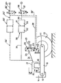
- the device according to the invention in the embodiment chosen and shown in the single figure, is applied to an industrial motor vehicle and comprises for each wheel (or wheel assembly of the vehicle) a suspension arm 10 (or an axle), one end of which receives the axis 11 of the wheel 12 and the other end of which is articulated at 13 to the chassis 14 of the vehicle (not shown) about an axis parallel to that of the wheel; the chassis 14 rests on said arm 10 by means of an air cushion 15.
- an additional metal spring can be used, placed between the arm 10 and the chassis.
- the cushion 15 essentially consists of a piston 16 (here secured to the arm), movable in an envelope 17 forming a cylinder (fixed to the chassis), mobile sealing means in the form of a bellows 18 being provided between piston and cylinder.
- the suspension also comprises an internal or external neutral point offset leveling valve 20, operating by translation or rotation of the valve body, or by modification of the length of the actuating rod, this valve 20 being controlled by a linkage 19 , articulated between the chassis and the suspension arm 10.
- the valve 20 is supplied at 21 by the compressed air source of the vehicle (not shown) and has an exhaust orifice 22 and a use orifice 23 connected by a pipe 24 inside the cushion 15. It is further provided with an orifice 25 for controlling the neutral point shift.
- This valve 20 in known manner, permanently adjusts the height of the cushion by supplying this cushion with air, or exhausting.
- the compressed air flow which it can allow to pass at the intake and respectively at the exhaust is preferably adjusted, by respective throttles at the intake and at the exhaust, to the minimum compatible with the necessary height regulation. at running.
- a reservoir 30 comprising a cylindrical body in which is disposed a movable partition 31 dividing this body into two chambers 32 and 33, without communication between them.
- the chamber 32 is connected to the interior of the cushion 15 by a pipe 34 of relatively large section, compatible with the large air flows to be passed between the chamber 32 and the cushion 15.
- the movable partition tank 30 can be produced for example by means of a pneumatic cylinder whose piston serves as a movable partition and where, if necessary, the rod has been removed and the rod bearing replaced by a closed cover. Its volume is defined so that the stroke of the piston (or movable partition 31) corresponds to the scanning of a volume capable of ensuring at the level of the suspension cushion 15 a desired height variation h between two leveling positions, in the absence of any air intake or exhaust of air by the leveling valve 20.
- the movable partition 31 can of course also be constituted by a flexible membrane which generally has a larger diametrical size and better sealing.
- the second chamber 33 of the reservoir 30 is connected by a pipe 35 to the outlet of a distributor 36 supplied with 37 by the source of compressed air from the vehicle.
- This distributor is adapted to put the chamber 33 in contact either with this source of compressed air or with the atmosphere or the exhaust.
- the outlet of the distributor 36 is connected by a pipe 38 to the neutral point offset orifice 25 of the leveling valve 20.
- the driver of the vehicle When the driver of the vehicle wishes to quickly lower the attitude of the vehicle to the low position corresponding to the passenger stop, it causes the chamber 33 of the tank to be exhausted by the control of the distributor 36 which allows the emptying of this room has atmosphere.
- the chassis of the vehicle lowers quickly from the height h, function of the ratio between the volume of the cushion 15 and the volume of the reservoir 30.
- the control of the distributor 36 actuates (via the line 38) the neutral point shifting device of the valve 20, to regulate the suspension around a low suspension position.
- the leveling valve simultaneously receiving the neutral point adjustment signal. ensuring a regulation of the height of the suspension around each of these positions.
- the chamber 32 can have a non-negligible minimum volume and capable of playing the role of an additional reservoir for the suspension cushion 15 during normal vehicle operation, this additional reservoir being enlarged in the low position of the vehicle suspension.
- the pipe 34 has a low pressure drop allowing rapid exchanges (in a few seconds) of compressed air between the chamber 32 (reduced to its minimum volume or not) and the interior of the suspension cushion 15. This low pressure drop is nevertheless capable of causing a damping effect in the event of a sudden variation in the internal volume of the pneumatic cushion 15 as a result of a relative displacement of the casing 17 and of the piston 16 consecutive to a bump or shock to the vehicle suspension.
- each suspension cushion 15 a set of leveling valve 20, of reservoir 30 and of distributor 36 with safety valves (not shown) to counter the burst of a suspension cushion. It is also possible to provide several suspension cushions (preferably symmetrically arranged with respect to the axis of the wheel or of the group of wheels to which they relate) for the same wheel or the same group of wheels or the same axle and which are simultaneously connected to the same set of leveling valve 20, tank 30 and distributor 36.
- more than one movable partition reserve such as 30 is put in place, the movement of each movable partition being independently ordered.
Landscapes
- Engineering & Computer Science (AREA)
- Mechanical Engineering (AREA)
- Vehicle Body Suspensions (AREA)
Abstract
Description
La présente invention se rapporte a un dispositif de changement de position d'assiette pour un véhicule à suspension pneumatique, en particulier pour un véhicule industriel destiné au transport des personnes.The present invention relates to a device for changing the attitude position for a vehicle with pneumatic suspension, in particular for an industrial vehicle intended for the transport of persons.
Dans les autobus urbains principalement, une préoccupation importante du concepteur consiste à faciliter l'accès des passagers, a leur montée et à leur descente du véhicule. Cela est obtenu par l'adoption d'un châssis peu encombrant en hauteur; cependant les limites mécaniques de construction ne permettent pratiquement pas d'obtenir le résultat souhaité sans recourir à l'affaissement et au relevage de la suspension du véhicule aux points d'arrêt de ce dernier.In urban buses mainly, an important concern of the designer consists in facilitating the access of passengers, when getting in and out of the vehicle. This is achieved by the adoption of a space-saving chassis in height; however, the mechanical construction limits practically do not allow the desired result to be obtained without resorting to the subsidence and lifting of the vehicle suspension at the latter's stopping points.
On connaît déjà divers dispositifs permettant ce mode de fonctionnement.Various devices are already known which allow this operating mode.
Dans certains de ces dispositifs, la hauteur des coussins de la suspension pneumatique est réglée au moyen d'une valve de nivellement, constituée d'un distributeur à commande mécanique à trois positions. Deux positions stables de l'assiette du véhicule, haute et basse, sont associées à deux points neutres de ce distributeur, positions autour desquelles le distributeur assure la régulation de l'assiette.In some of these devices, the height of the air suspension cushions is adjusted by means of a leveling valve, consisting of a mechanically operated distributor with three positions. Two stable positions of the attitude of the vehicle, high and low, are associated with two neutral points of this distributor, positions around which the distributor ensures the regulation of the attitude.
Une variante de cette solution est utilisée dans d'autres dispositifs: le distributeur est alors monté sur une embase pivotante à plusieurs positions, ce qui permet de décaler la position neutre de la valve de nivellement par rapport au châssis du véhicule.A variant of this solution is used in other devices: the distributor is then mounted on a pivoting base in several positions, which makes it possible to offset the neutral position of the leveling valve relative to the chassis of the vehicle.
Dans d'autres dispositifs de changement de position d'assiette, la suspension du véhicule utilise en plus des coussins pneumatiques des réservoirs complémentaires, associés à ceux-ci. Le réservoir complémentaire est isolé du coussin par une valve qui permet de vidanger ce dernier dans l'atmosphère, la position basse étant ainsi obtenue par appui sur les butées de suspension.In other attitude position change devices, the vehicle suspension uses, in addition to the air bags, additional reservoirs associated with them. The additional tank is isolated from the cushion by a valve which allows this the latter in the atmosphere, the low position being thus obtained by pressing on the suspension stops.
Dans cette position, la valve de nivellement permet le remplissage du réservoir à la pression maximale du circuit: ainsi, lorsque la liaison réservoir-coussin est rétablie, le véhicule est rapidement relevé à sa position haute.In this position, the leveling valve allows the filling of the tank to the maximum pressure of the circuit: thus, when the tank-cushion connection is re-established, the vehicle is quickly raised to its high position.
Les dispositifs connus présentent divers inconvénients. Pour les premiers cités, le faible débit ou l'amortissement de la valve de nivellement, nécessaire en position de roulage afin de réduire la consommation d'air, interdisent un abaissement ou un relevage rapide.The known devices have various drawbacks. For the first cities, the low flow or damping of the leveling valve, necessary in the driving position in order to reduce air consumption, prohibits lowering or rapid lifting.
Pour les derniers cités, la vidange totale du coussin à l'abaissement est source de forte consommation d'air, et entraîne un accroissement du travail fourni par le compresseur du véhicule. Le remplissage du réservoir complémentaire en position basse prolongée est ensuite à l'origine d'un dépassement important de l'assiette route, ce qui est source à la fois d'inconfort et de surconsommation d'air. De plus, si le stationnement du véhicule en position basse est de courte durée, le relèvement de la suspension ne s'effectue que partiellement, ce qui peut être à l'origine d'avaries mécaniques graves.For the latter mentioned, the total emptying of the lowering cushion is a source of high air consumption, and leads to an increase in the work provided by the vehicle compressor. The filling of the additional tank in the extended low position is then the cause of a significant overstepping of the road attitude, which is a source of both discomfort and overconsumption of air. In addition, if the vehicle is parked in the low position for a short period of time, the suspension will only be raised partially, which can cause serious mechanical damage.
La présente invention a pour objet un dispositif de changement d'assiette d'un véhicule à suspension pneumatique, permettant notamment le passage d'une hauteur de suspension haute à une hauteur de suspension correspondant à l'arrêt voyageurs, rapidement, sans pertes d'air dans les chambres de suspension et sans dépassement d'assiette de part et d'autre des deux positions prévues.The subject of the present invention is a device for changing the attitude of a vehicle with air suspension, allowing in particular the passage from a high suspension height to a suspension height corresponding to the passenger stop, quickly, without loss of air in the suspension chambers and without overflow on either side of the two positions provided.
L'invention a également pour objet un dispositif applicable à toute suspension pneumatique de véhicule, avec ou sans réservoirs additionnels, utilisant des composants pneumatiques classiques, et ne nécessitant pas des mises au point ou réglages délicats.The invention also relates to a device applicable to any pneumatic suspension of a vehicle, with or without additional tanks, using conventional pneumatic components, and not requiring delicate adjustments or adjustments.
Selon l'invention, le dispositif de changement de position d'assiette pour véhicule à suspension au moins partiellement pneumatique, cette suspension comportant au moins un coussin de suspension alimenté en air comprimé par l'intermédiaire d'une valve de nivellement, adaptée à réguler la position d'assiette du véhicule autour d'un point neutre et comprenant au moins un réservoir séparé en deux chambres par une cloison mobile et dont la première chambre est reliée audit coussin, est caractérisé en ce que la deuxième chambre est reliée à un distributeur adapté à la mettre en communication soit avec une source d'air comprimé dont la pression est suffisante pour faire réduire la première chambre à un volume minimal par déplacement de la cloison mobile, le coussin de suspension présentant alors un volume correspondant à la position normale de roulage du véhicule, soit avec l'atmosphère ou l'échappement, l'air contenu dans le coussin transitant alors en partie vers la première chambre et repoussant la cloison mobile en sens contraire jusqu'en fin de course, et en ce que la valve de nivellement comporte un dispositif de décalage de point neutre relié à la deuxième chambre par une canalisation de manière que la mise en pression de la chambre corresponde à un premier réglage du point neutre pour la position de roulage et que sa mise à l'air libre corresponde à un second réglage du point neutre pour la position basse ou d'arrêt qui est obtenue par l'abaissement de la pression consécutif au déplacement de la cloison mobile pour augmenter le volume de la première chambre.According to the invention, the attitude position change device for a vehicle with at least partially pneumatic suspension, this suspension comprising at least one suspension cushion supplied with compressed air by means of a leveling valve, adapted to regulate the attitude position of the vehicle around a neutral point and comprising at least one tank separated into two chambers by a movable partition and the first chamber of which is connected to said cushion, is characterized in that the second chamber is connected to a distributor adapted to put it in communication either with a compressed air source whose pressure is sufficient to reduce the first chamber to a minimum volume by displacement of the movable partition, the suspension cushion then having a volume corresponding to the normal rolling position of the vehicle, either with the atmosphere or the exhaust, the air contained in the cushion then partly passing through to the first chamber and pushing the movable partition in opposite directions until the end of travel, and in that the leveling valve comprises a neutral point shifting device connected to the second chamber by a pipe so that the pressurization of the chamber corresponds to a first adjustment of the neutral point for the rolling position and that its venting corresponds to a second adjustment of the neutral point for the low or off position which is obtained by lowering the pressure following the displacement of the movable partition to increase the volume of the first chamber.
L'invention prévoit également de compléter le dispositif par un ou plusieurs autres réservoirs supplémentaires permettant de conférer à la suspension une ou plusieurs autres positions. A cet effet, il comporte au moins un autre réservoir à cloison mobile analogue au premier cité et relié de même directement au coussin de suspension et à une source d'air comprimé par un autre distributeur, pour déplacer ledit coussin entre la position de roulage et une autre position de nivellement de suspension et le dispositif de décalage de point neutre est relié à la deuxième chambre dudit autre réservoir par une canalisation de façon que la mise en pression de ladite deuxième chambre corresponde à un troisième réglage de point neutre obtenu à la suite de la réduction de volume de la première chambre dudit autre réservoir tandis que la mise à l'échappement de ladite deuxième chambre correspond au réglage de la suspension par le réservoir.The invention also provides for supplementing the device with one or more other additional reservoirs making it possible to give the suspension one or more other positions. To this end, it comprises at least one other tank with a movable partition similar to the first city and likewise connected directly to the suspension cushion and to a source of compressed air by another distributor, for moving said cushion between the rolling position and another suspension leveling position and the neutral point shifting device is connected to the second chamber of said other tank by a pipe so that the pressure in said second chamber corresponds to a third neutral point adjustment obtained after the reduction in volume of the first chamber of said other tank while the exhausting of said second chamber corresponds to the adjustment of the suspension by the tank.
La valve de nivellement est apte à laisser transiter à l'admission et respectivement à l'échappement un débit d'air comprimé qui est ajusté au voisinage du minimum compatible avec la régulation de hauteur nécessaire au cours du roulage du véhicule tandis que la liaison entre le coussin de suspension et la première chambre est réalisée par un passage de section importante compatible avec les débits à laisser transiter entre la première chambre et le coussin de suspension.The leveling valve is capable of letting a compressed air flow pass through the intake and respectively through the exhaust, which is adjusted to the vicinity of the minimum compatible with the height regulation required during the running of the vehicle while the connection between the suspension cushion and the first chamber is produced by a passage of large cross section compatible with the flow rates to be allowed to pass between the first chamber and the suspension cushion.
Selon un autre mode de réalisation avantageux de l'invention, la liaison de section importante entre le coussin de suspension et la première chambre peut être ajustée de manière à produire néanmoins un effet d'amortissement en cas de variation brutale de volume du coussin de suspension et la première chambre peut présenter un volume minimal apte à jouer le rôle de réservoir additionnel pour le coussin de suspension.According to another advantageous embodiment of the invention, the large cross-section connection between the suspension cushion and the first chamber can be adjusted so as to nevertheless produce a damping effect in the event of a sudden change in the volume of the suspension cushion and the first chamber may have a minimum volume capable of playing the role of additional reservoir for the suspension cushion.
Les caractéristiques et avantages de l'invention ressortiront d'ailleurs mieux de la description suivante, donnée uniquement à titre d'exemple, en référence à la figure unique du dessin annexé qui illustre très schématiquement une forme de réalisation du dispositif selon l'invention.The characteristics and advantages of the invention will moreover emerge better from the following description, given solely by way of example, with reference to the single figure of the appended drawing which very schematically illustrates an embodiment of the device according to the invention.
Le dispositif selon l'invention, dans la forme de réalisation choisie et représentée à la figure unique est appliqué à un véhicule automobile industriel et comporte pour chaque roue (ou ensemble de roue du véhicule) un bras de suspension 10 (ou un essieu), dont une extrémité reçoit l'axe 11 de la roue 12 et dont l'autre extrémité est articulée en 13 au châssis 14 du véhicule (non représenté) autour d'un axe parallèle à celui de la roue; le châssis 14 repose sur ledit bras 10 par l'intermédiaire d'un coussin pneumatique 15. Dans certains dispositions de suspension, un ressort métallique supplémentaire peut être utilisé, placé entre le bras 10 et le châssis.The device according to the invention, in the embodiment chosen and shown in the single figure, is applied to an industrial motor vehicle and comprises for each wheel (or wheel assembly of the vehicle) a suspension arm 10 (or an axle), one end of which receives the
Le coussin 15 consiste essentiellement en un piston 16 (ici solidaire du bras), mobile dans une enveloppe 17 formant cylindre (fixée au châssis), des moyens d'étanchéité mobiles sous forme d'un soufflet 18 étant prévus entre piston et cylindre. La suspension comporte également une valve de nivellement à décalage de point neutre 20 interne ou externe, fonctionnant par translation ou rotation du corps de valve, ou par modification de la longueur de la tige d'actionnement, cette valve 20 étant commandée par une tringlerie 19, articulée entre le châssis et le bras de suspension 10. La valve 20 est alimentée en 21 par la source d'air comprimé du véhicule (non représentée) et présente un orifice d'échappement 22 et un orifice d'utilisation 23 relié par une canalisation 24 à l'intérieur du coussin 15. Elle est en outre munie d'un orifice 25 de commande de décalage de point neutre.The cushion 15 essentially consists of a piston 16 (here secured to the arm), movable in an
Cette valve 20, de manière connue, assure en permanence le réglage de la hauteur du coussin par alimentation de ce coussin en air, ou mise à l'échappement. Le débit d'air comprimé qu'elle peut laisser transiter à l'admission et respectivement à l'échappement est de préférence ajusté, par des étranglements respectifs à l'admission et à l'échappement, au minimum compatible avec la régulation de hauteur nécessaire au cours du roulage.This
La suspension ainsi réalisée et par ailleurs connue en soi, est complétée selon l'invention, par un réservoir 30 comportant un corps cylindrique dans lequel est disposée une cloison mobile 31 divisant ce corps en deux chambres 32 et 33, sans communication entre elles. La chambre 32 est reliée à l'intérieur du coussin 15 par une tuyauterie 34 de relativement forte section, compatible avec les débits d'air importants à faire transiter entre la chambre 32 et le coussin 15.The suspension thus produced and also known per se, is completed according to the invention, by a
Le réservoir 30 à cloison mobile peut être réalisé par exemple au moyen d'un vérin pneumatique dont le piston sert de cloison mobile et où, le cas échéant, la tige a été supprimée et le palier de tige remplacé par un couvercle fermé. Son volume est défini de telle sorte que la course du piston (ou cloison mobile 31) corresponde au balayage d'un volume propre à assurer au niveau du coussin de suspension 15 une variation de hauteur h désirée entre deux positions de nivellement, en l'absence de toute admission d'air ou échappement d'air par la valve de nivellement 20. La cloison mobile 31 peut bien entendu également être constituée par une membrane souple qui présente en général un plus grand encombrement diamétral et une meilleure étanchéité.The
Pour le déplacement de la cloison mobile 31, la seconde chambre 33 du réservoir 30 est reliée par une canalisation 35 à la sortie d'un distributeur 36 alimenté en 37 par la source d'air comprimé du véhicule. Ce distributeur est adapté à mettre la chambre 33 en relation soit avec cette source d'air comprimé soit avec l'atmosphère ou l'échappement.For the displacement of the movable partition 31, the
Par ailleurs, la sortie du distributeur 36 est reliée par une canalisation 38 à l'orifice 25 de décalage de point neutre de la valve de nivellement 20.Furthermore, the outlet of the
Le fonctionnement du dispositif selon l'invention est le suivant:The operation of the device according to the invention is as follows:
Lorsque le conducteur du véhicule désire abaisser rapidement l'assiette du véhicule en position basse correspondant à l'arrêt- voyageurs, il provoque la mise à l'échappement de la chambre 33 du réservoir par la commande du distributeur 36 qui permet la vidange de cette chambre a l'atmosphère. L'air sous pression du coussin 15, s'échappant par la tuyauterie 34, remplit la chambre 32 du réservoir 30, dont la cloison mobile 31 se déplace jusqu'à fin de course en abaissant ainsi considérablement la pression de suspension régnant dans le coussin 15. Le châssis du véhicule s'abaisse rapidement de la hauteur h, fonction du rapport entre le volume du coussin 15 et du volume du réservoir 30.When the driver of the vehicle wishes to quickly lower the attitude of the vehicle to the low position corresponding to the passenger stop, it causes the
Simultanément, la commande du distributeur 36 actionne (par la canalisation 38) le dispositif de décalage de point neutre de la valve 20, pour assurer la régulation de la suspension autour d'une position basse de suspension.Simultaneously, the control of the
Pour faire remonter l'assiette du véhicule en position normale de roulage, par commande inverse du distributeur 36, de l'air sous pression est envoyé dans la chambre 33 du réservoir. L'air contenu dans la chambre 32 est refou'é vers le coussin 15 ce qui augmente sa pression et par voie de conséque-.ce sa hauteur de h, tandis que le point neutre de la valve de nivellement 20 est ramené au réglage correspondant à la position haute de suspension correspondante, par actionnement du dispositif de décalage de ce point neutre par la commande du distributeur 36, via la canalisation 38.To raise the attitude of the vehicle to the normal driving position, by reverse control of the
Grâce au dispcsitif qui vient d'être décrit, il est donc possible de réaliser très rapidement le passage d'une position haute de la suspension à une position basse, et vice versa, la valve de nivellement recevant simultanément le signal de réglage de point neutre assurant une régulation de la hauteur de la suspension autour de chacune de ces positions.Thanks to the device which has just been described, it is therefore possible very quickly to pass from a high position of the suspension to a low position, and vice versa, the leveling valve simultaneously receiving the neutral point adjustment signal. ensuring a regulation of the height of the suspension around each of these positions.
Au cours de ces réglages rapides de l'assiette de la suspension pneumatique, pratiquement aucun débit d'air comprimé ne transite par la valve de nivellement 20 qui présente par ailleurs, comme on l'a mentionné précédemment, une faible capacité de débit à l'admission et à l'échappement et qui doit en général être alimentée en air sec et filtré pour éviter la dégradation du circuit et des chambres de suspension pneumatiques par des condensations éventuelles. Dans le dispositif selon l'invention, il est possible pour économiser l'air sec relativement onéreux, d'utiliser de l'air comprimé ordinaire pour alimenter le distributeur 36.During these rapid adjustments of the air suspension base, practically no flow of compressed air passes through the
La chambre 32 peut présenter un volume minimal non négligeable et apte à jouer le rôle d'un réservoir additionnel pour le coussin de suspension 15 pendant la marche normale du véhicule, ce réservoir additionnel étant agrandi en position basse de la suspension du véhicule. La canalisation 34 présente une perte de charge faible permettant des échanges rapides (en quelques secondes) d'air comprimé entre la chambre 32 (réduite à son volume minimal ou non) et l'intérieur du coussin de suspension 15. Cette perte de charge faible est néanmoins capable de provoquer un effet d'amortissement en cas de variation brutale du volume intérieur du coussin pneumatique 15 par suite d'un déplacement relatif de l'enveloppe 17 et du piston 16 consécutif à un cahot ou à un choc sur la suspension du véhicule.The chamber 32 can have a non-negligible minimum volume and capable of playing the role of an additional reservoir for the suspension cushion 15 during normal vehicle operation, this additional reservoir being enlarged in the low position of the vehicle suspension. The
Pour l'équipement d'un véhicule selon l'invention, on peut prévoir pour chaque coussin de suspension 15 un ensemble de valve de nivellement 20, de réservoir 30 et de distributeur 36 avec des valves de sécurité (non représentées) pour parer à l'éclatement d'un coussin de suspension. On peut également prévoir plusieurs coussins de suspension (de préférence symétriquement disposés par rapport à l'axe de la roue ou du groupe de roues auxquels ils se rapportent) pour une même roue ou un même groupe de roues ou un même essieu et qui sont simultanément reliés à un même ensemble de valve de nivellement 20, de réservoir 30 et de distributeur 36.For the equipment of a vehicle according to the invention, it is possible to provide for each suspension cushion 15 a set of
Pour certaines applications particulières, il peut être nécessaire de réaliser plus de deux positions de nivellement: dans ce cas, selon l'invention, on met en place plus d'un réservcir à cloison mobile tel que 30, le mouvement de chaque cloison mobile étant commandé de façon indépendante.For certain particular applications, it may be necessary to make more than two leveling positions: in this case, according to the invention, more than one movable partition reserve such as 30 is put in place, the movement of each movable partition being independently ordered.
Une telle disposition est représentée er traits interrompus sur la figure unique, les éléments supplémentaires recevant la même référence numérique que leurs homologues déjà décrits, affectée de l'indice prime.Such an arrangement is represented by broken lines in the single figure, the additional elements receiving the same reference number as their counterparts already described, assigned the prime index.
Claims (5)
Applications Claiming Priority (2)
| Application Number | Priority Date | Filing Date | Title |
|---|---|---|---|
| FR8416047 | 1984-10-19 | ||
| FR8416047A FR2572030B1 (en) | 1984-10-19 | 1984-10-19 | PLATE CHANGE DEVICE FOR AIR SUSPENSION VEHICLE, PARTICULARLY FOR INDUSTRIAL VEHICLE FOR THE TRANSPORT OF PERSONS |
Publications (2)
| Publication Number | Publication Date |
|---|---|
| EP0181794A1 true EP0181794A1 (en) | 1986-05-21 |
| EP0181794B1 EP0181794B1 (en) | 1988-02-17 |
Family
ID=9308832
Family Applications (1)
| Application Number | Title | Priority Date | Filing Date |
|---|---|---|---|
| EP19850401974 Expired EP0181794B1 (en) | 1984-10-19 | 1985-10-10 | Height-regulating arrangement for a vehicle with a pneumatic suspension, particularly for an industrial vehicle carrying people |
Country Status (3)
| Country | Link |
|---|---|
| EP (1) | EP0181794B1 (en) |
| DE (1) | DE3561618D1 (en) |
| FR (1) | FR2572030B1 (en) |
Cited By (4)
| Publication number | Priority date | Publication date | Assignee | Title |
|---|---|---|---|---|
| EP0459095A1 (en) * | 1990-04-27 | 1991-12-04 | MAN Nutzfahrzeuge Aktiengesellschaft | Omnibus especially with low platform |
| EP0530366A1 (en) * | 1991-02-27 | 1993-03-10 | Isuzu Motors Limited | Vehicle height adjusting device |
| WO2001087649A1 (en) * | 2000-05-15 | 2001-11-22 | Sjoelund Anders | Rear end vehicle spring |
| WO2014202631A1 (en) * | 2013-06-20 | 2014-12-24 | Siemens Ag Österreich | Pneumatic-suspension unit for a rail vehicle |
Families Citing this family (1)
| Publication number | Priority date | Publication date | Assignee | Title |
|---|---|---|---|---|
| CN103075509B (en) * | 2013-01-30 | 2015-09-30 | 江苏柳工机械有限公司 | The power gear shift speed change control valve of gear individual buffer |
Citations (6)
| Publication number | Priority date | Publication date | Assignee | Title |
|---|---|---|---|---|
| US1869285A (en) * | 1931-02-09 | 1932-07-26 | George H Taber | Vehicle body suspension |
| DE1122386B (en) * | 1959-12-24 | 1962-01-18 | Boge Gmbh | Control for hydraulic-pneumatic suspensions, especially of motor vehicles |
| FR2125217A1 (en) * | 1971-02-19 | 1972-09-29 | Saviem | |
| FR2152351A1 (en) * | 1971-09-06 | 1973-04-27 | Citroen Sa | |
| DE2604809A1 (en) * | 1976-02-07 | 1977-08-11 | Bayerische Motoren Werke Ag | Variable setting car suspension - with adjustable mounting for spring to alter damping frequency and riding height |
| FR2526723A1 (en) * | 1982-05-12 | 1983-11-18 | Renault Vehicules Ind | Hydro pneumatic suspension for vehicle - comprises pressure transmission piston which separates pressurised gas and liquid circuits |
-
1984
- 1984-10-19 FR FR8416047A patent/FR2572030B1/en not_active Expired
-
1985
- 1985-10-10 EP EP19850401974 patent/EP0181794B1/en not_active Expired
- 1985-10-10 DE DE8585401974T patent/DE3561618D1/en not_active Expired
Patent Citations (6)
| Publication number | Priority date | Publication date | Assignee | Title |
|---|---|---|---|---|
| US1869285A (en) * | 1931-02-09 | 1932-07-26 | George H Taber | Vehicle body suspension |
| DE1122386B (en) * | 1959-12-24 | 1962-01-18 | Boge Gmbh | Control for hydraulic-pneumatic suspensions, especially of motor vehicles |
| FR2125217A1 (en) * | 1971-02-19 | 1972-09-29 | Saviem | |
| FR2152351A1 (en) * | 1971-09-06 | 1973-04-27 | Citroen Sa | |
| DE2604809A1 (en) * | 1976-02-07 | 1977-08-11 | Bayerische Motoren Werke Ag | Variable setting car suspension - with adjustable mounting for spring to alter damping frequency and riding height |
| FR2526723A1 (en) * | 1982-05-12 | 1983-11-18 | Renault Vehicules Ind | Hydro pneumatic suspension for vehicle - comprises pressure transmission piston which separates pressurised gas and liquid circuits |
Cited By (5)
| Publication number | Priority date | Publication date | Assignee | Title |
|---|---|---|---|---|
| EP0459095A1 (en) * | 1990-04-27 | 1991-12-04 | MAN Nutzfahrzeuge Aktiengesellschaft | Omnibus especially with low platform |
| EP0530366A1 (en) * | 1991-02-27 | 1993-03-10 | Isuzu Motors Limited | Vehicle height adjusting device |
| EP0530366A4 (en) * | 1991-02-27 | 1993-04-07 | Isuzu Motors Limited | Vehicle height adjusting device |
| WO2001087649A1 (en) * | 2000-05-15 | 2001-11-22 | Sjoelund Anders | Rear end vehicle spring |
| WO2014202631A1 (en) * | 2013-06-20 | 2014-12-24 | Siemens Ag Österreich | Pneumatic-suspension unit for a rail vehicle |
Also Published As
| Publication number | Publication date |
|---|---|
| DE3561618D1 (en) | 1988-03-24 |
| FR2572030A1 (en) | 1986-04-25 |
| FR2572030B1 (en) | 1988-12-09 |
| EP0181794B1 (en) | 1988-02-17 |
Similar Documents
| Publication | Publication Date | Title |
|---|---|---|
| FR2566716A1 (en) | SUSPENSION FOR MOTOR VEHICLE | |
| FR2467719A1 (en) | FLUID SUSPENSION ASSEMBLY, IN PARTICULAR FOR MOTOR VEHICLES | |
| FR2822918A1 (en) | PNEUMATIC PILOT DEVICE FOR AUTOMATIC INFLATION-DEFLATION OF A CONTAINMENT CAPACITY OF A GAS FLUID UNDER RELATIVE PRESSURE | |
| EP0181794B1 (en) | Height-regulating arrangement for a vehicle with a pneumatic suspension, particularly for an industrial vehicle carrying people | |
| FR2635729A1 (en) | DEVICE FOR CORRECTING THE PLATE OF A MOTOR VEHICLE | |
| FR2566338A1 (en) | VEHICLE SUSPENSION WITH HEIGHT ADJUSTMENT | |
| FR2564786A1 (en) | VEHICLE SUSPENSION APPARATUS | |
| FR2687350A1 (en) | EXHAUST VALVE AND FLUID SUPPLY VALVE, IN PARTICULAR LEVELING VALVE FOR PNEUMATIC SUSPENSION AND SUSPENSION SYSTEM USING SUCH VALVES. | |
| EP1437242B1 (en) | Hydraulic suspension system | |
| FR1465751A (en) | Brakes for rail vehicles | |
| EP0440083B1 (en) | Apparatus for regulation of the stiffness of a tyre and vehicle provided with such an apparatus | |
| EP0663308B1 (en) | Suspension for a motor vehicle | |
| CH616116A5 (en) | Pneumatic directional control valve for railway braking | |
| FR2555775A1 (en) | DEVICE FOR ACTUATING TWO VALVES THAT CAN BE ACTIVELY INTERDEPENDENT | |
| FR2608539A1 (en) | BRAKING SYSTEM FOR A MOTOR VEHICLE WITH CONTROLLED DISTRIBUTION | |
| BE1001764A3 (en) | CHASSIS HEIGHT CONTROL SYSTEM FOR A PNEUMATIC SUSPENSION VEHICLE. | |
| FR2503055A1 (en) | Adjustable height hydraulic suspension for motor vehicles - uses combined height adjuster and damper unit controlled by electrically operated hydraulic pressure fluid distributor valve | |
| FR2640552A3 (en) | Device for adjusting the height with respect to the ground of a road vehicle chassis provided with an axle which can be raised | |
| FR2655594A1 (en) | System for rapid automatic return to the normal level of use for pneumatic suspension | |
| WO1999050081A1 (en) | Suspension and damping device with two suspension-damper combinations | |
| FR2485459A1 (en) | Dual circuit pneumatic car brake system - is load adaptive and has front brake force modulated w.r.t. rear brake force | |
| BE1001230A3 (en) | A marine propulsion device assisted steering, shift assisted steering control and gas. | |
| FR2651184A1 (en) | SUPPORT PIECE FOR SUSPENSION ELEMENT. | |
| FR2705741A1 (en) | Boosted pneumatic control device | |
| EP0873894B1 (en) | Hydropneumatic suspension for a set of wheels of a running gear for a motor vehicle |
Legal Events
| Date | Code | Title | Description |
|---|---|---|---|
| PUAI | Public reference made under article 153(3) epc to a published international application that has entered the european phase |
Free format text: ORIGINAL CODE: 0009012 |
|
| AK | Designated contracting states |
Kind code of ref document: A1 Designated state(s): BE DE FR GB IT LU NL |
|
| 17P | Request for examination filed |
Effective date: 19860618 |
|
| 17Q | First examination report despatched |
Effective date: 19870507 |
|
| GRAA | (expected) grant |
Free format text: ORIGINAL CODE: 0009210 |
|
| AK | Designated contracting states |
Kind code of ref document: B1 Designated state(s): BE DE FR GB IT LU NL |
|
| ITF | It: translation for a ep patent filed |
Owner name: JACOBACCI & PERANI S.P.A. |
|
| GBT | Gb: translation of ep patent filed (gb section 77(6)(a)/1977) | ||
| REF | Corresponds to: |
Ref document number: 3561618 Country of ref document: DE Date of ref document: 19880324 |
|
| PG25 | Lapsed in a contracting state [announced via postgrant information from national office to epo] |
Ref country code: LU Free format text: LAPSE BECAUSE OF NON-PAYMENT OF DUE FEES Effective date: 19881031 |
|
| PLBE | No opposition filed within time limit |
Free format text: ORIGINAL CODE: 0009261 |
|
| STAA | Information on the status of an ep patent application or granted ep patent |
Free format text: STATUS: NO OPPOSITION FILED WITHIN TIME LIMIT |
|
| 26N | No opposition filed | ||
| ITTA | It: last paid annual fee | ||
| PGFP | Annual fee paid to national office [announced via postgrant information from national office to epo] |
Ref country code: DE Payment date: 19940914 Year of fee payment: 10 |
|
| PGFP | Annual fee paid to national office [announced via postgrant information from national office to epo] |
Ref country code: GB Payment date: 19940915 Year of fee payment: 10 |
|
| PGFP | Annual fee paid to national office [announced via postgrant information from national office to epo] |
Ref country code: BE Payment date: 19940916 Year of fee payment: 10 |
|
| PGFP | Annual fee paid to national office [announced via postgrant information from national office to epo] |
Ref country code: FR Payment date: 19940919 Year of fee payment: 10 |
|
| PGFP | Annual fee paid to national office [announced via postgrant information from national office to epo] |
Ref country code: NL Payment date: 19941031 Year of fee payment: 10 |
|
| PG25 | Lapsed in a contracting state [announced via postgrant information from national office to epo] |
Ref country code: GB Effective date: 19951010 |
|
| PG25 | Lapsed in a contracting state [announced via postgrant information from national office to epo] |
Ref country code: BE Effective date: 19951031 |
|
| BERE | Be: lapsed |
Owner name: RENAULT VEHICULES INDUSTRIELS Effective date: 19951031 |
|
| PG25 | Lapsed in a contracting state [announced via postgrant information from national office to epo] |
Ref country code: NL Effective date: 19960501 |
|
| GBPC | Gb: european patent ceased through non-payment of renewal fee |
Effective date: 19951010 |
|
| PG25 | Lapsed in a contracting state [announced via postgrant information from national office to epo] |
Ref country code: FR Effective date: 19960628 |
|
| NLV4 | Nl: lapsed or anulled due to non-payment of the annual fee |
Effective date: 19960501 |
|
| PG25 | Lapsed in a contracting state [announced via postgrant information from national office to epo] |
Ref country code: DE Effective date: 19960801 |
|
| REG | Reference to a national code |
Ref country code: FR Ref legal event code: ST |