EP0180824A2 - Device for sealed connection of two pipes with smooth cylindrical ends - Google Patents
Device for sealed connection of two pipes with smooth cylindrical ends Download PDFInfo
- Publication number
- EP0180824A2 EP0180824A2 EP85113106A EP85113106A EP0180824A2 EP 0180824 A2 EP0180824 A2 EP 0180824A2 EP 85113106 A EP85113106 A EP 85113106A EP 85113106 A EP85113106 A EP 85113106A EP 0180824 A2 EP0180824 A2 EP 0180824A2
- Authority
- EP
- European Patent Office
- Prior art keywords
- sealing
- pipes
- central web
- wall sections
- sleeve
- Prior art date
- Legal status (The legal status is an assumption and is not a legal conclusion. Google has not performed a legal analysis and makes no representation as to the accuracy of the status listed.)
- Granted
Links
Images
Classifications
-
- F—MECHANICAL ENGINEERING; LIGHTING; HEATING; WEAPONS; BLASTING
- F16—ENGINEERING ELEMENTS AND UNITS; GENERAL MEASURES FOR PRODUCING AND MAINTAINING EFFECTIVE FUNCTIONING OF MACHINES OR INSTALLATIONS; THERMAL INSULATION IN GENERAL
- F16L—PIPES; JOINTS OR FITTINGS FOR PIPES; SUPPORTS FOR PIPES, CABLES OR PROTECTIVE TUBING; MEANS FOR THERMAL INSULATION IN GENERAL
- F16L21/00—Joints with sleeve or socket
- F16L21/002—Sleeves or nipples for pipes of the same diameter; Reduction pieces
- F16L21/005—Sleeves or nipples for pipes of the same diameter; Reduction pieces made of elastic material, e.g. partly or completely surrounded by clamping devices
-
- F—MECHANICAL ENGINEERING; LIGHTING; HEATING; WEAPONS; BLASTING
- F16—ENGINEERING ELEMENTS AND UNITS; GENERAL MEASURES FOR PRODUCING AND MAINTAINING EFFECTIVE FUNCTIONING OF MACHINES OR INSTALLATIONS; THERMAL INSULATION IN GENERAL
- F16L—PIPES; JOINTS OR FITTINGS FOR PIPES; SUPPORTS FOR PIPES, CABLES OR PROTECTIVE TUBING; MEANS FOR THERMAL INSULATION IN GENERAL
- F16L17/00—Joints with packing adapted to sealing by fluid pressure
- F16L17/02—Joints with packing adapted to sealing by fluid pressure with sealing rings arranged between outer surface of pipe and inner surface of sleeve or socket
- F16L17/04—Joints with packing adapted to sealing by fluid pressure with sealing rings arranged between outer surface of pipe and inner surface of sleeve or socket with longitudinally split or divided sleeve
Definitions
- the invention relates to a device for the sealed connection of two tubes with smooth cylindrical ends, with a sealing collar contractible by a clamp band, which on its inner circumference has a centrally arranged, radially inwardly projecting, annular web as a stop for the pipe ends to be inserted and their outer edge areas has annular sealing lips, with a radially outwardly tapered inner wall section extending from both sides of the central web.
- the invention is based on the object of developing a device of the type described at the outset in such a way that that additional sealing areas are created and the inserted pipe ends are better held in the axial direction.
- the radially outwardly tapered inner wall sections each include an angle of inclination with the (elongated) longitudinal axis of the device of at most 20 °.
- the inserted pipe ends are advantageously sealed not only in the area of the sealing lips, but also on both sides of the central web by the pressed-in inner wall sections with a relatively large axial length, which also means that the inserted pipe ends are held in the sealing sleeve in the axial direction is considerably improved over the prior art.
- This advantageously also allows the width of the sealing collar to be reduced, which in turn leads to an economical solution due to the material savings.
- these two additional sealing areas are effective independently of the sealing lips.
- the sealing function of these additional sealing areas is retained even if the pipe ends are not perfectly perpendicular to the pipe axis, but rather run obliquely to it.
- the slight inclination of the two inner wall sections on both sides of the central web ensures that they cannot exert any outward thrust on the pipe ends when contracting the sealing sleeve, as is the case with the prior art explained at the beginning.
- Another advantage of the invention is that the pipe ends are well guided through the slightly beveled inner wall sections when inserted into the sealing sleeve.
- the radially outwardly tapered inner wall sections extend from the central web to the innermost sealing lip, there is advantageously the possibility of increasing the axial length of the additional ring-shaped sealing areas by correspondingly contracting the sealing sleeve.
- FIG. 2 denote the smooth cylindrical ends of two pipes to be connected in a sealed manner, with the same outside and inside diameters.
- These pipes 1, 2 can be steel or cast iron sewage pipes.
- the device 3 which has a sealing collar 4 made of elastomeric material and a clamp band 5, which serves to clamp the sealing collar 4, is used for the sealed connection of these two pipes 1, 2.
- the clamp band 5 which is preferably made of thin-walled stainless steel sheet, is provided with two radially outwardly projecting bevels which can be pulled against one another in a known manner by means of screws in order to reduce the inside diameter of the clamp band. These parts of the clamp band 5 are not shown since they are known.
- the sealing collar 4 encompassed by the clamp band 5 has two annular sealing lips 6, 7 on its inner two outer edge regions and a centrally arranged, radially inwardly projecting, annular web 8, which serves as a stop for the two pipe ends 9, 10 to be inserted .
- a radially outwardly tapered inner wall section 11 extends between each side of the web 8 and each innermost sealing lip 7.
- the angle of inclination cK of these inner wall sections 11 with respect to the elongated longitudinal axis 12 of the device 3 is 15 ° ⁇ 1 ° in the exemplary embodiment.
- the sealing lips 6, 7 are bent inwards and the inclined inner wall sections 11 serve as guides for the tube ends until the tube ends 9, 10 on the annular web Strike 8.
- the sealing sleeve 4 is dimensioned taking into account the fluctuating outer diameter of the tubes 1, 2 so that the tube ends 9, 10 either come to lie directly in the corners 14 (FIG. 1) or somewhat radially inward from these corners 14. It is understood that the sealing sleeve 4 is in the relaxed state in this assembly phase.
- the clamp band 5 is contracted in the circumferential direction by means of the screws, not shown, and the sealing sleeve 4 is thereby preloaded radially inwards.
Abstract
Description
Die Erfindung bezieht sich auf eine Vorrichtung zur abgedichteten Verbindung von zwei Rohren mit glattzylindrischen Enden, mit einer durch ein Schellenband kontraktierbaren Dichtmanschette, die an ihrem Innenumfang einen mittig angeordneten, radial nach innen ragenden, ringförmigen Steg als Anschlag für die einzusteckenden Rohr-Stirnenden und an ihren Außenrandbereichen ringförmige Dichtlippen aufweist, wobei sich von beiden Seiten des mittigen Stegs axial nach außen jeweils ein radial nach außen abgeschrägter Innenwandabschnitt erstreckt.The invention relates to a device for the sealed connection of two tubes with smooth cylindrical ends, with a sealing collar contractible by a clamp band, which on its inner circumference has a centrally arranged, radially inwardly projecting, annular web as a stop for the pipe ends to be inserted and their outer edge areas has annular sealing lips, with a radially outwardly tapered inner wall section extending from both sides of the central web.
Bei einer bekannten Vorrichtung der obigen Bauart erfolgt die Abdichtung der eingesteckten Rohre ausschließlich durch die ringförmigen Dichtlippen, was sich in der Praxis als nachteilig herausstellt. Außerdem besteht bei dieser bekannten Vorrichtung die Gefahr, daß beim Spannen des Schellenbandes durch die relativ stark nach außen abgeschrägten Innenwandabschnitte der Dichtmanschette (der Neigungswinkel dieser Innenwandabschnitte zur verlängerten Hauptachse beträgt mehr als 45°) auf die Rohr-Stirnenden eine axial nach außen gerichtete Schubkraft ausgeübt wird, was sich vor allem bei relativ schmalen Dichtmanschetten als äußerst nachteilig auswirkt. Die durch die kontraktierte Dichtmanschette auf die beiden Rohrenden ausgeübten Haltekräfte können dann nämlich ungenügend werden.In a known device of the above type, the inserted tubes are sealed exclusively by the annular sealing lips, which in practice turns out to be disadvantageous. Furthermore, with this known device is the risk that during the tensioning of the S chellenbandes by the relatively strong outwardly tapered inner wall sections of the sealing sleeve to the pipe end faces (the inclination angle of the inner wall portions to the extended main axis of more than 45 °) has an axially outwardly directed thrust force is exercised, which has an extremely disadvantageous effect, particularly in the case of relatively narrow sealing sleeves. The holding forces exerted on the two pipe ends by the contracted sealing sleeve can then become insufficient.
Der Erfindung liegt die Aufgabe zugrunde, eine Vorrichtung der eingangs bezeichneten Bauart derart weiterzubilden, daß zusätzliche Dichtbereiche geschaffen werden und die eingesteckten Rohrenden in axialer Richtung besser gehalten sind.The invention is based on the object of developing a device of the type described at the outset in such a way that that additional sealing areas are created and the inserted pipe ends are better held in the axial direction.
Diese Aufgabe wird erfindungsgemäß dadurch gelöst, daß zur Ausbildung von zusätzlichen ringförmigen Dichtbereichen neben jeder Seite des mittigen Stegs die radial nach außen abgeschrägten Innenwandabschnitte jeweils einen Neigungswinkel mit der (verlängerten) Längsachse der Vorrichtung von höchstens 20° einschließen. Bei kontraktierter Dichtmanschette werden dadurch vorteilhaft die eingesteckten Rohrenden nicht nur im Bereich der Dichtlippen, sondern zusätzlich auch zu beiden Seiten des mittigen Stegs durch die angepreßten Innenwandabschnitte mit relativ großer axialer Länge abgedichtet, wodurch zugleich auch die Halterung der eingesteckten Rohrenden in der Dichtmanschette in axialer Richtung gegenüber dem Stand der Technik beträchtlich verbessert wird. Vorteilhaft kann man dadurch auch die Breite der Dichtmanschette reduzieren, was wiederum aufgrund der Materialeinsparung zu einer wirtschaftlichen Lösung führt. Besonders zu erwähnen ist, daß diese beiden zusätzlichen Dichtbereiche unabhängig von den Dichtlippen wirksam sind. Die Dichtfunktion dieser zusätzlichen Dichtbereiche bleibt auch dann erhalten, wenn die Rohr-Stirnenden nicht einwandfrei senkrecht zur Rohrachse ausgebildet sind, sondern schräg zu dieser verlaufen. Schließlich ist durch die geringfügige Neigung der beiden Innenwandabschnitte zu beiden Seiten des mittigen Stegs gewährleistet, daß diese bei der Kontraktierung der Dichtmanschette keine nach außen gerichtete Schubkraft auf die Rohrenden ausüben können, wie dies bei dem eingangs erläuterten Stand der Technik der Fall ist. Ein anderer Vorteil der Erfindung besteht darin, daß die Rohrenden beim Einstecken in die Dichtmanschette durch die schwach abgeschrägten Innenwandabschnitte gut geführt werden. Dabei ist es zweckmäßig, wenn im entspannten Zustand der Dichtmanschette die Rohr-Stirnenden jeweils in der Ecke zwischen dem Steg und dem abgeschrägten Innenwandabschnitt oder etwas radial von dieser Ecke nach innen versetzt zum Liegen kommen. Mögliche Maß-Toleranzen bei den zu verbindenden Rohren können einfach durch stärkeres Verspannen des Schellenbandes ausgeglichen werden.This object is achieved in that in order to form additional annular sealing areas next to each side of the central web, the radially outwardly tapered inner wall sections each include an angle of inclination with the (elongated) longitudinal axis of the device of at most 20 °. In the case of a contracted sealing sleeve, the inserted pipe ends are advantageously sealed not only in the area of the sealing lips, but also on both sides of the central web by the pressed-in inner wall sections with a relatively large axial length, which also means that the inserted pipe ends are held in the sealing sleeve in the axial direction is considerably improved over the prior art. This advantageously also allows the width of the sealing collar to be reduced, which in turn leads to an economical solution due to the material savings. It is particularly worth mentioning that these two additional sealing areas are effective independently of the sealing lips. The sealing function of these additional sealing areas is retained even if the pipe ends are not perfectly perpendicular to the pipe axis, but rather run obliquely to it. Finally, the slight inclination of the two inner wall sections on both sides of the central web ensures that they cannot exert any outward thrust on the pipe ends when contracting the sealing sleeve, as is the case with the prior art explained at the beginning. Another advantage of the invention is that the pipe ends are well guided through the slightly beveled inner wall sections when inserted into the sealing sleeve. It is useful if the sealing in the relaxed state sleeve the pipe ends come to rest in the corner between the web and the bevelled inner wall section or somewhat radially inward from this corner. Possible dimensional tolerances for the pipes to be connected can easily be compensated for by tightening the clamp band.
Versuche haben ergeben, daß der bevorzugte Neigungswinkel der Innenwandabschnitte gegenüber der (verlängerten) Längsachse 15° ± 1° beträgt.Tests have shown that the preferred angle of inclination of the inner wall sections with respect to the (extended) longitudinal axis is 15 ° ± 1 °.
Wenn nach einer weiteren Ausgestaltung der Erfindung sich die radial nach außen abgeschrägten Innenwandabschnitte vom mittigen Steg bis jeweils zur innersten Dichtlippe erstrecken, besteht vorteilhaft die Möglichkeit, die axiale.÷ Länge der zusätzlichen ringförmigen Dichtbereiche durch entsprechende stärkere Kontraktierung der Dichtmanschette zu vergrößern.If, according to a further embodiment of the invention, the radially outwardly tapered inner wall sections extend from the central web to the innermost sealing lip, there is advantageously the possibility of increasing the axial length of the additional ring-shaped sealing areas by correspondingly contracting the sealing sleeve.
Die Erfindung wird anschließend anhand der Zeichnungen eines Ausführungsbeispiels näher erläutert. Es zeigen:
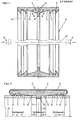
- Fig. 1 eine Schnittansicht einer Dichtmanschette gemäß der Erfindung und
- Fig. 2 eine Teil-Schnittansicht der in Fig. 1 gezeigten, mittels eines Schellenbandes kontraktierten Dichtmanschette in Verbindung mit den glattzylindrischen Enden zweier Rohre.
- Fig. 1 is a sectional view of a sealing sleeve according to the invention and
- Fig. 2 is a partial sectional view of the sealing sleeve shown in Fig. 1, contracted by means of a clamp band in connection with the smooth cylindrical ends of two tubes.
Mit 1 und 2 sind in Fig. 2 die glattzylindrischen Enden zweier abgedichtet zu verbindender Rohre mit gleichem Außen- und Innendurchmesser bezeichnet. Bei diesen Rohren 1, 2 kann es sich um Abwasserrohre aus Stahl oder Gußeisen handeln. Zur abgedichteten Verbindung dieser beiden Rohre 1, 2 dient die Vorrichtung 3, welche eine Dichtmanschette 4 aus elastomerem Material sowie ein Schellenband 5 aufweist, welches zum Verspannen der Dichtmanschette 4 dient.1 and 2 in FIG. 2 denote the smooth cylindrical ends of two pipes to be connected in a sealed manner, with the same outside and inside diameters. These
Das Schellenband 5 aus vorzugsweise dünnwandigem Edelstahlblech ist zu diesem Zweck mit zwei radial nach außen abstehenden Abkantungen versehen, welche mittels Schrauben in bekannter Weise gegeneinander gezogen werden können, um den Innendurchmesser des Schellenbandes zu verkleinern. Diese Teile des Schellenbandes 5 sind, da bekannt, nicht gezeigt.For this purpose, the
Die von dem Schellenband 5 umfaßte Dichtmanschette 4 weist an ihren innenliegenden beiden Außenrandbereichen jeweils zwei ringförmige Dichtlippen 6, 7 und einen mittig angeordneten, radial nach innen ragenden, ringförmigen Steg 8 auf, welcher als Anschlag für die beiden einzusteckenden Rohr-Stirnenden 9, 10 dient. Zwischen jeder Seite des Stegs 8 und jeder innersten Dichtlippe 7 erstreckt sich ein radial nach außen abgeschrägter Innenwandabschnitt 11. Der Neigungswinkel cK dieser Innenwandabschnitte 11 gegenüber der verlängerten Längsachse 12 der Vorrichtung 3 beträgt beim Ausführungsbeispiel 15° ± 1°.The sealing
Beim Einstecken der glattzylindrischen Rohrenden 1, 2 in die Vorrichtung 3 bzw. Dichtmanschette 4 werden die-Dichtlippen 6, 7 nach innen umgebogen und die schrägen Innenwandabschnitte 11 dienen als Führung für die Rohrenden, bis die Rohr-Stirnenden 9, 10 an dem ringförmigen Steg 8 anschlagen. Die Dichtmanschette 4 ist unter Berücksichtigung der schwankenden Außendurchmesser der Rohre 1, 2 so bemessen, daß die Rohr-Stirnenden 9, 10 entweder unmittelbar in den Ecken 14 (Fig. 1) oder etwas radial nach innen versetzt von diesen Ecken 14 zu liegen kommt. Es versteht sich, daß die Dichtmanschette 4 in dieser Montagephase sich im entspannten Zustand befindet. Zur Herstellung der abgedichteten Rohrverbindung wird das Schellenband 5 mittels der nicht gezeigten Schrauben in Umfangsrichtung zusammengezogen und dadurch die Dichtmanschette 4 radial nach innen vorgespannt. Dabei werden die Dichtlippen 6, 7 -gegen den Außenumfang der Rohre 1, 2 gepreßt, wodurch zwei erste Dichtbereiche (A) (Fig. 2) erzeugt werden. Aufgrund des flachen Neigungswinkels α der Innenwandabschnitte 11 wird zusätzlich eine ringförmige Zone 13 dieser Innenwandabschnitte 11 gegen den Außenumfang der Rohre 1, 2 neben deren Stirnenden 9, 10 gepreßt,-wodurch zwei zweite ringförmige Dichtbereiche B neben jeder Seite des mittigen Stegs 8 geschaffen werden. Die axiale Länge dieser Dichtbereiche B hängt auch von dem Grad der Vorspannung der Dichtmanschette 4 ab und kann daher in gewissen Grenzen eingestellt werden.When the smooth
Claims (3)
Priority Applications (1)
| Application Number | Priority Date | Filing Date | Title |
|---|---|---|---|
| AT85113106T ATE51695T1 (en) | 1984-11-03 | 1985-10-16 | DEVICE FOR THE SEALED CONNECTION OF TWO PIPES WITH SMOOTH CYLINDRICAL ENDS. |
Applications Claiming Priority (2)
| Application Number | Priority Date | Filing Date | Title |
|---|---|---|---|
| DE3440258 | 1984-11-03 | ||
| DE19843440258 DE3440258A1 (en) | 1984-11-03 | 1984-11-03 | DEVICE FOR THE SEALED CONNECTION OF TWO TUBES WITH SMOOTH CYLINDRICAL ENDS |
Publications (4)
| Publication Number | Publication Date |
|---|---|
| EP0180824A2 true EP0180824A2 (en) | 1986-05-14 |
| EP0180824A3 EP0180824A3 (en) | 1987-09-09 |
| EP0180824B1 EP0180824B1 (en) | 1990-04-04 |
| EP0180824B2 EP0180824B2 (en) | 1994-02-23 |
Family
ID=6249458
Family Applications (1)
| Application Number | Title | Priority Date | Filing Date |
|---|---|---|---|
| EP85113106A Expired - Lifetime EP0180824B2 (en) | 1984-11-03 | 1985-10-16 | Device for sealed connection of two pipes with smooth cylindrical ends |
Country Status (3)
| Country | Link |
|---|---|
| EP (1) | EP0180824B2 (en) |
| AT (1) | ATE51695T1 (en) |
| DE (2) | DE3440258A1 (en) |
Cited By (7)
| Publication number | Priority date | Publication date | Assignee | Title |
|---|---|---|---|---|
| DE4103702C1 (en) * | 1991-02-07 | 1992-06-04 | Mero Werke Kg | |
| US5351997A (en) * | 1990-07-27 | 1994-10-04 | Taylor Kerr (Couplings) Ltd. | Pipe coupling |
| GB2249366B (en) * | 1990-07-27 | 1994-12-14 | Taylor Kerr | Pipe coupling |
| EP0656502A2 (en) * | 1993-12-02 | 1995-06-07 | Peter Ilesic | Sealing device for sealing pipelines |
| US5639102A (en) * | 1993-12-02 | 1997-06-17 | Ile+E,Hac S+Ee I+E,Hac C+Ee ; Peter | Seal arrangement for sealing a conduit |
| US6457748B1 (en) | 1996-05-31 | 2002-10-01 | Taylor Kerr (Couplings) Ltd. | Fire-resistant pipe coupling |
| KR100562754B1 (en) * | 2005-11-29 | 2006-03-21 | 백충원 | A connecting device of plastics pipe |
Families Citing this family (3)
| Publication number | Priority date | Publication date | Assignee | Title |
|---|---|---|---|---|
| DE3710852C1 (en) * | 1987-04-01 | 1988-03-10 | Rasmussen Gmbh | Pipe coupling |
| AT390132B (en) * | 1988-03-10 | 1990-03-26 | Eternit Werke Hatschek L | Pipe coupling |
| DE3817714A1 (en) * | 1988-05-25 | 1989-12-07 | Dueker Eisenwerk | Device for the sealed connection of two cast-iron pipes |
Citations (4)
| Publication number | Priority date | Publication date | Assignee | Title |
|---|---|---|---|---|
| GB880847A (en) * | 1959-08-10 | 1961-10-25 | Stoneware Ltd | Coupling for pipes |
| DE2744739A1 (en) * | 1976-10-13 | 1978-04-20 | Hobas Eng Ag | PIPE COUPLING AND METHOD OF MANUFACTURING IT |
| DE8107112U1 (en) * | 1981-03-12 | 1982-01-14 | WOCO Franz-Josef Wolf & Co, 6483 Bad Soden-Salmünster | CONNECTOR |
| DE3404739C1 (en) * | 1984-02-10 | 1985-07-25 | Rasmussen Gmbh, 6457 Maintal | Plug-in coupling for connecting the ends of two pipes |
Family Cites Families (3)
| Publication number | Priority date | Publication date | Assignee | Title |
|---|---|---|---|---|
| DE7316306U (en) * | 1973-08-02 | Eternit Ag | Clamp for connecting sleeveless pipes | |
| CH432956A (en) * | 1965-11-10 | 1967-03-31 | Eternit Ag | Plug-in coupling for pipes |
| DE3122708C2 (en) * | 1981-06-06 | 1983-04-21 | Rasmussen Gmbh, 6457 Maintal | Rubber sleeve for a broadband clamp |
-
1984
- 1984-11-03 DE DE19843440258 patent/DE3440258A1/en active Granted
-
1985
- 1985-10-16 EP EP85113106A patent/EP0180824B2/en not_active Expired - Lifetime
- 1985-10-16 AT AT85113106T patent/ATE51695T1/en active
- 1985-10-16 DE DE8585113106T patent/DE3576992D1/en not_active Expired - Fee Related
Patent Citations (4)
| Publication number | Priority date | Publication date | Assignee | Title |
|---|---|---|---|---|
| GB880847A (en) * | 1959-08-10 | 1961-10-25 | Stoneware Ltd | Coupling for pipes |
| DE2744739A1 (en) * | 1976-10-13 | 1978-04-20 | Hobas Eng Ag | PIPE COUPLING AND METHOD OF MANUFACTURING IT |
| DE8107112U1 (en) * | 1981-03-12 | 1982-01-14 | WOCO Franz-Josef Wolf & Co, 6483 Bad Soden-Salmünster | CONNECTOR |
| DE3404739C1 (en) * | 1984-02-10 | 1985-07-25 | Rasmussen Gmbh, 6457 Maintal | Plug-in coupling for connecting the ends of two pipes |
Cited By (9)
| Publication number | Priority date | Publication date | Assignee | Title |
|---|---|---|---|---|
| US5351997A (en) * | 1990-07-27 | 1994-10-04 | Taylor Kerr (Couplings) Ltd. | Pipe coupling |
| GB2249366B (en) * | 1990-07-27 | 1994-12-14 | Taylor Kerr | Pipe coupling |
| DE4103702C1 (en) * | 1991-02-07 | 1992-06-04 | Mero Werke Kg | |
| EP0656502A2 (en) * | 1993-12-02 | 1995-06-07 | Peter Ilesic | Sealing device for sealing pipelines |
| EP0656502A3 (en) * | 1993-12-02 | 1996-01-10 | Peter Ilesic | Sealing device for sealing pipelines. |
| US5639102A (en) * | 1993-12-02 | 1997-06-17 | Ile+E,Hac S+Ee I+E,Hac C+Ee ; Peter | Seal arrangement for sealing a conduit |
| AU681449B2 (en) * | 1993-12-02 | 1997-08-28 | Peter Ilesic | Sealing arrangement for sealing conduits |
| US6457748B1 (en) | 1996-05-31 | 2002-10-01 | Taylor Kerr (Couplings) Ltd. | Fire-resistant pipe coupling |
| KR100562754B1 (en) * | 2005-11-29 | 2006-03-21 | 백충원 | A connecting device of plastics pipe |
Also Published As
| Publication number | Publication date |
|---|---|
| EP0180824A3 (en) | 1987-09-09 |
| EP0180824B1 (en) | 1990-04-04 |
| DE3576992D1 (en) | 1990-05-10 |
| DE3440258C2 (en) | 1987-04-30 |
| ATE51695T1 (en) | 1990-04-15 |
| EP0180824B2 (en) | 1994-02-23 |
| DE3440258A1 (en) | 1986-05-22 |
Similar Documents
| Publication | Publication Date | Title |
|---|---|---|
| DE60214479T2 (en) | Reusable coupling for connecting reinforced hose ends | |
| EP0477704B1 (en) | Contracted pipecoupling | |
| DE3330443A1 (en) | PIPE COUPLING | |
| DE3403954A1 (en) | LOW-MANIPULATOR | |
| EP0111271B1 (en) | Pipe of plastic, especially for sewage | |
| EP0180824B1 (en) | Device for sealed connection of two pipes with smooth cylindrical ends | |
| EP0521822A1 (en) | Device for the connection of two jacket tubes | |
| DE2621044A1 (en) | PIPE CONNECTION | |
| EP0557594B1 (en) | Method for mounting a connection element | |
| CH461199A (en) | Pipe coupling | |
| DE3247452C1 (en) | Pipe connection | |
| EP0616162A1 (en) | Flanged ring, attachable to a thin-walled pipe and its method of manufacture | |
| DE2922403A1 (en) | PIPE CONNECTION | |
| EP0575727A1 (en) | Pipe joint | |
| EP1306601B1 (en) | Compression fitting for the connection of at least one pipe | |
| AT393309B (en) | DEVICE FOR CONNECTING FLANGED TUBES | |
| DE4103702C1 (en) | ||
| EP0498322B1 (en) | Device for the sealed connection of the smoothed cylindrical ends of two pipes | |
| CH674764A5 (en) | Seal for abutting pipes, fittings or housings - has sealing ring between abutting parts, with support bead and radially inward pointing sealing lip | |
| DE3911258C2 (en) | ||
| EP0985867A1 (en) | Plastics corrugated tube and the combination of this tube with a sleeve | |
| DE2815249A1 (en) | METHOD AND DEVICE FOR SEALING A PIPE JOINT | |
| DE3007509A1 (en) | DEVICE FOR CONNECTING TWO TUBES | |
| DE4126708A1 (en) | Plastics or plastics coated pipe coupling - has cage forming groove to hold even rigid inflexible sealing rings | |
| DE2657663B2 (en) | Securing the mechanical connection and sealing of the ends of cylindrical pipes in sleeves made of plastic |
Legal Events
| Date | Code | Title | Description |
|---|---|---|---|
| PUAI | Public reference made under article 153(3) epc to a published international application that has entered the european phase |
Free format text: ORIGINAL CODE: 0009012 |
|
| AK | Designated contracting states |
Kind code of ref document: A2 Designated state(s): AT BE CH DE FR GB IT LI NL SE |
|
| PUAL | Search report despatched |
Free format text: ORIGINAL CODE: 0009013 |
|
| AK | Designated contracting states |
Kind code of ref document: A3 Designated state(s): AT BE CH DE FR GB IT LI NL SE |
|
| 17P | Request for examination filed |
Effective date: 19871028 |
|
| 17Q | First examination report despatched |
Effective date: 19880928 |
|
| GRAA | (expected) grant |
Free format text: ORIGINAL CODE: 0009210 |
|
| AK | Designated contracting states |
Kind code of ref document: B1 Designated state(s): AT BE CH DE FR GB IT LI NL SE |
|
| REF | Corresponds to: |
Ref document number: 51695 Country of ref document: AT Date of ref document: 19900415 Kind code of ref document: T |
|
| REF | Corresponds to: |
Ref document number: 3576992 Country of ref document: DE Date of ref document: 19900510 |
|
| GBT | Gb: translation of ep patent filed (gb section 77(6)(a)/1977) | ||
| ET | Fr: translation filed | ||
| ITF | It: translation for a ep patent filed |
Owner name: STUDIO JAUMANN |
|
| PLBI | Opposition filed |
Free format text: ORIGINAL CODE: 0009260 |
|
| 26 | Opposition filed |
Opponent name: RASMUSSEN GMBH Effective date: 19901221 |
|
| NLR1 | Nl: opposition has been filed with the epo |
Opponent name: RASMUSSEN GMBH |
|
| PG25 | Lapsed in a contracting state [announced via postgrant information from national office to epo] |
Ref country code: DE Effective date: 19910702 |
|
| ITTA | It: last paid annual fee | ||
| PUAH | Patent maintained in amended form |
Free format text: ORIGINAL CODE: 0009272 |
|
| STAA | Information on the status of an ep patent application or granted ep patent |
Free format text: STATUS: PATENT MAINTAINED AS AMENDED |
|
| RAP2 | Party data changed (patent owner data changed or rights of a patent transferred) |
Owner name: MERO-WERKE DR.-ING. MAX MENGERINGHAUSEN GMBH & CO. |
|
| 27A | Patent maintained in amended form |
Effective date: 19940223 |
|
| AK | Designated contracting states |
Kind code of ref document: B2 Designated state(s): AT BE CH DE FR GB IT LI NL SE |
|
| REG | Reference to a national code |
Ref country code: CH Ref legal event code: AEN |
|
| NLT2 | Nl: modifications (of names), taken from the european patent patent bulletin |
Owner name: MERO-WERKE DR.-ING. MAX MENGERINGHAUSEN GMBH & CO. |
|
| NLR2 | Nl: decision of opposition | ||
| ITF | It: translation for a ep patent filed |
Owner name: STUDIO JAUMANN |
|
| NLR3 | Nl: receipt of modified translations in the netherlands language after an opposition procedure | ||
| GBTA | Gb: translation of amended ep patent filed (gb section 77(6)(b)/1977) |
Effective date: 19940511 |
|
| ET3 | Fr: translation filed ** decision concerning opposition | ||
| PGFP | Annual fee paid to national office [announced via postgrant information from national office to epo] |
Ref country code: AT Payment date: 19941006 Year of fee payment: 10 |
|
| PGFP | Annual fee paid to national office [announced via postgrant information from national office to epo] |
Ref country code: GB Payment date: 19941011 Year of fee payment: 10 |
|
| EAL | Se: european patent in force in sweden |
Ref document number: 85113106.0 |
|
| PGFP | Annual fee paid to national office [announced via postgrant information from national office to epo] |
Ref country code: BE Payment date: 19950807 Year of fee payment: 11 |
|
| PGFP | Annual fee paid to national office [announced via postgrant information from national office to epo] |
Ref country code: CH Payment date: 19950922 Year of fee payment: 11 |
|
| PGFP | Annual fee paid to national office [announced via postgrant information from national office to epo] |
Ref country code: FR Payment date: 19950928 Year of fee payment: 11 |
|
| PG25 | Lapsed in a contracting state [announced via postgrant information from national office to epo] |
Ref country code: GB Effective date: 19951016 Ref country code: AT Effective date: 19951016 |
|
| PGFP | Annual fee paid to national office [announced via postgrant information from national office to epo] |
Ref country code: SE Payment date: 19951017 Year of fee payment: 11 |
|
| PGFP | Annual fee paid to national office [announced via postgrant information from national office to epo] |
Ref country code: NL Payment date: 19951027 Year of fee payment: 11 |
|
| GBPC | Gb: european patent ceased through non-payment of renewal fee |
Effective date: 19951016 |
|
| PG25 | Lapsed in a contracting state [announced via postgrant information from national office to epo] |
Ref country code: SE Effective date: 19961017 |
|
| PG25 | Lapsed in a contracting state [announced via postgrant information from national office to epo] |
Ref country code: LI Effective date: 19961031 Ref country code: CH Effective date: 19961031 Ref country code: BE Effective date: 19961031 |
|
| BERE | Be: lapsed |
Owner name: MERO-WERKE DR.-ING. MAX MENGERINGHAUSEN G.M.B.H. Effective date: 19961031 |
|
| PG25 | Lapsed in a contracting state [announced via postgrant information from national office to epo] |
Ref country code: NL Effective date: 19970501 |
|
| REG | Reference to a national code |
Ref country code: CH Ref legal event code: PL |
|
| PG25 | Lapsed in a contracting state [announced via postgrant information from national office to epo] |
Ref country code: FR Effective date: 19970630 |
|
| NLV4 | Nl: lapsed or anulled due to non-payment of the annual fee |
Effective date: 19970501 |
|
| EUG | Se: european patent has lapsed |
Ref document number: 85113106.0 |
|
| REG | Reference to a national code |
Ref country code: FR Ref legal event code: ST |
|
| APAH | Appeal reference modified |
Free format text: ORIGINAL CODE: EPIDOSCREFNO |