EP0575727A1 - Pipe joint - Google Patents
Pipe joint Download PDFInfo
- Publication number
- EP0575727A1 EP0575727A1 EP93106710A EP93106710A EP0575727A1 EP 0575727 A1 EP0575727 A1 EP 0575727A1 EP 93106710 A EP93106710 A EP 93106710A EP 93106710 A EP93106710 A EP 93106710A EP 0575727 A1 EP0575727 A1 EP 0575727A1
- Authority
- EP
- European Patent Office
- Prior art keywords
- sleeve
- pipe
- tube
- pipe joint
- annular
- Prior art date
- Legal status (The legal status is an assumption and is not a legal conclusion. Google has not performed a legal analysis and makes no representation as to the accuracy of the status listed.)
- Granted
Links
Images
Classifications
-
- F—MECHANICAL ENGINEERING; LIGHTING; HEATING; WEAPONS; BLASTING
- F01—MACHINES OR ENGINES IN GENERAL; ENGINE PLANTS IN GENERAL; STEAM ENGINES
- F01N—GAS-FLOW SILENCERS OR EXHAUST APPARATUS FOR MACHINES OR ENGINES IN GENERAL; GAS-FLOW SILENCERS OR EXHAUST APPARATUS FOR INTERNAL COMBUSTION ENGINES
- F01N13/00—Exhaust or silencing apparatus characterised by constructional features ; Exhaust or silencing apparatus, or parts thereof, having pertinent characteristics not provided for in, or of interest apart from, groups F01N1/00 - F01N5/00, F01N9/00, F01N11/00
- F01N13/18—Construction facilitating manufacture, assembly, or disassembly
- F01N13/1805—Fixing exhaust manifolds, exhaust pipes or pipe sections to each other, to engine or to vehicle body
- F01N13/1811—Fixing exhaust manifolds, exhaust pipes or pipe sections to each other, to engine or to vehicle body with means permitting relative movement, e.g. compensation of thermal expansion or vibration
-
- F—MECHANICAL ENGINEERING; LIGHTING; HEATING; WEAPONS; BLASTING
- F16—ENGINEERING ELEMENTS AND UNITS; GENERAL MEASURES FOR PRODUCING AND MAINTAINING EFFECTIVE FUNCTIONING OF MACHINES OR INSTALLATIONS; THERMAL INSULATION IN GENERAL
- F16L—PIPES; JOINTS OR FITTINGS FOR PIPES; SUPPORTS FOR PIPES, CABLES OR PROTECTIVE TUBING; MEANS FOR THERMAL INSULATION IN GENERAL
- F16L27/00—Adjustable joints, Joints allowing movement
- F16L27/10—Adjustable joints, Joints allowing movement comprising a flexible connection only, e.g. for damping vibrations
- F16L27/1021—Adjustable joints, Joints allowing movement comprising a flexible connection only, e.g. for damping vibrations comprising an intermediate resilient element, e.g. a ring
Definitions
- the invention is based on a pipe joint according to the preamble of claim 1.
- a pipe joint is known from European patent specification 0 208 128 B1, in which the sleeve forms a part with a pipe extension.
- the cuff which is initially open at the free end, is pushed over the wire press rings on both sides of the joint tube and closed by flanging (Fig.3a).
- FIG. 3b Another version of a pipe joint manufactured and sold by the applicant provides a sleeve which is divided in the middle transversely to the longitudinal axis. After the wire press rings have been pulled onto the articulated tube, one half sleeve is pushed onto this from one side and the other half sleeve with tube attachment is pushed as far as it will go and welded to each other (Fig. 3b).
- the cross-section of the chamber holding the wire compression rings in these two designs, given by the respective sleeve, does not take into account dimensional variations due to tolerances, for example the unfolding of the articulated tube, the wire compression rings and the sleeve itself.
- the object of the invention is therefore to provide a tubular joint in which tolerances of the type mentioned above no longer have any influence on the prestressing of the wire compression rings.
- FIGS. 1, 2, 3a and 3b serve in a known manner to dampen axial and / or lateral vibrations A and L, so that their task and function will not be discussed in detail.
- Each drawing shows pipe parts 2, e.g. a motor vehicle exhaust system, in which a pipe joint 1 is inserted. All representations are based on a pipe joint shown in FIG. 3a, as is known from European Patent 0 208 128 B1. The parts that are the same in function and design are identified in the drawings by the same item numbers.
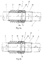
- FIG. 3a and 3b show the known designs already mentioned in a simplified representation in longitudinal section.
- the pipe joint according to FIG. 3a has an articulated pipe 3, which is attached gas-tight at one end in a pipe part 2.
- the articulated tube 3 has an annular fold-out 4. This serves in the axial direction as an abutment for two wire press rings 5.
- a sleeve tube 27 consisting of an annular sleeve 28 and tube extension 29 has a flanged edge 28a at the free end. After the sleeve 28 is pushed over the wire press rings 5, the flanged edge 28a is bent towards the center, so that the press rings 5 are located in an annular chamber closed on both sides.
- a sealing bellows 12 is attached in a gas-tight manner, for example welded, between the flanged edge 28a of the sleeve 28 and the one pipe part 2.
- FIG. 3b differs from FIG. 3a in the design of the cuff.
- the cuff closed on both sides is divided in the middle transversely to the longitudinal axis of the pipe joint 1.
- One half-sleeve 36 is attached to the sealing bellows 12, while the other half-sleeve 38 forms a sleeve tube 37 with a tube extension 39.
- the sleeve tube 37 is pushed onto the stop and the two half sleeves 36 and 38 are welded to one another (item 40).
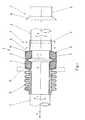
- FIG. 1 shows in a simplified representation a first embodiment of a pipe joint 1 in longitudinal section according to the invention.
- This version differs from the pipe joints described above by the design of the sleeve and the sleeve pipe.
- An annular sleeve 6 is provided which is closed on the connection side of the sealing bellows 12.
- the sleeve 6 protrudes on the other side in the axial direction slightly above the wire press ring 5.
- the cuff 6 is closed by a flange tube 7, which consists of a tube extension 9 with an annular flange 8.
- the outside diameter of the ring flange 8 is the same as the inside diameter of the sleeve 6, as can be seen from the offset dashed line of the flange tube 7.
- an annular abutment 10 is inserted into the trough of the bellows 12 adjoining the sleeve 6 which is indicated by dashed lines.
- the flange tube 7 is pressed into the sleeve 6 in the direction of the arrow.
- the sleeve 6 is then connected to the ring flange 8 of the flange tube 7 in a form-fitting and gas-tight manner, for example by a weld seam 11.
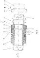
- FIG. 2 shows a simplified representation of a second embodiment of a pipe joint 1 in longitudinal section according to the invention.
- This embodiment corresponds to FIG. 1 in that a sleeve 16 is provided which is closed on the connection side of the sealing bellows 12. The other open side of the sleeve, however, stands back somewhat in the axial direction with respect to the outer wire press ring 5.
- the cuff 16 is closed by a stepped tube 17, which consists of a tubular extension 19 with an annular flange 18 and a transition 20.
- the inside diameter of the transition 20 is the same as the outside diameter of the sleeve 6, as can be seen from the stepped line 17 of the stepped tube 17.
- the sleeve 16 stands back from the outer wire press ring 5 to such an extent that the stepped tube 17, which in this case crosses the sleeve 16, does not come into contact with the end face of the sleeve with its ring flange 18.
- the annular abutment 10 is used, as described for FIG. 1, and the stepped tube 17 is pressed with a force P corresponding to the required prestress in the direction of the arrow against the outer wire press ring 5. While maintaining the pressure, the sleeve 16 is then connected to the transition 20 of the stepped tube 17 in a form-fitting and gas-tight manner, e.g. through a weld seam 21.
Abstract
Description
Die Erfindung geht von einem Rohrgelenk gemäß dem Oberbegriff des Anspruchs 1 aus.The invention is based on a pipe joint according to the preamble of
Durch die Europäische Patentschrift 0 208 128 B1 istein Rohrgelenk bekannt, bei der die Manschette mit einem Rohransatz ein Teil bildet. Die zunächst am freien Ende offene Manschette wird über die an der Auffaltung des Gelenkrohres beiderseits anliegenden Drahtpreßringe geschoben und durch Umbördeln geschlossen (Fig.3a).A pipe joint is known from European patent specification 0 208 128 B1, in which the sleeve forms a part with a pipe extension. The cuff, which is initially open at the free end, is pushed over the wire press rings on both sides of the joint tube and closed by flanging (Fig.3a).
Eine weitere, von der Anmelderin hergestellte und vertriebene Ausführung eines Rohrgelenkes sieht eine quer zur Längsachse in der Mitte geteilte Manschette vor. Nach dem Aufziehen der Drahtpreßringe auf das Gelenkrohr wird auf dieses von der einen Seite die eine Halbmanschette und von der anderen Seite die andere Halbmanschette mit Rohransatz bis zum Anschlag aufgeschoben und miteinander verschweißt (Fig.3b).Another version of a pipe joint manufactured and sold by the applicant provides a sleeve which is divided in the middle transversely to the longitudinal axis. After the wire press rings have been pulled onto the articulated tube, one half sleeve is pushed onto this from one side and the other half sleeve with tube attachment is pushed as far as it will go and welded to each other (Fig. 3b).
Der bei diesen beiden Ausführungen durch die jeweilige Manschette vorgegebene Querschnitt der die Drahtpreßringe aufnehmenden Kammer läßt toleranzbedingte Maßabweichungen, z.B. der Auffaltung des Gelenkrohres, der Drahtpreßringe und der Manschette selber außer acht.The cross-section of the chamber holding the wire compression rings in these two designs, given by the respective sleeve, does not take into account dimensional variations due to tolerances, for example the unfolding of the articulated tube, the wire compression rings and the sleeve itself.
Der gewünschte Dämpfungsgrad wird jedoch nur erreicht, wenn die Drahtpreßringe unter einer bestimmten Vorspannung stehen. Diese ist mit den vorbeschriebenen Ausführungen nicht gewährleistet.The desired degree of damping, however, is only achieved if the wire compression rings are under a certain preload. This is not guaranteed with the above-described designs.
Die Aufgabe der Erfindung besteht daher darin, ein Rohrgelenk zu schaffen, bei dem Toleranzen der vorstehend genannten Art keinen Einfluß auf die Vorspannung der Drahtpreßringe mehr haben.The object of the invention is therefore to provide a tubular joint in which tolerances of the type mentioned above no longer have any influence on the prestressing of the wire compression rings.
Diese Aufgabe wird durch die im Anspruch 1 angegebenen Merkmale gelöst. Die Unteransprüche zeigen vorteilhafte Ausgestaltungen des Erfindungsgegenstandes auf.This object is achieved by the features specified in
Die durch die Erfindung erzielten Vorteile bestehen insbesondere darin, daß durch die in axialer Richtung übereinanderschiebbaren Teile des Manschettenrohres Toleranzen ausgeglichen werden und eine definierte Vorspannung der Drahtpreßringe eingestellt werden kann, bevor die beiden Teile formschlüssig verbunden werden.The advantages achieved by the invention consist in particular in that tolerances are compensated for by the parts of the sleeve tube which can be pushed one over the other in the axial direction and a defined prestressing of the wire press rings can be set before the two parts are connected in a positive manner.
Anhand von zwei Ausführungsbeispielen wird die Erfindung in Verbindung mit den Zeichnungen nachfolgend näher erläutert. Es zeigt:
- Fig.1
- in vereinfachter Darstellung ein erstes Ausführungsbeispiel der Erfindung im Längsschnitt.
- Fig.2
- in vereinfachter Darstellung ein zweites Ausführungsbeispiel der Erfindung im Längsschnitt.
- Fig.3a und 3b
- in vereinfachter Darstellung zwei bekannte Ausführungen eines Rohrgelenks im Längsschnitt.
- Fig. 1
- in a simplified representation, a first embodiment of the invention in longitudinal section.
- Fig. 2
- in a simplified representation, a second embodiment of the invention in longitudinal section.
- 3a and 3b
- in a simplified representation two known versions of a pipe joint in longitudinal section.
Die in den Figuren 1, 2, 3a und 3b gezeigten Ausführungen dienen in bekannter Weise zur Dämpfung von axialen und/oder lateralen Schwingungen A bzw. L, so daß auf ihre Aufgabe und Funktion nicht näher eingegangen wird. Jede Zeichnung zeigt Rohrleitungsteile 2, z.B. einer Kraftfahrzeug-Abgasanlage, in die ein Rohrgelenk 1 eingefügt ist. Alle Darstellungen basieren auf einem in Fig.3a dargestellten Rohrgelenk, wie es durch die Europäische Patentschrift 0 208 128 B1 bekannt ist. Die in Funktion und Ausbildung gleichen Teile sind in den Zeichnungen durch gleiche Positionszahlen gekennzeichnet.The designs shown in FIGS. 1, 2, 3a and 3b serve in a known manner to dampen axial and / or lateral vibrations A and L, so that their task and function will not be discussed in detail. Each drawing shows
Die Fig. 3a und die Fig.3b zeigen die eingangs bereits erwähnten bekannten Ausführungen in vereinfachter Darstellung im Längsschnitt.
Das Rohrgelenk gemäß Fig.3a hat ein Gelenkrohr 3, das mit seinem einen Ende in einem Rohrleitungsteil 2 gasdicht befestigt ist. Zum andere Ende hin hat das Gelenkrohr 3 eine ringförmige Auffaltung 4. Diese dient in axialer Richtung als Widerlager für zwei Drahtpreßringe 5. Ein aus einer ringförmigen Manschette 28 und Rohransatz 29 bestehendes Manschettenrohr 27 hat am freien Ende einen Bördelrand 28a. Nachdem die Manschette 28 über die Drahtpreßringe 5 geschoben ist, wird der Bördelrand 28a zur Mitte hin umgebogen, so daß sich die Preßringe 5 in einer beidseitig geschlossenen ringförmigen Kammer befinden. Zwischen dem Gelenkrohr 3 und der Manschette 28 besteht ein radialer Zwischenraum, um den notwendigen gegenseitigen Bewegungsspielraum zu gewährleisten. Die Drahtpreßringe 5 sind nicht gasdicht. Es besteht daher die Gefahr, daß Teile der durch das Rohrgelenk 1 geleiteten Abgase oder dergleichen nach außen dringen. Um dieses zu verhindern, ist zwischen dem Bördelrand 28a der Manschette 28 und dem einen Rohrleitungsteil 2 ein Dichtungsbalg 12 gasdicht befestigt, z.B. angeschweißt.3a and 3b show the known designs already mentioned in a simplified representation in longitudinal section.
The pipe joint according to FIG. 3a has an articulated
Die Fig.3b unterscheidet sich gegenüber der Fig.3a in der Ausbildung der Manschette. Die beidseits beschlossene Manschette ist quer zur Längsachse des Rohrgelenkes 1 in der Mitte geteilt. Die eine Halbmanschette 36 ist am Dichtungsbalg 12 befestigt, während die andere Halbmanschette 38 mit einem Rohransatz 39 ein Manschettenrohr 37 bildet. Nachdem das Gelenkrohr 3 mit den aufgezogenen Drahtpreßringen 5 in die Rohrhälfte 12/36 eingesetzt ist, wird das Manschettenrohr 37 auf Anschlag aufgeschoben und die beiden Halbmanschetten 36 und 38 miteinander verschweißt (Pos.40).3b differs from FIG. 3a in the design of the cuff. The cuff closed on both sides is divided in the middle transversely to the longitudinal axis of the
Bei diesen beiden Ausführungen bestimmt die Summe der einflußnehmenden Toleranzen in unzulässigen Umfang die Vorspannung der Drahtpreßringe 5. Mit den Ausführungen gemäß Fig.1 und Fig.2 ist eine genaue Bemessung der Vorspannung möglich.In the case of these two designs, the sum of the influencing tolerances determines the prestressing of the
Fig.1 zeigt in vereinfachter Darstellung ein erstes Ausführungsbeispiel eines Rohrgelenkes 1 im Längsschnitt gemäß der Erfindung. Diese Ausführung unterscheidet sich von den vorbeschriebenen Rohrgelenken durch die Ausbildung der Manschette und des Manschettenrohres. Es ist eine ringförmige Manschette 6 vorgesehen, die auf der Anschlußseite des Dichtungsbalges 12 geschlossen ist. Die Manschette 6 steht auf der anderen Seite in axialer Richtung etwas über den Drahtpreßring 5 vor. Die Manschette 6 wird durch ein Flanschrohr 7 geschlossen, das aus einen Rohransatz 9 mit einem Ringflansch 8 besteht. Der Außendurchmesser des Ringflansches 8 ist im Paßnaß gleich dem Innendurchmesser der Manschette 6, wie die abgesetzte strichlinierte Darstellung des Flanschrohres 7 gut erkennen läßt.1 shows in a simplified representation a first embodiment of a
Zum Einstellen einer definierten Vorspannung der Drahtpreßringe 5 wird in das an die Manschette 6 anschließende Wellental des Balges 12 ein ringförmiges Widerlager 10 eingesetzt, das andeutungsweise strichliniert dargestellt ist. Mit einer, der erforderlichen Vorspannung entsprechenden Kraft P wird das Flanschrohr 7 in Pfeilrichtung in die Manschette 6 gedrückt. Unter Beibehalten des Andrucks wird sodann die Manschette 6 mit dem Ringflansch 8 des Flanschrohres 7 formschlüssig und gasdicht verbunden, z.B. durch eine Schweißnaht 11.In order to set a defined pre-tension of the
Fig.2 zeigt in vereinfachter Darstellung ein zweites Ausführungsbeispiel eines Rohrgelenkes 1 im Längsschnitt gemäß der Erfindung. Diese Ausführung stimmt mit der Fig.1 darin überein, daß eine Manschette 16 vorgesehen ist, die auf der Anschlußseite des Dichtungsbalges 12 geschlossen ist. Die andere offene Seite der Manschette steht jedoch in axialer Richtung gegenüber dem außen liegenden Drahtpreßring 5 etwas zurücksteht. Die Manschette 16 wird durch ein Stufenrohr 17 geschlossen, das aus einem Rohransatz 19 mit Ringflansch 18 und Übertritt 20 besteht. Der Innendurchmesser des Übertritts 20 ist im Paßmaß gleich dem Außendurchmesser der Manschette 6, wie die abgesetzte strichlinierte Darstellung des Stufenrohres 17 gut erkennen läßt. Die Manschette 16 steht gegenüber dem außenliegenden Drahtpreßring 5 soweit zurück, daß das in diesem Fall über die Manschette 16 greifende Stufenrohr 17 mit seinen Ringflansch 18 nicht in Anlage an die Stirnseite der Manschette gelangt.2 shows a simplified representation of a second embodiment of a
Zur Einstellung einer definierten Vorspannung der Drahtpreßringe 5 wird, wie zu Fig.1 beschrieben, das ringförmige Widerlager 10 eingesetzt und das Stufenrohr 17 mit einer der erforderlichen Vorspannung entsprechenden Kraft P in Pfeilrichtung gegen den außenliegenden Drahtpreßring 5 gedrückt. Unter Beibehaltung des Andrucks wird sodann die Manschette 16 mit dem Übertritt 20 des Stufenrohres 17 formschlüssig und gasdicht verbunden, z.B. durch eine Schweißnaht 21.To set a defined prestressing of the wire press rings 5, the
Claims (3)
dadurch gekennzeichnet,
daß die beiden Teile (6,7;16,17) des Manschettenrohres in axialer Richtung übereinandergreifen und formschlüssig miteinander verbunden sind.Pipe joint for the axial and lateral vibration decoupling of pipeline parts, which has an articulated pipe with an annular fold-out, two wire press rings resting on the fold-out and a sleeve pipe which encompasses the wire press rings from the outside in a form-fitting manner and which consists of two parts touching in the sleeve area,
characterized by
that the two parts (6,7; 16,17) of the sleeve tube overlap in the axial direction and are positively connected to one another.
Applications Claiming Priority (2)
| Application Number | Priority Date | Filing Date | Title |
|---|---|---|---|
| DE4220789A DE4220789A1 (en) | 1992-06-25 | 1992-06-25 | Pipe joint |
| DE4220789 | 1992-06-25 |
Publications (2)
| Publication Number | Publication Date |
|---|---|
| EP0575727A1 true EP0575727A1 (en) | 1993-12-29 |
| EP0575727B1 EP0575727B1 (en) | 1997-07-09 |
Family
ID=6461772
Family Applications (1)
| Application Number | Title | Priority Date | Filing Date |
|---|---|---|---|
| EP93106710A Expired - Lifetime EP0575727B1 (en) | 1992-06-25 | 1993-04-26 | Method of manufacturing a pipe joint |
Country Status (2)
| Country | Link |
|---|---|
| EP (1) | EP0575727B1 (en) |
| DE (2) | DE4220789A1 (en) |
Cited By (13)
| Publication number | Priority date | Publication date | Assignee | Title |
|---|---|---|---|---|
| GB2277969A (en) * | 1993-04-09 | 1994-11-16 | Iwk Regler Kompensatoren | Articulated coupling for internal combustion engine |
| EP0681097A1 (en) * | 1994-05-06 | 1995-11-08 | Witzenmann GmbH Metallschlauch-Fabrik Pforzheim | Flexible connecting element for tubular parts |
| US5639127A (en) * | 1995-12-08 | 1997-06-17 | Senior Engineering Investments Ag | Flexible coupler apparatus |
| WO1999036685A1 (en) * | 1998-01-20 | 1999-07-22 | Sjm Co., Ltd. | Exhaust decoupler system |
| US5957504A (en) * | 1997-04-10 | 1999-09-28 | Senior Engineering Investments Ag | Exhaust manifold attachment apparatus |
| US5971439A (en) * | 1997-01-17 | 1999-10-26 | Senior Engineering Investments Ag | Flexible coupler apparatus |
| US5984372A (en) * | 1997-04-10 | 1999-11-16 | Senior Engineering Investments Ag | Integrated flange-mesh ring assembly for decoupler apparatus |
| WO1999058891A1 (en) * | 1998-05-11 | 1999-11-18 | Lee Karl O | Vibration decoupling connector for exhaust systems |
| US5992896A (en) * | 1995-12-08 | 1999-11-30 | Senior Engineering Investments Ag | Flexible coupler apparatus |
| US6354632B1 (en) | 1999-05-24 | 2002-03-12 | Sjm Company Ltd. | Exhaust decoupler system |
| US6464257B1 (en) | 1997-04-10 | 2002-10-15 | Senior Investments Ag | Vibration decoupler apparatus |
| CN103867279A (en) * | 2012-12-11 | 2014-06-18 | 曼柴油机和涡轮机欧洲股份公司 | Compensator of exhaust gas aftertreatment system |
| US9506403B2 (en) | 2014-01-17 | 2016-11-29 | Rolls-Roycs Plc | Fastener |
Families Citing this family (1)
| Publication number | Priority date | Publication date | Assignee | Title |
|---|---|---|---|---|
| DE202007003592U1 (en) * | 2007-03-09 | 2008-07-24 | Witzenmann Gmbh | Flexible conduit element |
Citations (3)
| Publication number | Priority date | Publication date | Assignee | Title |
|---|---|---|---|---|
| GB2125502A (en) * | 1982-08-10 | 1984-03-07 | Iwk Regler Kompensatoren | Pipe coupling |
| EP0250901A2 (en) * | 1986-07-04 | 1988-01-07 | IWK Regler und Kompensatoren GmbH | Device for decoupling torsion movements between pipe parts |
| DE9208484U1 (en) * | 1992-06-25 | 1992-08-13 | Witzenmann Gmbh, Metallschlauch-Fabrik Pforzheim, 7530 Pforzheim, De |
Family Cites Families (1)
| Publication number | Priority date | Publication date | Assignee | Title |
|---|---|---|---|---|
| DE3610684A1 (en) * | 1986-03-29 | 1987-01-02 | Witzenmann Metallschlauchfab | JOINT CONNECTION OF PIPE PARTS, IN PARTICULAR FOR EXHAUST PIPES FROM MOTOR VEHICLES |
-
1992
- 1992-06-25 DE DE4220789A patent/DE4220789A1/en not_active Ceased
-
1993
- 1993-04-26 EP EP93106710A patent/EP0575727B1/en not_active Expired - Lifetime
- 1993-04-26 DE DE59306861T patent/DE59306861D1/en not_active Expired - Fee Related
Patent Citations (3)
| Publication number | Priority date | Publication date | Assignee | Title |
|---|---|---|---|---|
| GB2125502A (en) * | 1982-08-10 | 1984-03-07 | Iwk Regler Kompensatoren | Pipe coupling |
| EP0250901A2 (en) * | 1986-07-04 | 1988-01-07 | IWK Regler und Kompensatoren GmbH | Device for decoupling torsion movements between pipe parts |
| DE9208484U1 (en) * | 1992-06-25 | 1992-08-13 | Witzenmann Gmbh, Metallschlauch-Fabrik Pforzheim, 7530 Pforzheim, De |
Cited By (18)
| Publication number | Priority date | Publication date | Assignee | Title |
|---|---|---|---|---|
| GB2277969B (en) * | 1993-04-09 | 1996-01-24 | Iwk Regler Kompensatoren | Exhaust gas pipe particularly for motor vehicles |
| GB2277969A (en) * | 1993-04-09 | 1994-11-16 | Iwk Regler Kompensatoren | Articulated coupling for internal combustion engine |
| EP0681097A1 (en) * | 1994-05-06 | 1995-11-08 | Witzenmann GmbH Metallschlauch-Fabrik Pforzheim | Flexible connecting element for tubular parts |
| US5639127A (en) * | 1995-12-08 | 1997-06-17 | Senior Engineering Investments Ag | Flexible coupler apparatus |
| US5992896A (en) * | 1995-12-08 | 1999-11-30 | Senior Engineering Investments Ag | Flexible coupler apparatus |
| US5971439A (en) * | 1997-01-17 | 1999-10-26 | Senior Engineering Investments Ag | Flexible coupler apparatus |
| US6167622B1 (en) | 1997-04-10 | 2001-01-02 | Senior Investments Ag | Exhaust manifold attachment apparatus and method for fabricating same |
| US5984372A (en) * | 1997-04-10 | 1999-11-16 | Senior Engineering Investments Ag | Integrated flange-mesh ring assembly for decoupler apparatus |
| US5957504A (en) * | 1997-04-10 | 1999-09-28 | Senior Engineering Investments Ag | Exhaust manifold attachment apparatus |
| US6086110A (en) * | 1997-04-10 | 2000-07-11 | Senior Engineering Investments Ag | Vibration decoupling connector for exhaust systems |
| US6464257B1 (en) | 1997-04-10 | 2002-10-15 | Senior Investments Ag | Vibration decoupler apparatus |
| US5967565A (en) * | 1998-01-20 | 1999-10-19 | Sjm Co., Ltd. | Exhaust coupler system |
| WO1999036685A1 (en) * | 1998-01-20 | 1999-07-22 | Sjm Co., Ltd. | Exhaust decoupler system |
| WO1999058891A1 (en) * | 1998-05-11 | 1999-11-18 | Lee Karl O | Vibration decoupling connector for exhaust systems |
| US6354632B1 (en) | 1999-05-24 | 2002-03-12 | Sjm Company Ltd. | Exhaust decoupler system |
| CN103867279A (en) * | 2012-12-11 | 2014-06-18 | 曼柴油机和涡轮机欧洲股份公司 | Compensator of exhaust gas aftertreatment system |
| CN103867279B (en) * | 2012-12-11 | 2018-09-18 | 曼柴油机和涡轮机欧洲股份公司 | The compensator of exhaust after treatment system |
| US9506403B2 (en) | 2014-01-17 | 2016-11-29 | Rolls-Roycs Plc | Fastener |
Also Published As
| Publication number | Publication date |
|---|---|
| DE4220789A1 (en) | 1994-01-05 |
| DE59306861D1 (en) | 1997-08-14 |
| EP0575727B1 (en) | 1997-07-09 |
Similar Documents
| Publication | Publication Date | Title |
|---|---|---|
| EP0728979B1 (en) | Sealing connection between a plastic pipe and a connecting piece made of metal | |
| EP0580963B1 (en) | Articulated pipe | |
| EP0477704B1 (en) | Contracted pipecoupling | |
| EP0575727A1 (en) | Pipe joint | |
| DE3541194A1 (en) | PIPE CLAMPING DEVICE | |
| DE60221577T2 (en) | PIPE COUPLING | |
| DE4307514C2 (en) | Connector for thin pipes | |
| EP0573764B1 (en) | Articulated connection of pipe parts, particularly in exhaust systems of motor vehicles | |
| EP0555650A1 (en) | Adaptive device for pipe couplings | |
| EP0747582A2 (en) | Decoupling element for vibrations in pipes | |
| DE1284749B (en) | End connection for a corrugated metal hose provided with a braided protective cover | |
| DE2221674A1 (en) | Hose coupling | |
| DE19723594A1 (en) | Pipe connector in space-restricted conditions | |
| EP0295444A2 (en) | Pipe connection for a hot fluid conduit | |
| CH619524A5 (en) | Releasable pipe connection, especially for plastic pipes | |
| DE841532C (en) | Elastic connection | |
| DE2513982B2 (en) | PIPE SEAL | |
| DE4317256C2 (en) | Pipe connection, in particular in an internal combustion engine exhaust system | |
| DE3007509A1 (en) | DEVICE FOR CONNECTING TWO TUBES | |
| DE2436112A1 (en) | FLANGE CONNECTION FOR PIPING | |
| EP1236945B1 (en) | Pipe joint with deformed pipe | |
| DE4403068C1 (en) | Pipe line compensator | |
| DE3911258C2 (en) | ||
| DE3146379C2 (en) | Pipe coupling | |
| DE19728815A1 (en) | Pipe connection between two overlapping pipes |
Legal Events
| Date | Code | Title | Description |
|---|---|---|---|
| PUAI | Public reference made under article 153(3) epc to a published international application that has entered the european phase |
Free format text: ORIGINAL CODE: 0009012 |
|
| AK | Designated contracting states |
Kind code of ref document: A1 Designated state(s): DE FR GB IT |
|
| 17P | Request for examination filed |
Effective date: 19931207 |
|
| 17Q | First examination report despatched |
Effective date: 19950119 |
|
| GRAG | Despatch of communication of intention to grant |
Free format text: ORIGINAL CODE: EPIDOS AGRA |
|
| GRAH | Despatch of communication of intention to grant a patent |
Free format text: ORIGINAL CODE: EPIDOS IGRA |
|
| GRAH | Despatch of communication of intention to grant a patent |
Free format text: ORIGINAL CODE: EPIDOS IGRA |
|
| GRAA | (expected) grant |
Free format text: ORIGINAL CODE: 0009210 |
|
| AK | Designated contracting states |
Kind code of ref document: B1 Designated state(s): DE FR GB IT |
|
| ET | Fr: translation filed | ||
| GBT | Gb: translation of ep patent filed (gb section 77(6)(a)/1977) |
Effective date: 19970709 |
|
| REF | Corresponds to: |
Ref document number: 59306861 Country of ref document: DE Date of ref document: 19970814 |
|
| PLBE | No opposition filed within time limit |
Free format text: ORIGINAL CODE: 0009261 |
|
| STAA | Information on the status of an ep patent application or granted ep patent |
Free format text: STATUS: NO OPPOSITION FILED WITHIN TIME LIMIT |
|
| 26N | No opposition filed | ||
| REG | Reference to a national code |
Ref country code: GB Ref legal event code: IF02 |
|
| PGFP | Annual fee paid to national office [announced via postgrant information from national office to epo] |
Ref country code: GB Payment date: 20050414 Year of fee payment: 13 |
|
| PGFP | Annual fee paid to national office [announced via postgrant information from national office to epo] |
Ref country code: FR Payment date: 20050419 Year of fee payment: 13 |
|
| PG25 | Lapsed in a contracting state [announced via postgrant information from national office to epo] |
Ref country code: IT Free format text: LAPSE BECAUSE OF NON-PAYMENT OF DUE FEES;WARNING: LAPSES OF ITALIAN PATENTS WITH EFFECTIVE DATE BEFORE 2007 MAY HAVE OCCURRED AT ANY TIME BEFORE 2007. THE CORRECT EFFECTIVE DATE MAY BE DIFFERENT FROM THE ONE RECORDED. Effective date: 20050426 |
|
| PG25 | Lapsed in a contracting state [announced via postgrant information from national office to epo] |
Ref country code: GB Free format text: LAPSE BECAUSE OF NON-PAYMENT OF DUE FEES Effective date: 20060426 |
|
| GBPC | Gb: european patent ceased through non-payment of renewal fee |
Effective date: 20060426 |
|
| REG | Reference to a national code |
Ref country code: FR Ref legal event code: ST Effective date: 20061230 |
|
| PGFP | Annual fee paid to national office [announced via postgrant information from national office to epo] |
Ref country code: DE Payment date: 20070404 Year of fee payment: 15 |
|
| PG25 | Lapsed in a contracting state [announced via postgrant information from national office to epo] |
Ref country code: FR Free format text: LAPSE BECAUSE OF NON-PAYMENT OF DUE FEES Effective date: 20060502 |
|
| PG25 | Lapsed in a contracting state [announced via postgrant information from national office to epo] |
Ref country code: DE Free format text: LAPSE BECAUSE OF NON-PAYMENT OF DUE FEES Effective date: 20081101 |