EP0180393A2 - Thermomètre à thermistance - Google Patents
Thermomètre à thermistance Download PDFInfo
- Publication number
- EP0180393A2 EP0180393A2 EP85307603A EP85307603A EP0180393A2 EP 0180393 A2 EP0180393 A2 EP 0180393A2 EP 85307603 A EP85307603 A EP 85307603A EP 85307603 A EP85307603 A EP 85307603A EP 0180393 A2 EP0180393 A2 EP 0180393A2
- Authority
- EP
- European Patent Office
- Prior art keywords
- temperature
- signal
- thermistor
- sensitivity
- counter
- Prior art date
- Legal status (The legal status is an assumption and is not a legal conclusion. Google has not performed a legal analysis and makes no representation as to the accuracy of the status listed.)
- Granted
Links
Images


Classifications
-
- G—PHYSICS
- G01—MEASURING; TESTING
- G01K—MEASURING TEMPERATURE; MEASURING QUANTITY OF HEAT; THERMALLY-SENSITIVE ELEMENTS NOT OTHERWISE PROVIDED FOR
- G01K7/00—Measuring temperature based on the use of electric or magnetic elements directly sensitive to heat ; Power supply therefor, e.g. using thermoelectric elements
- G01K7/16—Measuring temperature based on the use of electric or magnetic elements directly sensitive to heat ; Power supply therefor, e.g. using thermoelectric elements using resistive elements
- G01K7/22—Measuring temperature based on the use of electric or magnetic elements directly sensitive to heat ; Power supply therefor, e.g. using thermoelectric elements using resistive elements the element being a non-linear resistance, e.g. thermistor
- G01K7/24—Measuring temperature based on the use of electric or magnetic elements directly sensitive to heat ; Power supply therefor, e.g. using thermoelectric elements using resistive elements the element being a non-linear resistance, e.g. thermistor in a specially-adapted circuit, e.g. bridge circuit
- G01K7/245—Measuring temperature based on the use of electric or magnetic elements directly sensitive to heat ; Power supply therefor, e.g. using thermoelectric elements using resistive elements the element being a non-linear resistance, e.g. thermistor in a specially-adapted circuit, e.g. bridge circuit in an oscillator circuit
Definitions
- the present invention relates to a correcting means for correcting "variations" in reference resistance and constant of a thermistor as a temperature sensor in a thermometer to detect a temperature by an oscillation frequency of a temperature sensitive oscillator which is determined by a resistor of the thermistor.
- thermometers temperature sensitivity characteristics are determined by a reference resistance inherent to each thermistor and a thermistor constant (to be referred to as a B constant hereinafter). It is impossible to set the standard reference resistance and the standard B constant of an individual thermistor during the manufacture thereof from the viewpoint of industrial basis. Even if the thermistors of the identical standards are used, "variations" occur in the temperature sensitivity characteristics of the individual thermistors. As is well known, since the temperature sensitivity characteristic curve changes exponentially, it must be corrected linearly.
- Thermistors are compact and inexpensive and can be easily handled as compared with other temperature measurement sensors.
- they are suitable as temperature sensors of high precision and good stability since they can be manufactured as temperature sensors of a wide measurement range at low cost in mass production lines.
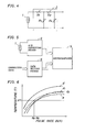
- Fig. 1 is a circuit diagram showing a typical example of the CR oscillator.
- Reference numeral 1 denotes a thermistor.
- a time constant circuit consisting of the thermistor 1 and a capacitor 6, and two CMOS inverters 7 and 8 constitute the CR oscillator.
- the CR oscillator converts to a change in oscillation frequency a change in resistance which is caused by a change in temperature of the thermistor 1.
- an oscillation frequency f is given as follows: where CO is the capacitance of the capacitor 6 and R is the resistance of the thermistor 1.
- the resistance R of the thermistor at a temperature T (K) is derived below: where RO is the resistance of the thermistor at a reference temperature TO (K) and B is the thermistor constant (the thermistor constant will be referred to as the B constant hereinafter) representing the sensitivity given by the temperature-resistance characteristics.
- Equation (3) The number N of pulses generated from the CR oscillator for a unit time t is: Equations (3) and (4) yield the following equation:
- Equation (5) is used to calculate a temperature T upon detection of the number N of pulses from the CR oscillator during the time t.
- the temperature sensitivity characteristic curve of the CR oscillator changes in temperature sensitivity characteristic curve upon use of thermistors with different characteristics, and "linear correction” and “variation correction” of the temperature sensitivity characteristic curve will be described hereinafter.
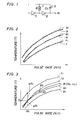
- Fig. 2 is a graph showing temperature sensitivity characteristic curves of thermistors.
- the pulse rate (N/t) of the oscillation signal f0 from the CR oscillator is plotted along the abscissa, and the temperature is plotted along the ordinate.
- a curve a in Fig. 2 shows the standard temperature sensitivity characteristics of a thermistor thermometer using a thermistor having the rated B constant and a capacitor 6 having the rated capacitance C0.
- the standard temperature sensitivity characteristics are defined by equation (5). Curves b and c are obtained when thermistors have the standard resistance but B constants are deviated from the rated values, respectively.
- equation (5) is a monotone increasing function.
- An ambient temperature of the thermistor 1 in the CR oscillator is solely determined by the number N of pulse signals for the predetermined time period t (measuring time).
- the number N of pulses generated by the CR oscillator is counted by a counter.
- the counter can perform only linear incrementation, so that the count cannot be employed as the temperature data without modification. Counting must be performed on the basis of equation (5) to calculate the temperature T. As a result, an expensive operation circuit is required.
- the number N of pulses from the CR oscillator must be counted by a counter having a counting characteristic approximating the curve a of Fig. 2, thereby obtaining the temperature T.
- a simple linearizing circuit is added to the counter to achieve linear correction, and the count of the counter must be used as direct temperature data.
- U.S. Patent No. 4,464,067 issued to the present applicant describes a typical linearizing circuit of this type.
- the linearly corrected results are given by polygonal lines al, bl and cl of Fig. 2 which respectively correspond to the curves a, b and c.
- the polygonal curves a1, bl and cl are obtained without performing variation correction (to be described later), so that their positions and slopes do not change since only linear correction is performed.
- thermometers Variation correction of the thermistors will be described with reference to Fig. 3.
- the temperature sensitivity characteristics of the thermistor depend on two characteristic constants inherent to the thermistor, i.e., the reference resistance RO an the B constant B, as described above.
- the variations in the temperature sensitivity characteristics of the individual thermometers can be accurate when the reference resistance RO and the B constant B of the individual thermistors used in thermistor thermometers are corrected during the fabrication of the thermistor thermometers.
- the temperature T in equation (5) does not change when a product of the reference resistance RO and the capacitance CO of the capacitor is predetermined. This indicates that an error (variation) from the standard resistance RO can be corrected by adjusting the capacitance C0 of the capacitor.
- the capacitor 6 in the CR oscillator of Fig. 1 comprises a variable capacitor, and the capacitance C0 of the capacitor 6 is adjusted so as to correct "variations" in the reference resistance RO of the thermistor 1.
- the resistance RO and the capacitance CO are fixed, and the time t in equation (5) is adjusted. Therefore, the industial "variations" in the capacitance CO in the capacitor 6 in the CR oscillator and "variations" in the reference resistance RO of the thermistor 1 can be simultaneously adjusted.
- Polygonal lines b2 and c2 as the result of correction of the reference resistances are shown in Fig. 3, so that the polygonal lines bl and b2 of Fig. 2 are shifted by ⁇ R1 and ⁇ R2, respectively, thereby correcting them to have the pulse number NO equal to the polygonal line al of the reference temperature sensitivity characteristics at the reference temperature T0.
- Equation (6) varies in accordance with different individual thermistors and presents polygonal lines such as lines b2 and c2, the slopes of which are different due to the different B constants of the individual thermistors from the polygonal line al of the standard temperature sensitivity characteristics.
- the polygonal line b2 is obtained when the error ⁇ of the B constant is positive, while the polygonal line c2 is obtained when the error A is negative.
- the B constant correction (i.e., sensitivity correction) results are represented by polygonal lines b3 and c3 of Fig. 3.
- the characteristics represented by the polygonal lines al, b3 and c3 are rendered identical.
- thermometers As described above, in order to manufacture thermistor thermometers with high productivity at low cost, different characteristics of the thermistors are matched by variation correction with the reference temperature sensitivity characteristics, and a counter having the linear characteristics is used.
- Reference resistance correction is the same as technique (1).
- technique (1) it is very difficult to adjust the resistances of the resistors R1 to R4 for providing predetermined temperature sensitivity characteristics. In addition, adjustment is cumbersome and time-consuming, resulting in low productivity. In spite of such difficulties, ideal characteristics cannot be obtained due to an irregular characteristic curve. Sufficient correction precision for a thermometer cannot be obtained. In addition, when thermometers are automatically manufactured, a compact lightweight thermometer cannot be achieved due to a complex circuit arrangement. As a result, a handy thermistor thermometer at low cost cannot be easily manufactured.
- thermometer device As a whole becomes large and expensive. Therefore, it is difficult to realize a handy, inexpensive thermometer.
- technique (3) correction precision is better than that in technique (1), and the arrangement is simpler and the price is lower than those in technique (2).
- Technique (3) is most suitable for achieving an inexpensive compact thermistor thermometer.
- "variation" correction of the temperature sensitivity characteristics of the thermistor in technique (3) presents the following problem.
- thermometer based on technique (3) reference resistance correction and sensitivity correction are independently performed.
- thermometer having a temperature sensitive oscillator with a variable oscillation frequency which changes in response to a change in resistance of a thermistor, a measuring time signal generator for generating a measuring time signal for sampling and outputting the oscillation signal from the temperature sensitive oscillator, a temperature counter for counting oscillation pulses sampled by the measuring time signal and generating temperature data, a display driver for converting the temperature data to a display signal, and a display device for displaying a temperature in accordance with the display signal, wherein there are provided reference resistance correcting means for controlling to a predetermined reference value the number of oscillation pulses sampled by the measuring time signal at a reference temperature, the reference temperature being given as a constant temperature below a possible operating temperature range, and sensitivity correcting means for causing the thermometer to operate with different counting rates during first and second operating intervals constituting the sampling period of the measuring time signal, switching between the first and second operating intervals of the sensitivity correcting means being controlled in response to
- thermistor thermometer of the present invention The basic operations of the thermistor thermometer of the present invention will be described with reference to the basic arrangement of a thermistor thermometer of Fig. 7 and a graph showing the temperature sensitivity characteristics of Fig. 12.
- a temperature sensitive oscillator 11 of Fig. 7 is the same as that of the thermistor RC oscillator of Fig. 1.
- a time constant of a time constant circuit consisting of a thermistor 1 and a capacitor 6 determines an oscillation frequency of the oscillator 11.
- An oscillation frequency f0 changes in accordance with a change in resistance of the thermistor 1.
- Reference numeral 12 denotes an AND gate which receives as a gate signal a measuring time signal Pt generated by a measuring time signal generator 100.
- the oscillation signal f0 from the temperature sensitive oscillator 11 is supplied as an output pulse signal N to a sensitivity correcting means 102 for a gate signal period.
- the sensitivity correcting means 102 receives as control signals the measuring time signal Pt and a reference count signal Pn0 (to be described later) and divides the sampling period t of the measuring time signal Pt into first and second operating intervals t1 and t2.
- the means 102 generates different count rate output signals fl and f2 during the first and second operating intervals tl and t2, respectively.
- a sum of the signals fl and f2 constitute a counting signal S.
- Reference numeral 16 denotes a temperature counter having a linear function. The temperature counter 16 linearizes the output signals fl and f2 from the sensitivity correction means 102 and counts them to generate temperature data.
- Reference numeral 101 denotes a reference resistance correcting means for setting to the predetermined reference value NO the number of pulses of the oscillation signal sampled in response to the measuring time signal Pt at the reference temperature T0.
- the measuring time signal generator 100 is controlled to control the pulse width of the measuring time signal Pt.
- the oscillation frequency of the temperature oscillator 11 may be controlled by a variable capacitor, as previously described.
- Reference numeral 17 denotes a temperature display circuit which causes a display device 20 to display the temperature data from the temperature counter 16.
- thermometer as a clinical thermometer will be described with reference to the temperature sensitivity characteristic curves of Fig. 12.
- the reference temperature sensitivity characteristics of the thermistor are represented by a curve a, and those of a thermistor actually built into the temperature sensitive oscillator 11 are represented by a curve e.
- the possible operating temperature range can be 32°C to 45°C, and the temperature of 32°C as the lower limit is defined as the reference temperature T0.
- the thermistor thermometer is set in a 32°C thermostat having the reference temperature, and the temperature sensitive oscillator 11 is oscillated at the temperature of 32°C.
- the reference resistance correcting means 101 is adjusted such that the count of the temperature counter 16 is set to be a count SO corresponding to the reference value NO determined by the reference temperature sensitivity characteristic curve a, thereby determining a pulse width t of the measuring time signal Pt.
- the above operation is correction operation of the reference resistance. As shown in Fig. 12, the curve e is shifted to a curve el which crosses the curve a. However, since sensitivity correction is not performed yet, the curve el has an angle of e with respect to the curve a. Subsequently, sensitivity correction is performed such that predetermined correction data is stored in the sensitivity correcting means 102 in accordance with an angle e between the curves a and el.
- a difference between count rates of the sensitivity uncorrected output signal fl and the sensitivity corrected output signal f2 from the sensitivity correction means 102 serves as a sensitivity correction value supplied to the thermistor incorporated in the temperature sensitive oscillator 11.
- the sensitivity correction value varies in accordance with individual thermistors.
- the curve el is shifted to a curve e2 of Fig. 12.
- the curve e2 does not match with the curve a below the temperature range lower than the temperature of 32°C as the reference temperature.
- the curves a and e2 match with each other at the temperature of 32°C. In the range above 32°C, these curves have the identical slope within the possible operating temperature range.
- thermometer having the variation corrected thermistor at 32°C and the operation thereof at a temperature above 32°C will be described below.
- the oscillation output f0(32) from the temperature sensitive oscillator 11 and the noncorrected output signal fl(32) from the sensitivity correcting means 102 have low frequencies in the low temperature operating range of the thermometer.
- the temperature counter 16 starts counting in response to the output signal fl(32).
- the pulse width t of the measuring time signal Pt is determined such that the count of the counter 16 is SO (pulse number NO) at 32°C, a single sampling cycle by the measuring time signal Pt is ended when the count of the temperature counter 16 reaches S0. Therefore, correction is not performed by the sensitivity correcting means, and the sampling period t is the same as the single operating interval of fl(32).
- the thermistor thermometer is operated until the pulse number is given as NO of the curve e2. Counting is performed at sensitivity (the B constant inherent to the thermistor incorporated in the temperature sensitive oscillator 11) different from that given by the curve a.
- thermometer The operation of the thermistor thermometer at a temperature T2 above 32°C will be described hereinafter.
- an oscillation output f0(T2) from the temperature sensitive oscillator 11 and an output signal fl(T2) from the sensitivity correcting means 102 have higher frequencies than those of the outputs f0(32) and fl(32) at 32°C, respectively.
- the temperature counter 16 is started in response to the output signal fl(T2). The same operation as that at 32°C is performed until the count reaches S0. However, when the count of the counter 16 reaches S0, the counter 16 supplies a reference value count signal Pn0 to the sensitivity correcting means 102 which is then operated to switch the output signal from fl(T2) to f2(T2). As a result, the temperature counter 16 is operated in response to the signal f2(T2) after the count SO (the pulse number NO). When the count reaches the pulse number N2, one sampling cycle is completed.
- the sampling period is divided by the measuring time signal Pt into a first interval for which the temperature counter 16 is operated in response to the output signal fl and a second interval for which the temperature counter 16 is operated in response to the signal f2.
- the first and second operating intervals are switched over in response to the . reference count signal Pn0 from the temperature counter 16.
- the above operation is described with reference to Fig. 12.
- the thermistor thermometer is operated in response to the signal fl(T2) in accordance with the B constant inherent to the thermistor in the same manner as at 32°C for the first operating interval between starting of measurement and time corresponding to the pulse number N0.
- the thermistor thermometer is operated in response to the sensitivity corrected signal f2(T2) for the second operating interval between the number NO and the number N2 in accordance with the same sensitivity characteristics as in the curve a.
- Fig. 8 is a block diagram showing an embodiment of the present invention.
- the same reference numerals as in Fig. 8 denote the same parts as in Fig. 7, and a detailed description thereof will be omitted.
- a measuring time signal generator 100 comprises a reference time signal generator 15 and a gate counter 13 for dividing the frequency of a reference pulse signal fs generated by the generator 15 and generating a measuring time signal Pt.
- a sensitivity correcting means 102 comprises a variable frequency divider 14 for dividing the frequency of the output pulse signal from a temperature sensitive oscillator 11, a frequency division ratio conversion read-only memory (to be referred to as a frequency division ratio conversion ROM hereinafter) for converting a frequency division ratio of the variable frequency divider 14 in accordance with the measuring time signal Pt and the reference count signal Pn0 from the temperature counter 16, and an external setting means 19 for setting sensitivity correction data in accordance with the B constant of the thermistor which is built into the temperature sensitive oscillator 11.
- the reference resistance correction means 101 is arranged to adjust a variable capacitor in the temperature sensitive oscillator 11.
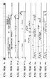
- thermometer having the arrangement described above will be described with reference to temperature sensitivity graphs of Figs. 13 and 14 and the timing charts of Figs. 11(a) to 11(e).
- thermometer having a thermistor of sensitivity deviated in the positive direction and given by a curve b with respect to the reference temperature sensitivity curve a and a thermistor thermometer having a thermistor of sensitivity deviated in the negative direction and given by a curve c.
- the thermistor thermometers In order to correct the reference resistance, the thermistor thermometers is kept in an atmosphere at the reference temperature T0, as previously described. Under this condition, the variable capacitors in the respective thermistor thermometers are adjusted to match the count of the temperature counter 16 with SO (the pulse number NO).
- the variable frequency divider 14 cannot be controlled by the frequency division ratio conversion ROM 18 and is operated at the reference frequency division ratio.
- a frequency division ratio variable corresponding to deviations and their directions (i.e., deviations 81 and 82 and their directions) of sensitivities given by the curves b and c with respect to the curve a are set by the external setting means 19 in the frequency division ratio conversion ROM 18.
- the set frequency division ratio is small in the curve b of high sensitivity with respect to the curve a, but is large in the curve c of low sensitivity with respect to the curve a.
- Fig. 14 shows polygonal lines al, bl and cl obtained by linearly approximating the curves a, b and c of Fig. 13 by a linearizing circuit arranged in the temperature counter 16.
- the pulse rate (N/t) of the pulses sampled by the measuring time signal Pt is plotted along the abscissa, and the counts S of equal temperature interval differences of the counter 16 are plotted along the ordinate.
- Values SO to S4 correspond to the equal interval difference temperatures TO to T4, respectively.
- the frequency division ratio of the variable frequency divider 14 is controlled so as to obtain an identical value of the counts S at the identical temperature with respect to the polygonal lines al, bl and cl.
- the respective frequency division ratio conversion ROMs are set such that the pulse number Nb of the polygonal line bl corresponding to the temperature Tl is equal to the pulse number Nc of the polygonal line cl.
- the number of input pulses supplied to the variable frequency divider 14 is set to be Nb, the number of output pulses therefrom is set to be Sl.
- the frequency division ratio is set such that the number of output pulses from the variable frequency divider 14 is set to be Sl.
- Fig. 11(a) shows the oscillation signal f0 from the temperature sensitive oscillator 11. Different oscillation signals f0 have different frequencies.
- Fig. 11(b) shows the measuring time signal Pt, and its measuring period t is divided into the first and second operating intervals tl and t2. Switching between the first and second operating intervals tl and t2 is controlled in response to the reference count signal Pn0 shown in Fig. 11(c).
- Figs. 11(d) and 11(e) show output pulse signals S(fl+f2) from the variable frequency divider 14.
- Fig. 11(d) shows the signal corresponding to the polygonal line cl of Fig. 14, so that the second operating interval t2 is subjected to operation at a frequency division ratio smaller than the reference frequency division ratio, as compared with the first operating interval tl subjected to operation at the reference frequency division ratio.
- the measuring time signal Pt shown in Fig. 11(b) has a waveform corresponding to the polygonal line cl.
- the first and second operating intervals tl and t2 are controlled by the reference count signal Pn0(c) on the polygonal line cl.
- 11(e) shows the signal corresponding to the polygonal line bl of Fig. 14.
- the second operating interval t2 is subjected to operation at a ratio larger than the reference frequency division ratio, as compared with the first operating interval tl subjected to operation at the reference frequency division ratio.
- the signal frequency fl(b) of the polygonal line bl at the reference frequency division ratio has a higher frequency than that of fl(c) of the polygonal line cl, so that the reference count signal Pn0(b) is generated earlier than Pn0(c) of the polygonal line cl as shown in Fig. 11 (c).
- switching between the first and second operating intervals t1 and t2 is performed.
- the output pulse signals Sc[fl(c)+f2(c)] and Sb[fl(b)+f2(b)] shown in Figs. 11(d) and 11 (e) have the same pulse number at the identical temperature.
- the measuring time signal Pt is generated by the measuring time signal generator 100, and the AND gate 12 is turned on thereby.
- the frequency division ratio conversion ROM 18 is initialized to set the variable frequency divider 14 to be the reference frequency division ratio.
- the output pulse signal N from the AND gate 12 gating the oscillation signal f0 from the temperature sensitive oscillator 11 is reference divided by the variable frequency divider 14, as shown in Fig. 11(d) or 11(e).
- the output pulse signal fl is linearized by the temperature counter 16, so that the counter 16 is started.
- the variable frequency divider 14 changes the set frequency division ratio.
- the variable frequency divider 14 is switched to the second operating interval, as shown in Fig. 11 (d) or (e), and the output pulse signal f2 having a count rate different from that of the pulse signal fl is generated in accordance with the set frequency division ratio, thereby performing sensitivity correction.
- the above-mentioned sensitivity correction is performed for all counts including the counts S2, S3 and S4 of Fig. 14.
- the polygonal lines bl and cl completely match with the polygonal line al.
- the AND gate 12 is disabled to complete one measuring cycle. At this time, the count of the temperature counter 16 is displayed on a display device 20 through a temperature display circuit 17.
- Fig. 9 is a block diagram showing another embodiment of the present invention.
- a NAND gate 22 in place of the AND gate 12 of Fig. 8 is arranged in a temperature sensitive oscillator 21.
- a measuring time signal from a gate counter 13 is used as a gate signal of the NAND gate 22 which is then enabled, so that the oscillator 21 can be operated only for the measuring time signal interval.
- the oscillation period is changed in correspondence with the measuring time signal period t to control the number of pulses supplied from the temperature sensitive oscillator 21 to the temperature counter 16, thereby obtaining the counting characteristics represented by al, bl or cl of Fig. 14.
- the temperature sensitive oscillator 21 is operated only for the necessary measuring time, the driving power of the oscillator 21 can be greatly saved.
- the thermometer is operated with a compact dry cell, the above arrangement can be conveniently used.
- a means for varying the oscillation frequency is included as a reference resistance correcting means 101 in a time reference signal generator 23.
- the time reference signal generator 23 is constituted by a CR oscillator, and a variable resistor is used as the oscillation frequency varying means in a time constant circuit for determining the oscillation frequency.
- the variable resistance 24 is operated to adjust the frequency of the reference signal supplied from the time reference signal generator 23 to the gate counter 13.
- the interval of the measuring time signal Pt from the gate counter 13 is variable.
- the output pulse signal supplied from the temperature sensitive oscillator 21 to the temperature counter 16 can be adjusted to have a predetermined frequency. This arrangement is advantageous in mass production so as to correct "variations" in temperature sensitivity characteristics based on different reference resistances of the thermistor as described with reference to Fig. 3 since the variable resistor is used. As compared with the case of the variable capacitor of Fig. 2, the circuit arrangement and adjustment can be simplified.
- the temperature display circuit 17 has a known circuit arrangement consisting of a maximum temperature memory 25 and a display driver 26.
- Fig. 10 is a block diagram showing still another embodiment in which a linearizing circuit is added to the arrangement of Fig. 9.
- the temperature counter 16 comprises a counter 16a and a linearizing circuit 16b.
- the output pulse signal f0 from a temperature sensitive oscillator 21 is supplied to the counter 16a through the linearizing circuit 16b.
- the temperature sensitivity characteristics of the oscillator 21 can be linearized by the linearizing circuit 16b for performing linear approximation. Temperature measurement precision can be improved in accordance with correction of the "variations" based on the different types of thermistors.
- the linearizing circuit 16b is arranged in accordance with a technique described in detail in U.S.P. No. 4,464,067 issued to the present applicant.
- the linearizing circuit 16b is inserted between the counter 16a and a variable frequency divider 14 constituting the sensitivity correcting means 102.
- the circuit 16b comprises a variable frequency divider 28 for dividing the output pulse signal S from the variable frequency divider 14, a polygonal line approximation range frequency divider 29 for dividing the frequency of the frequency-divided pulse signal supplied from the variable frequency divider 28 to the counter 16a, an address counter 30 for counting outputs from the frequency divider 29, and a frequency division ratio conversion ROM 31 for controlling a frequency division ratio of the variable frequency divider 28 so as to obtain a frequency division ratio corresponding to the count in accordance with a preset program.
- the output pulse number n for the unit measuring time t from the temperature sensitive oscillator 21 does not linearly change with respect to the temperature T, as described with reference to Fig. 2.
- the sensitivity is degraded when the temperature T is increased. In order to improve the measuring precision, the characteristics must be linearized.
- An output from the temperature sensitive oscillator 21 is frequency-divided by the variable frequency divider 28 in the counter 16b, and the frequency-divided signal is supplied to the polygonal line approximation range frequency divider 29.
- the frequency divider 29 generates input pulses one by one for every temperature interval difference in accordance with the characteristics associated with the B constant of the thermistor 1 in the temperature sensitive oscillator 21.
- Fig. 15 is a block diagram showing still another embodiment of the present invention. Unlike in the embodiment of Fig. 2 wherein the sensitivity correcting means 102 is inserted between the temperature sensitive oscillator 11 and the temperature counter 16 to vary the frequency of the oscillation signal f0 from the temperature sensitive oscillator 11, a sensitivity correcting means 102 is arranged between a time reference signal generator 15 and a gate counter 13 to vary a frequency fs from the time reference signal generator 15, thus varying the period of the measuring time signal Pt.
- thermistors having the temperature sensitivity characteristics given by the curves b and c of Fig. 13 matches with the reference characteristic curve a.
- the thermistor thermometers are kept in an atmosphere at the reference temperature T0, and the variable frequency divider 14 in the sensitivity correcting means 102 is held at the frequency frequency division ratio.
- reference resistance correcting means such as a variable capacitor in the temperature sensitive oscillator 11 and a variable resistor in the time reference signal generator 15 are adjusted to match the count of a temperature counter 16 with a reference count S0. Therefore, a frequency of the reference pulse signal fs from the time reference signal generator 15 and a pulse number NO at the reference temperature TO are determined.
- a frequency division ratio variable is set by an external setting means 19 in a frequency division ratio conversion ROM 18 in accordance with deviations and their directions (i.e., deviations ⁇ 1 and 02 and their directions) of the curves b and c with respect to the reference temperature sensitivity characteristic curve a.
- the set frequency division ratio is small for the curve b of high sensitivity with respect to the curve a and is large for the curve c of low sensitivity with respect to the curve a.
- Fig. 16(a) shows the reference pulse signal fs from the time reference signal generator 15. After reference resistance correction is performed, the reference pulse signal fs has a predetermined frequency.
- Figs. 16(b), 16(c) and 16(d) show measuring time signals Pt(a), Pt(b) and Pt(c) corresponding to the polygonal lines al, bl and cl, respectively. These signals have different sampling periods t(a), t(b) and t(c), respectively. Each sampling period is divided into first and second operating intervals t1 and t2.
- Fig. 16(e) shows the reference count signal PnO.
- the reference count signals Pn0(a), Pn0(b) and Pn0(c) corresponding to the polygonal lines al, bl and cl control switching between the first and second operating intervals t1 and t2 of the measuring time signals Pt(a), Pt(b) and Pt(c) respectively shown in Figs. 16(b), 16(c) and 16(d).
- Figs. 16(f), 16 (g) and 16 (h) respectively show output pulse signals M(fl+f2) from the variable frequency divider 14.
- Fig. 16(f) shows an output pulse signal Ma corresponding to the polygonal line al. The first and second operating intervals of the signal Ma are subjected to operation at the frequency fl based on the reference frequency division ratio from the variable frequency divider 14.
- Fig. 16(g) shows an output pulse signal Mb corresponding to the polygonal line bl. The first operating interval of the signal Mb is subjected to operation at the frequency fl based on the reference frequency division ratio of the variable frequency divider 14.
- the second operating interval of the signal Mb is subjected to operation at the frequency f2(b) based on the frequency division ratio set by the ROM 18.
- Fig. 16(h) shows an output pulse signal Mc corresponding to the polygonal line cl.
- the first operating interval of the signal Mc is subjected to operation at the frequency fl based on the reference frequency division ratio, but the second operating interval thereof is subjected to operation at the frequency f2(c) based on the frequency division ratio set by the ROM 18.
- the relationship between the frequencies fl, f2, f2(b) and f2(c) is determined to be f2(c) ⁇ fl ⁇ f2(b) such that the frequency division ratio set in the ROM 18 is small for the curve b and large for the curve c with reference to the reference frequency division ratio.
- thermometers respectively with thermistors of the temperature sensitivity characteristic curves a, b and c in the temperature range above the reference temperature TO will be described hereinafter.
- thermometer having the thermistor of the reference temperature sensitivity characteristic curve a
- sensitivity correction need not be performed, and the frequency division ratio need not be updated in the ROM 18.
- the variable frequency divider 14 is always operated at the reference frequency division ratio.
- the AND gate 12 is enabled in response to the measuring time signal Pt(a) from the gate counter 13, as shown in Fig. 16(b).
- the ROM 18 is initialized, and the variable frequency divider 14 is operated at the reference frequency division ratio.
- An output pulse signal N gated through the AND gate 12 which receives the oscillation signal f0(a) from the temperature sensitive oscillator 11 is linearized as a count signal S by the temperature counter 16. In this case, the temperature counter 16 is started.
- the output pulse signal Ma from the variable frequency divider 14 is counted by the gate counter 13 at the reference frequency-divided frequency fl.
- the temperature counter 16 When the count of the temperature counter 16 reaches SO corresponding to the reference value N0, the temperature counter 16 generates the reference count signal Pn0(a) shown in Fig. 16(e), so that the ROM 18 is switched in the correction value setting state.
- the variable frequency divider 14 is thus operated at the set frequency division ratio. As shown in Fig. 16(b), the above operation corresponds to the first operating interval tl(a).
- the first operating interval tl is switched to the second operating interval t2.
- variable frequency divider 14 is kept operated at the reference frequency division ratio.
- the frequency divider 14 generates the signal fl as the output pulse signal Ma.
- the gate counter 13 counts the predetermined number G of pulses which is determined by the number of stages of the gate counter 13, the measuring time signal Pt(a) shown in Fig. 16(b) is disabled, the AND gate 12 is disabled, and one measurement cycle is completed.
- the above operation will be described with reference to Fig. 14.
- the first operating interval tl(a) of the measuring time signal Pt(a) of Fig. 16(b) is the count interval for the reference value NO of the temperature counter 16
- the second operating interval t2(a) is the count interval between the reference value NO and the end value Na. Therefore, when the temperature counter 16 counts the number Na of pulses, it generates the count Sl.
- Sensitivity correction is not required for the thermistor of the reference temperature sensitivity characteristic curve a.
- the sampling period t(a) constituted by the first and second operating intervals tl(a) and t2(a) is determined by the output pulse signal Ma having the reference frequency fl of the same rate.
- the period t(a) is the reference sampling period.
- thermometer incorporating a thermistor of positively deviated sensitivity given by the curve b When the thermometer incorporating a thermistor of positively deviated sensitivity given by the curve b is used, a frequency division ratio smaller than the reference frequency division ratio is set in the frequency d ratio convertion ROM 18, as described above.
- the characteristic curve in the first operating interval tl(b) is the same as the curve a until the interval tl(b) ends. Thereafter, since the oscillation frequency f0 of the temperature sensitive oscillator 11 has a higher frequency than that given by the curve a, the counting timing of the temperature counter 16 for counting the reference value NO is set to be earlier. As shown in Fig. 16(e), the reference count signal Pn0(b) is generated earlier than the signal Pn0(a), so that the first operating interval tl(b) is shorter than the interval tl(a).
- the output pulse signal Mb during the second operating interval t2(b) has the higher frequency f2(b).
- the pulse number G counting time of the gate counter 13 is shortened.
- the sampling period t(b) of the measuring time signal Pt(b) is shortened by ⁇ t1 as compared with the reference sampling period t(a).
- the above operation will be described with reference to Fig. 14.
- the oscillation signal f0(b) from the temperature sensitive oscillator 11 with the curve b has a higher frequency than that of the oscillation signal f0(a) represented by the curve a.
- the number of pulses generated during the reference sampling period t(a) is Nb.
- the first and second intervals tl(b) and t2(b) are subjected to operations by signals f1 and f2(b) having different count rates, thereby changing the sampling period t(b) of the measuring time signal Pt(b) and hence performing sensitivity correction.
- the above sensitivity correction is performed for all counts including the counts S2, S3 and S4 of Fig. 14.
- the polygonal line bl completely matches with the polygonal line al.
- a frequency division ratio larger than the reference frequency division ratio is set in the ROM 18. As shown in Figs. 16(d) and 16(h), the sampling time t(c) is increased by ⁇ t2 from the reference sampling period t(a).
- the oscillation signal f0(c) from the temperature sensitive oscillator 11, as indicated by the curve c of Fig. 14, has a lower frequency than that of the oscillation signal f0(a) of the curve a, so that the number of pulses generated during the reference sampling period t(a) is Nc.
- the number of pulses supplied to the temperature counter 16 is increased to Na, thereby obtaining the same count Sl as in the curve a.
- Fig. 17 shows still another embodiment.
- the arrangement of Fig. 17 is basically the same as that of Fig. 15.
- the reference resistance correction is performed by a variable resistor 24 arranged in the reference signal generator 15.
- a linearizing circuit 16b of Fig. 4 is arranged in the temperature counter 16.
- the sampling period of the temperature measurement is divided into the first and second operating intervals subjected to operations at different count rates.
- reference resistance correction is performed during the first operating interval, and sensitivity correction is performed during the second operating interval.
- the reference resistance and the B constant which cause variations in the thermistor temperature sensitivity characteristics can be independently adjusted.
- the characteristic matching operation in the mass production lines of the thermistor thermometers can be greatly simplified.
- sensitivity correction is performed only for the necessary operation temperature range. Furthermore, the correction direction in sensitivity correction can be either negative or positive, so that the arrangement of the correction circuit can be simplified. Furthermore, by adding a linearizing circuit to a thermistor thermometer, thermistor thermometers of high temperature measurement precision and small "variations" in characteristics can be manufactured at low cost in mass production lines.
Landscapes
- Physics & Mathematics (AREA)
- Nonlinear Science (AREA)
- General Physics & Mathematics (AREA)
- Measuring Temperature Or Quantity Of Heat (AREA)
- Indication And Recording Devices For Special Purposes And Tariff Metering Devices (AREA)
Applications Claiming Priority (4)
| Application Number | Priority Date | Filing Date | Title |
|---|---|---|---|
| JP22273584A JPS61100624A (ja) | 1984-10-23 | 1984-10-23 | サ−ミスタ温度計の補正方法 |
| JP222735/84 | 1984-10-23 | ||
| JP22273684A JPS61100625A (ja) | 1984-10-23 | 1984-10-23 | サ−ミスタ温度計の補正方法 |
| JP222736/84 | 1984-10-23 |
Publications (3)
| Publication Number | Publication Date |
|---|---|
| EP0180393A2 true EP0180393A2 (fr) | 1986-05-07 |
| EP0180393A3 EP0180393A3 (en) | 1987-05-13 |
| EP0180393B1 EP0180393B1 (fr) | 1990-05-02 |
Family
ID=26525049
Family Applications (1)
| Application Number | Title | Priority Date | Filing Date |
|---|---|---|---|
| EP85307603A Expired - Lifetime EP0180393B1 (fr) | 1984-10-23 | 1985-10-22 | Thermomètre à thermistance |
Country Status (3)
| Country | Link |
|---|---|
| US (1) | US4602871A (fr) |
| EP (1) | EP0180393B1 (fr) |
| DE (1) | DE3577477D1 (fr) |
Families Citing this family (50)
| Publication number | Priority date | Publication date | Assignee | Title |
|---|---|---|---|---|
| JPS61167827A (ja) * | 1985-01-21 | 1986-07-29 | Omron Tateisi Electronics Co | 電子温度計 |
| JPS62240824A (ja) * | 1986-04-11 | 1987-10-21 | Sharp Corp | 温度計 |
| JPS6439502A (en) * | 1987-08-05 | 1989-02-09 | Man Design Co | Length measuring instrument |
| US5046859A (en) * | 1988-06-17 | 1991-09-10 | Ricoh Company, Ltd. | Temperature measuring device and thermal head device having the same |
| US5031126A (en) * | 1988-06-30 | 1991-07-09 | Delta M Corporation | Constant power thermal sensor |
| US5116136A (en) * | 1989-06-01 | 1992-05-26 | Massachusetts Institute Of Technology | Temperature measurements using thermistor elements |
| US5321638A (en) * | 1990-04-30 | 1994-06-14 | Witney Keith C | Calibrated sensor systems and methods of manufacturing same |
| JP2971924B2 (ja) | 1990-08-22 | 1999-11-08 | 旭光学工業株式会社 | カメラシステム |
| US5137370A (en) * | 1991-03-25 | 1992-08-11 | Delta M Corporation | Thermoresistive sensor system |
| US5638418A (en) * | 1993-02-05 | 1997-06-10 | Dallas Semiconductor Corporation | Temperature detector systems and methods |
| US5552999A (en) * | 1991-07-09 | 1996-09-03 | Dallas Semiconductor Corp | Digital histogram generator systems and methods |
| US5388134A (en) * | 1993-02-05 | 1995-02-07 | Dallas Semiconductor Corporation | Integrated circuit thermometer |
| US5249866A (en) * | 1992-05-29 | 1993-10-05 | The United States Of America As Represented By The Secretary Of Commerce | Thermal properties measurement using a superconductor sensor |
| US5725308A (en) * | 1994-12-23 | 1998-03-10 | Rtd Technology, Inc. | Quick registering thermometer |
| US5614716A (en) * | 1996-04-26 | 1997-03-25 | Infratemp, Inc. | Alternating current method and apparatus for ambient temperature compensation for modulated energy sensors |
| US5774425A (en) * | 1996-11-15 | 1998-06-30 | The University Of British Columbia | Time monitoring appliance |
| US6058356A (en) * | 1998-04-30 | 2000-05-02 | Cooper Instrument Corporation | Hand-held electronic instrument |
| US6390672B1 (en) * | 2000-01-20 | 2002-05-21 | Harris Corporation | Space vehicle with temperature sensitive oscillator and associated method of sensing temperature in space |
| US6900721B1 (en) | 2000-02-11 | 2005-05-31 | Bio Medic Data Systems, Inc. | Implantable inductively programmed temperature sensing transponder |
| US6773405B2 (en) | 2000-09-15 | 2004-08-10 | Jacob Fraden | Ear temperature monitor and method of temperature measurement |
| JP4001551B2 (ja) * | 2000-12-12 | 2007-10-31 | ミニ−ミッター カンパニー,インコーポレイテッド | 温度計及び温度計の製造方法 |
| US6695475B2 (en) * | 2001-05-31 | 2004-02-24 | Stmicroelectronics, Inc. | Temperature sensing circuit and method |
| US6839651B2 (en) | 2001-06-27 | 2005-01-04 | Sherwood Services Ag | Probe tip thermal isolation and fast prediction algorithm |
| US6914764B2 (en) * | 2002-07-11 | 2005-07-05 | International Business Machines Corporation | On-chip thermal sensing circuit |
| US6874933B1 (en) * | 2002-10-15 | 2005-04-05 | National Semiconductor Corporation | Apparatus for digital temperature measurement in an integrated circuit |
| US7044633B2 (en) * | 2003-01-09 | 2006-05-16 | International Business Machines Corporation | Method to calibrate a chip with multiple temperature sensitive ring oscillators by calibrating only TSRO |
| US6814485B2 (en) * | 2003-01-23 | 2004-11-09 | Sun Microsystems, Inc. | On-die thermal monitoring technique |
| US20040190585A1 (en) * | 2003-03-27 | 2004-09-30 | International Business Machines Corporation | Method to calibrate a temperature sensitive ring oscillator with minimal test time |
| US7938783B2 (en) * | 2003-08-19 | 2011-05-10 | Advanced Monitors Corporation | Medical body core thermometer |
| US7785266B2 (en) | 2003-08-19 | 2010-08-31 | Advanced Monitors Corporation | Medical thermometer for determining body core temperature |
| KR100576480B1 (ko) * | 2003-12-26 | 2006-05-10 | 주식회사 하이닉스반도체 | 온도 센서용 오실레이터 회로 |
| KR100677742B1 (ko) * | 2004-07-23 | 2007-02-02 | 삼성전자주식회사 | 디지털 온도 센서, 디지털 온도 측정 시스템 및 방법 |
| US7250777B2 (en) * | 2005-03-30 | 2007-07-31 | Mini-Mitter Co., Inc. | Method and device for measuring resistance |
| US7316507B2 (en) * | 2005-11-03 | 2008-01-08 | Covidien Ag | Electronic thermometer with flex circuit location |
| US20070100253A1 (en) * | 2005-11-03 | 2007-05-03 | Sherwood Services Ag | Electronic thermometer with sensor location |
| US7507019B2 (en) * | 2006-05-19 | 2009-03-24 | Covidien Ag | Thermometer calibration |
| US20070268952A1 (en) * | 2006-05-19 | 2007-11-22 | Sherwood Services Ag | Thermometer calibration by immersion in non-electrically conductive liquid |
| US20070268954A1 (en) * | 2006-05-19 | 2007-11-22 | Sherwood Services Ag | Portable test apparatus for radiation-sensing thermometer |
| US20080043809A1 (en) * | 2006-08-18 | 2008-02-21 | Herbert Curtis B | Thermometer |
| US7549792B2 (en) | 2006-10-06 | 2009-06-23 | Covidien Ag | Electronic thermometer with selectable modes |
| EP2083254B1 (fr) * | 2006-10-09 | 2018-07-18 | Incide, S.a. | Capteur de température sans fil |
| TWI310456B (en) * | 2006-12-06 | 2009-06-01 | Via Tech Inc | Digital temperature detecting system and detecting method |
| US7749170B2 (en) | 2007-05-22 | 2010-07-06 | Tyco Healthcare Group Lp | Multiple configurable electronic thermometer |
| US8496377B2 (en) | 2007-12-31 | 2013-07-30 | Covidien Lp | Thermometer having molded probe component |
| TWI372855B (en) * | 2008-05-27 | 2012-09-21 | Nanya Technology Corp | Temperature detector and the method using the same |
| US8478558B2 (en) * | 2008-12-18 | 2013-07-02 | Kohler Co. | Method for processing a temperature sensor signal |
| US8229056B2 (en) * | 2010-12-17 | 2012-07-24 | Nxp B.V. | Universal counter/timer circuit |
| KR20140025069A (ko) * | 2012-08-21 | 2014-03-04 | 현대자동차주식회사 | 실차 특성을 반영한 연료전지 파워 모듈 평가를 위한 모터 출력 모사 장치 |
| CN114689199B (zh) * | 2020-12-29 | 2023-06-02 | 华润微集成电路(无锡)有限公司 | 实现温度补偿的预测型电子体温计电路结构 |
| CN113532680A (zh) * | 2021-06-03 | 2021-10-22 | 上海润欣科技股份有限公司 | 体温计芯片和体温计 |
Citations (3)
| Publication number | Priority date | Publication date | Assignee | Title |
|---|---|---|---|---|
| US4370070A (en) * | 1981-02-13 | 1983-01-25 | General Electric Company | Digital thermometer having Fahrenheit and Celsius readout modes |
| JPS5815134A (ja) * | 1981-07-20 | 1983-01-28 | Omron Tateisi Electronics Co | 電子温度計 |
| GB2118307A (en) * | 1982-01-22 | 1983-10-26 | Citizen Watch Co Ltd | Thermistor thermometer |
Family Cites Families (5)
| Publication number | Priority date | Publication date | Assignee | Title |
|---|---|---|---|---|
| US3287975A (en) * | 1963-04-12 | 1966-11-29 | Pyrotel Corp | Temperature indicator |
| DE2209770C3 (de) * | 1972-03-01 | 1980-07-24 | Philips Patentverwaltung Gmbh, 2000 Hamburg | Schaltungsanordnung zur Umwandlung des exponentiell mit einer Meßgröße verknüpften Widerstandswerts eines Widerstandsgebers in eine der Meßgröße proportionale Frequenz einer elektrischen Schwingung |
| CA1175677A (fr) * | 1981-04-03 | 1984-10-09 | Stephen A. Briggs | Compensation en temperature pour circuits en pont |
| US4453835A (en) * | 1982-05-03 | 1984-06-12 | Clawson Burrell E | Temperature sensor |
| NL8302593A (nl) * | 1983-07-20 | 1985-02-18 | Enraf Nonius Delft | Inrichting voor het meten van de temperatuur. |
-
1985
- 1985-10-22 EP EP85307603A patent/EP0180393B1/fr not_active Expired - Lifetime
- 1985-10-22 DE DE8585307603T patent/DE3577477D1/de not_active Expired - Fee Related
- 1985-10-22 US US06/790,295 patent/US4602871A/en not_active Expired - Lifetime
Patent Citations (3)
| Publication number | Priority date | Publication date | Assignee | Title |
|---|---|---|---|---|
| US4370070A (en) * | 1981-02-13 | 1983-01-25 | General Electric Company | Digital thermometer having Fahrenheit and Celsius readout modes |
| JPS5815134A (ja) * | 1981-07-20 | 1983-01-28 | Omron Tateisi Electronics Co | 電子温度計 |
| GB2118307A (en) * | 1982-01-22 | 1983-10-26 | Citizen Watch Co Ltd | Thermistor thermometer |
Non-Patent Citations (1)
| Title |
|---|
| PATENTS ABSTRACTS OF JAPAN, vol. 7, no. 90 (P-191)[1235], 14th April 1983; & JP-A-58 015 134 (TATEISHI DENKI K.K.) 28-01-1983 * |
Also Published As
| Publication number | Publication date |
|---|---|
| EP0180393B1 (fr) | 1990-05-02 |
| US4602871A (en) | 1986-07-29 |
| DE3577477D1 (en) | 1990-06-07 |
| EP0180393A3 (en) | 1987-05-13 |
Similar Documents
| Publication | Publication Date | Title |
|---|---|---|
| US4602871A (en) | Thermistor thermometer | |
| US4150573A (en) | Electronic digital thermometer | |
| US4210024A (en) | Temperature measurement apparatus | |
| US5216599A (en) | Method of processing data for determining the time of ovulation in an animal | |
| US4015208A (en) | Frequency generator compensated as a function of at least one physical parameter of the environment | |
| US5001657A (en) | Radiation thermometer | |
| JPH112571A (ja) | 温度測定方法及び低消費電流で作動する温度測定装置 | |
| US4110746A (en) | A-D converter having nonlinear characteristics | |
| US4117722A (en) | Measuring apparatus providing separate analog and digital outputs | |
| US4794320A (en) | Multi-frequency capacitance sensor | |
| US4370070A (en) | Digital thermometer having Fahrenheit and Celsius readout modes | |
| US20040057494A1 (en) | Ear thermometer with improved temperature coefficient and method of calibration thereof | |
| US4563748A (en) | Temperature measuring system | |
| JPH0333213B2 (fr) | ||
| GB2157515A (en) | Electronic thermometer | |
| US4844623A (en) | Electronic thermometer | |
| GB2084329A (en) | Electronic Thermometer | |
| JPS6273130A (ja) | サ−ミスタ温度計 | |
| JP2003028726A (ja) | 電子体温計 | |
| JPH0471172B2 (fr) | ||
| JPS6260656B2 (fr) | ||
| JPS5895230A (ja) | 電子式温度測定方法及び装置 | |
| JPS61100625A (ja) | サ−ミスタ温度計の補正方法 | |
| JPH0261697B2 (fr) | ||
| JPH0367209B2 (fr) |
Legal Events
| Date | Code | Title | Description |
|---|---|---|---|
| PUAI | Public reference made under article 153(3) epc to a published international application that has entered the european phase |
Free format text: ORIGINAL CODE: 0009012 |
|
| AK | Designated contracting states |
Kind code of ref document: A2 Designated state(s): BE DE FR GB NL |
|
| PUAL | Search report despatched |
Free format text: ORIGINAL CODE: 0009013 |
|
| AK | Designated contracting states |
Kind code of ref document: A3 Designated state(s): BE DE FR GB NL |
|
| 17P | Request for examination filed |
Effective date: 19870915 |
|
| 17Q | First examination report despatched |
Effective date: 19890419 |
|
| GRAA | (expected) grant |
Free format text: ORIGINAL CODE: 0009210 |
|
| AK | Designated contracting states |
Kind code of ref document: B1 Designated state(s): BE DE FR GB NL |
|
| ET | Fr: translation filed | ||
| REF | Corresponds to: |
Ref document number: 3577477 Country of ref document: DE Date of ref document: 19900607 |
|
| PLBE | No opposition filed within time limit |
Free format text: ORIGINAL CODE: 0009261 |
|
| STAA | Information on the status of an ep patent application or granted ep patent |
Free format text: STATUS: NO OPPOSITION FILED WITHIN TIME LIMIT |
|
| 26N | No opposition filed | ||
| REG | Reference to a national code |
Ref country code: GB Ref legal event code: IF02 |
|
| PGFP | Annual fee paid to national office [announced via postgrant information from national office to epo] |
Ref country code: FR Payment date: 20031003 Year of fee payment: 19 |
|
| PGFP | Annual fee paid to national office [announced via postgrant information from national office to epo] |
Ref country code: NL Payment date: 20031008 Year of fee payment: 19 |
|
| PGFP | Annual fee paid to national office [announced via postgrant information from national office to epo] |
Ref country code: GB Payment date: 20031022 Year of fee payment: 19 |
|
| PGFP | Annual fee paid to national office [announced via postgrant information from national office to epo] |
Ref country code: DE Payment date: 20031030 Year of fee payment: 19 |
|
| PGFP | Annual fee paid to national office [announced via postgrant information from national office to epo] |
Ref country code: BE Payment date: 20031211 Year of fee payment: 19 |
|
| PG25 | Lapsed in a contracting state [announced via postgrant information from national office to epo] |
Ref country code: GB Free format text: LAPSE BECAUSE OF NON-PAYMENT OF DUE FEES Effective date: 20041022 |
|
| PG25 | Lapsed in a contracting state [announced via postgrant information from national office to epo] |
Ref country code: BE Free format text: LAPSE BECAUSE OF NON-PAYMENT OF DUE FEES Effective date: 20041031 |
|
| BERE | Be: lapsed |
Owner name: *CITIZEN WATCH CO. LTD Effective date: 20041031 |
|
| PG25 | Lapsed in a contracting state [announced via postgrant information from national office to epo] |
Ref country code: NL Free format text: LAPSE BECAUSE OF NON-PAYMENT OF DUE FEES Effective date: 20050501 |
|
| PG25 | Lapsed in a contracting state [announced via postgrant information from national office to epo] |
Ref country code: DE Free format text: LAPSE BECAUSE OF NON-PAYMENT OF DUE FEES Effective date: 20050503 |
|
| GBPC | Gb: european patent ceased through non-payment of renewal fee |
Effective date: 20041022 |
|
| PG25 | Lapsed in a contracting state [announced via postgrant information from national office to epo] |
Ref country code: FR Free format text: LAPSE BECAUSE OF NON-PAYMENT OF DUE FEES Effective date: 20050630 |
|
| NLV4 | Nl: lapsed or anulled due to non-payment of the annual fee |
Effective date: 20050501 |
|
| REG | Reference to a national code |
Ref country code: FR Ref legal event code: ST |
|
| BERE | Be: lapsed |
Owner name: *CITIZEN WATCH CO. LTD Effective date: 20041031 |