US7250777B2 - Method and device for measuring resistance - Google Patents
Method and device for measuring resistance Download PDFInfo
- Publication number
- US7250777B2 US7250777B2 US11/391,944 US39194406A US7250777B2 US 7250777 B2 US7250777 B2 US 7250777B2 US 39194406 A US39194406 A US 39194406A US 7250777 B2 US7250777 B2 US 7250777B2
- Authority
- US
- United States
- Prior art keywords
- comparator
- input
- output
- flop
- flip
- Prior art date
- Legal status (The legal status is an assumption and is not a legal conclusion. Google has not performed a legal analysis and makes no representation as to the accuracy of the status listed.)
- Active
Links
- 238000000034 method Methods 0.000 title claims description 12
- 238000005259 measurement Methods 0.000 description 21
- 239000003990 capacitor Substances 0.000 description 10
- 238000013459 approach Methods 0.000 description 5
- 241001465754 Metazoa Species 0.000 description 3
- 230000001419 dependent effect Effects 0.000 description 3
- 238000010586 diagram Methods 0.000 description 3
- 230000000694 effects Effects 0.000 description 3
- 239000006187 pill Substances 0.000 description 3
- 230000032683 aging Effects 0.000 description 2
- 230000008901 benefit Effects 0.000 description 2
- 239000002775 capsule Substances 0.000 description 2
- 239000000463 material Substances 0.000 description 2
- 230000036760 body temperature Effects 0.000 description 1
- 238000009529 body temperature measurement Methods 0.000 description 1
- 238000006243 chemical reaction Methods 0.000 description 1
- 238000012937 correction Methods 0.000 description 1
- 239000013078 crystal Substances 0.000 description 1
- 239000007933 dermal patch Substances 0.000 description 1
- 210000000613 ear canal Anatomy 0.000 description 1
- 230000014509 gene expression Effects 0.000 description 1
- 238000004519 manufacturing process Methods 0.000 description 1
- 238000012544 monitoring process Methods 0.000 description 1
- 230000010355 oscillation Effects 0.000 description 1
Images

Classifications
-
- G—PHYSICS
- G01—MEASURING; TESTING
- G01R—MEASURING ELECTRIC VARIABLES; MEASURING MAGNETIC VARIABLES
- G01R27/00—Arrangements for measuring resistance, reactance, impedance, or electric characteristics derived therefrom
- G01R27/02—Measuring real or complex resistance, reactance, impedance, or other two-pole characteristics derived therefrom, e.g. time constant
- G01R27/14—Measuring resistance by measuring current or voltage obtained from a reference source
-
- G—PHYSICS
- G01—MEASURING; TESTING
- G01D—MEASURING NOT SPECIALLY ADAPTED FOR A SPECIFIC VARIABLE; ARRANGEMENTS FOR MEASURING TWO OR MORE VARIABLES NOT COVERED IN A SINGLE OTHER SUBCLASS; TARIFF METERING APPARATUS; MEASURING OR TESTING NOT OTHERWISE PROVIDED FOR
- G01D5/00—Mechanical means for transferring the output of a sensing member; Means for converting the output of a sensing member to another variable where the form or nature of the sensing member does not constrain the means for converting; Transducers not specially adapted for a specific variable
- G01D5/26—Mechanical means for transferring the output of a sensing member; Means for converting the output of a sensing member to another variable where the form or nature of the sensing member does not constrain the means for converting; Transducers not specially adapted for a specific variable characterised by optical transfer means, i.e. using infrared, visible, or ultraviolet light
- G01D5/32—Mechanical means for transferring the output of a sensing member; Means for converting the output of a sensing member to another variable where the form or nature of the sensing member does not constrain the means for converting; Transducers not specially adapted for a specific variable characterised by optical transfer means, i.e. using infrared, visible, or ultraviolet light with attenuation or whole or partial obturation of beams of light
- G01D5/34—Mechanical means for transferring the output of a sensing member; Means for converting the output of a sensing member to another variable where the form or nature of the sensing member does not constrain the means for converting; Transducers not specially adapted for a specific variable characterised by optical transfer means, i.e. using infrared, visible, or ultraviolet light with attenuation or whole or partial obturation of beams of light the beams of light being detected by photocells
- G01D5/347—Mechanical means for transferring the output of a sensing member; Means for converting the output of a sensing member to another variable where the form or nature of the sensing member does not constrain the means for converting; Transducers not specially adapted for a specific variable characterised by optical transfer means, i.e. using infrared, visible, or ultraviolet light with attenuation or whole or partial obturation of beams of light the beams of light being detected by photocells using displacement encoding scales
- G01D5/3473—Circular or rotary encoders
- G01D5/34738—Axles; Driving or coupling means
-
- G—PHYSICS
- G01—MEASURING; TESTING
- G01K—MEASURING TEMPERATURE; MEASURING QUANTITY OF HEAT; THERMALLY-SENSITIVE ELEMENTS NOT OTHERWISE PROVIDED FOR
- G01K13/00—Thermometers specially adapted for specific purposes
- G01K13/20—Clinical contact thermometers for use with humans or animals
-
- G—PHYSICS
- G01—MEASURING; TESTING
- G01K—MEASURING TEMPERATURE; MEASURING QUANTITY OF HEAT; THERMALLY-SENSITIVE ELEMENTS NOT OTHERWISE PROVIDED FOR
- G01K7/00—Measuring temperature based on the use of electric or magnetic elements directly sensitive to heat ; Power supply therefor, e.g. using thermoelectric elements
- G01K7/16—Measuring temperature based on the use of electric or magnetic elements directly sensitive to heat ; Power supply therefor, e.g. using thermoelectric elements using resistive elements
- G01K7/22—Measuring temperature based on the use of electric or magnetic elements directly sensitive to heat ; Power supply therefor, e.g. using thermoelectric elements using resistive elements the element being a non-linear resistance, e.g. thermistor
- G01K7/24—Measuring temperature based on the use of electric or magnetic elements directly sensitive to heat ; Power supply therefor, e.g. using thermoelectric elements using resistive elements the element being a non-linear resistance, e.g. thermistor in a specially-adapted circuit, e.g. bridge circuit
- G01K7/245—Measuring temperature based on the use of electric or magnetic elements directly sensitive to heat ; Power supply therefor, e.g. using thermoelectric elements using resistive elements the element being a non-linear resistance, e.g. thermistor in a specially-adapted circuit, e.g. bridge circuit in an oscillator circuit
Definitions
- the present invention relates to a method and device for measuring resistance and is particularly applicable to an electronic thermometer employing a thermistor as a temperature sensitive element.
- a thermometer may be used for measuring body temperature of a human or animal subject or for measuring ambient temperature.
- thermometer It is known to utilize a temperature-dependent resistive element together with an oscillator circuit to form a digital thermometer.
- a thermistor is sometimes used as a temperature-dependent, variable-resistance element in series with a charging capacitor to form the frequency-controlling elements of the oscillator network.
- thermometers based on thermistor-controlled oscillators whose properties emphasize miniaturization, light weight, and improved accuracy using correcting circuits. These latter two patents refer to applications wherein the sensor may be used with low-power wristwatch devices.
- One disadvantage of measuring the frequency of the oscillator is that one must know the value of the capacitor extremely accurately in order to derive the value of the resistance accurately. Generally, it is difficult to do capacitance measurements accurately, and in addition, the capacitance value is known to be a temperature-dependent parameter. The capacitance can increase or decrease with changing temperature and the degree of change is related to the exact type of material used in the capacitor (Y5V, X7R, NPO, etc.).
- a further disadvantage of this approach is that the active circuit elements in the oscillator circuit can themselves have temperature-dependencies. These dependencies are nearly impossible to predict and may vary from circuit to circuit.
- U.S. Pat. No. 4,150,573 discloses the use of a thermistor to control a pulse oscillator circuit.
- the pulse oscillator input is switched between the thermistor and a fixed resistor.
- a ratio is formed between the frequency produced by the thermistor and the frequency produced by the fixed resistor. This ratio divides out uncertainties associated with circuit component values and power supply variations. This provides the advantage of reducing the need for high accuracy parts and reduces the effects of power supply variations.
- thermometer For a medical thermometer, or other applications where extreme accuracy is required (less than 0.25 degrees C. uncertainty), the errors that are introduced by capacitance variation and by active circuit element variation must be minimized. In addition, for a low-power application such as an ingestible temperature sensor, it is not possible to use sophisticated, computer-controlled correction techniques, because the thermometer must be miniature, and is expected to be powered from a 1.5 volt battery source or a 3.0 volt battery source.
- a known technique for measuring the ratio of an unknown voltage to a known voltage employs the so-called sigma-delta converter.
- a sigma-delta converter consists of two essential functional parts: an integrator-summer ( ⁇ ) and a comparator ( ⁇ ).
- ⁇ integrator-summer
- ⁇ comparator
- a comparator compares an unknown voltage and a voltage generated by a digital pulse and integrated through a lowpass filter. The output of the comparator is latched into a D-flip flop and the inverted output of the D-flip flop forms the next digital pulse that is provided to the lowpass filter. If the output of the comparator is a logic 1 (high), the output pulse is negative rail.
- the output pulse is positive rail. Inverting the output of the D-flip flop provides negative feedback.
- the digital pulses are integrated by the lowpass filter resulting in a steady-state voltage which is equal to the unknown voltage. A fixed number of pulses is generated, and the number of 1's counted. The ratio of the number of 1's to the total number of pulses is the same as the ratio of the unknown voltage to the total voltage swing (positive minus negative rail voltages).
- a device for measuring a resistance comprising a comparator having an inverting input, a non-inverting input and an output, a flip-flop having a D input connected to the output of the comparator, a latch input for receiving a pulse signal at a fixed pulse repetition rate, and a Q output, the flip-flop being responsive to a pulse applied to the latch input to provide a signal level corresponding to the signal level at its D input to its Q output, a means for determining a proportion of time for which the Q output of the flip-flop is at the signal level corresponding to a first signal level at its D input, a reference voltage source connected to a first of the inputs of the comparator, and an integrator coupled between an output of the flip-flop and the second of the two inputs of the comparator, the integrator including a resistor whereby the integrator develops a voltage at the second input of the comparator that depends on said pulse repetition rate and on the resistance of said resistor, and wherein
- a method of measuring resistance comprising providing a circuit comprising a comparator having an inverting input, a non-inverting input and an output, a flip-flop having a D input connected to the output of the comparator, a latch input for receiving a pulse signal at a fixed pulse repetition rate, and a Q output, the flip-flop being responsive to a pulse applied to the latch input to provide a signal level corresponding to the signal level at its D input to its Q output, a means for measuring the proportion of time for which the output signal of the comparator is in a first logic state, a reference voltage source connected to a first of the inputs of the comparator, and an integrator connected between an output of the flip-flop and the second of the two inputs of the comparator, the integrator including a resistor whereby the integrator develops at the second input of the comparator a voltage that depends on said pulse repetition rate and on the resistance of said resistor, and wherein the comparator, the flip-flop and
- a circuit for measuring a resistance comprising a comparator having an inverting input, a non-inverting input and an output, a flip-flop having a D input connected to the output of the comparator, a latch input for receiving a pulse signal at a fixed pulse repetition rate, a Q output, and a /Q output, the flip-flop being responsive to a pulse applied to the latch input to provide a signal level corresponding to the signal level at its D input to its Q output and to provide an inverse of that corresponding signal level to its /Q output, a pulse counter connected to a first of the outputs of the flip-flop for counting pulses produced at said first output, a reference voltage source connected to a first of the inputs of the comparator, and an integrator connected between the second of the two outputs of the flip-flop and the second of the two inputs of the comparator, the integrator including a resistor whereby the integrator develops a voltage at the second input of the comparator
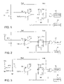
- FIG. 1 is a schematic diagram illustrating a first circuit for measuring resistance
- FIG. 2 is a schematic diagram illustrating a second circuit for measuring resistance
- FIG. 3 is a schematic diagram illustrating a third circuit for measuring resistance.
- FIG. 1 illustrates a first embodiment of the invention comprising a comparator U 1 and a D flip-flop U 2 .
- a clock signal CLK having a fixed pulse repetition rate latches the output of the comparator into the flip-flop.
- the /Q output of the flip-flop is connected to the non-inverting input of the comparator through a resistor Rref.
- a thermistor RT 1 and a capacitor C are connected in parallel between the non-inverting input of the comparator and the negative rail (ground).
- the resistor Rref, thermistor RT 1 and capacitor C form an integrator connected between the /Q output of the flip-flop and the non-inverting input of the comparator.
- the inverting input of the comparator is connected to a fixed threshold voltage Vref.
- the integrator and the comparator form a sigma-delta converter.
- the clock pulses are counted (COUNT A) by a counter 10 .
- the clock signal CLK is also applied to one input of an AND gate, whose other input is connected to the Q output of the flip-flop U 2 .
- the clock pulses are blocked by the AND gate, but when the Q output of the flip-flop is high, the clock pulses are passed by the AND gate and are counted (COUNT B) by a counter 12 .
- the number of pulses counted by the counter 12 in a fixed interval divided by the number of pulses counted by the counter 10 in the same interval is the proportion of time for which the output signal of the comparator is in the logic true state and is referred to herein as the measurement ratio.
- the comparator If the voltage Vin at the non-inverting input of the comparator is greater than the threshold voltage Vref, the comparator provides a logic true output, which is latched into the flip-flop.
- the Q output of the flip-flop goes high and the counter 12 starts counting the clock pulses.
- the /Q output of the flip-flop goes low and the capacitor C discharges, and the voltage Vin falls, until the voltage Vin is lower than the threshold voltage.
- the comparator then provides a logic false output which is latched into the flip-flop by the next clock pulse.
- the Q output of the flip-flop goes low and the counter 12 stops counting the clock pulses.
- the /Q output of the flip-flop goes high and the capacitor C charges, and the voltage Vin rises, until the voltage Vin is higher than the threshold voltage and the comparator again provides a logic true output. If the resistance of the thermistor is constant, after several repetitions of this sequence a steady state is attained in which the voltage Vin is equal to Vref.
- V in V out*( RT 1/( R ref+ RT 1)) and the mean value of Vout over an integer number of repetitions of the above sequence is equal to Vcc*Nlo, where Nlo is the measurement ratio for the circuit configuration shown in FIG. 1 .
- Vref Vcc* N lo*( RT 1/(Rref+ RT 1))
- RT 1 Vref*Rref/(Vcc* N lo ⁇ Vref)
- FIG. 2 illustrates a second embodiment of the invention, in which the thermistor RT 1 is connected to Vcc.
- the mode of operation is similar to that of the FIG. 1 embodiment, and in this case we denote the measurement ratio as Nhi.
- Vin ((Vcc ⁇ Vout)*(Rref/(Rref+ RT 1)))+Vout and the mean value of Vout over an integer number of repetitions of the above sequence is equal to Vcc*Nhi.
- Vref ((Vcc ⁇ Vcc* N hi)*(Rref/(Rref+ RT 1)))+Vcc* N hi
- RT 1 Rref(Vcc ⁇ Vref)/(Vref ⁇ Vcc* N hi)
- FIGS. 1 and 2 may be implemented in a commercially available microcontroller using firmware that is appropriately programmed to perform the necessary functions.
- a preferred microcontroller is a microcontroller of the MSP430x11x1 series from Texas Instruments, since the microcontrollers of that series include a comparator.
- the circuits shown in FIGS. 1 and 2 are subject to a number of potential measurement errors.
- any error in the fixed threshold voltage Vref supplied to the comparator will result in measurement error.
- One potential source of error in the threshold voltage Vref is caused by changes in the supply voltage and the associated positive rail voltage Vcc.
- a second potential error is the common mode offset voltage in the comparator. It is known that this error may be eliminated by switching the inputs and the output polarity of the comparator half-way through the measurement. Thus, both the circuit shown in FIG. 1 and that shown in FIG. 2 may be compensated for common mode offset voltage by making each measurement in two halves. In the first half the measurement ratio Nlo or Nhi is measured with the comparator connected as shown and in the second half the inputs to the comparator are reversed and the output of the comparator is inverted. By taking the mean of the two values of Nlo or Nhi the measurement ratio is corrected for common mode offset error.
- a third potential error in the threshold voltage Vref is the variation in the threshold voltage Vref from device to device.
- Other devices using the ⁇ - ⁇ ADC use calibration as a means to eliminate this error.
- the error is eliminated by switching between the two functional configurations shown in FIGS. 1 and 2 respectively.
- a switch SW 1 is first set to configure the microcontroller to function as shown in FIG. 1 , and the ratio Nlo is measured.
- the switch SW 1 is then set to tie the thermistor to the positive rail, as shown in FIG. 2 , and the ratio Nhi is measured.
- Each measurement includes switching of the comparator inputs and output polarity to compensate for common mode offset error, as described above.
- the threshold voltage Vref and positive rail Vcc shift as a fixed ratio with the supply voltage and so even if the supply voltage changes suddenly, the ratio of Vref to Vcc, i.e. x, is not affected by the change.
- a complete measurement involves four full cycles. There are two measurements of Nlo (thermistor connected to ground), first with the comparator output polarity positive, circuit node 14 connected to the non-inverting input and Vref connected to the inverting input, as shown, and then with the comparator output polarity negative, the circuit node 14 connected to the inverting input and Vref connected to the non-inverting input.
- Nlo thermoistor connected to ground
- Nhi thermoistor connected to VCC
- the input pin connected to the capacitor is programmed as an output pin and pulled low, allowing the capacitor to discharge. This forces all measurement cycles to begin from the same starting point, 0 VDC.
- the thermal function is uniquely related to the temperature via the Steinhart-Hart equation:
- I T a + bln ⁇ ( R ) + c ⁇ [ ln ⁇ ( R ) ] 3 whose coefficients a, b, and c are constants and characteristic of the material used to manufacture the thermistor.
- a medical-grade thermistor is used which has a high degree of repeatability from part to part, and whose resistance-to-temperature relationship is very accurately known and provided by the supplier of the thermistor.
- the resistance is scaled by the reference resistor (Rref) and entered in a lookup table in 1 degree Celsius steps.
- a table search finds the integer part of the temperature and linear interpolation between table points finds the fractional portion of the measurement.
- thermometer is able to measure temperature over a 25° C. range, from +25° C. to +50° C., with an accuracy of +/ ⁇ 0.1° C.
- the resistive element (thermistor) and the microcontroller form a miniature, low-cost, battery-operated thermometer that requires no calibration and is useful for ambulatory human or animal temperature measurement.
- the temperature-sensitive resistive element By incorporating the temperature-sensitive resistive element into the ⁇ - ⁇ ADC and implementing the remaining functions in a microcontroller, a minimum number of parts and power is used while maintaining a very high degree of conversion accuracy.
- thermometer can be made small enough to fit into an ingestible pill for measuring body core temperature, in a small skin patch for measuring skin temperature, in a capsule that can be placed in a body orifice, such as the ear canal, or implanted elsewhere in a human or animal subject, or in the form of a small transmitter for use in measuring ambient temperature.
Abstract
Description
determines the frequency of oscillation, where R is the resistance of the resistive element (thermistor) and C is the capacitance of the series charging capacitor. As the temperature varies, the resistance of the thermistor varies, and the frequency varies as a result. By measuring the frequency, and knowing the value of the capacitance, the value of R can be determined. Because R is uniquely related to temperature, the temperature can be determined as well. For a thermistor, the resistance is related to the temperature via the Steinhart-Hart equation. The use of a multivibrator as the oscillator circuit is disclosed in U.S. Pat. No. 4,359,285 by Washburn for low-power oceanographic applications. U.S. Pat. Nos. 4,602,871 and 4,464,067 issued to Hanaoka disclose thermometers based on thermistor-controlled oscillators whose properties emphasize miniaturization, light weight, and improved accuracy using correcting circuits. These latter two patents refer to applications wherein the sensor may be used with low-power wristwatch devices.
Vin=Vout*(RT1/(Rref+RT1))
and the mean value of Vout over an integer number of repetitions of the above sequence is equal to Vcc*Nlo, where Nlo is the measurement ratio for the circuit configuration shown in
Vref=Vcc*Nlo*(RT1/(Rref+RT1))
Solving for RT1:
RT1=Vref*Rref/(Vcc*Nlo−Vref)
Vin=((Vcc−Vout)*(Rref/(Rref+RT1)))+Vout
and the mean value of Vout over an integer number of repetitions of the above sequence is equal to Vcc*Nhi. Substituting for Vin and Vout:
Vref=((Vcc−Vcc*Nhi)*(Rref/(Rref+RT1)))+Vcc*Nhi
RT1=Rref(Vcc−Vref)/(Vref−Vcc*Nhi)
x=Nlo*(RT1/(Rref+RT1))
and in the case of the
x=((1−Nhi)*(Rref/(Rref+RT1)))+Nhi
Nlo*(RT1/(Rref+RT1))=((1−Nhi)*(Rref/(Rref+RT1)))+Nhi
RT1*Nlo=(Rref*(1−Nhi))+((Rref+RT1)*Nhi)
RT1=Rref/(Nlo−Nhi)
whose coefficients a, b, and c are constants and characteristic of the material used to manufacture the thermistor. For highest accuracy, a medical-grade thermistor is used which has a high degree of repeatability from part to part, and whose resistance-to-temperature relationship is very accurately known and provided by the supplier of the thermistor.
Claims (14)
Priority Applications (5)
| Application Number | Priority Date | Filing Date | Title |
|---|---|---|---|
| US11/391,944 US7250777B2 (en) | 2005-03-30 | 2006-03-28 | Method and device for measuring resistance |
| EP06749060.7A EP1872143B1 (en) | 2005-03-30 | 2006-03-29 | Method and device for measuring resistance |
| CA2614588A CA2614588C (en) | 2005-03-30 | 2006-03-29 | Method and device for measuring resistance |
| AU2006230496A AU2006230496B2 (en) | 2005-03-30 | 2006-03-29 | Method and device for measuring resistance |
| PCT/US2006/012004 WO2006105421A2 (en) | 2005-03-30 | 2006-03-29 | Method and device for measuring resistance |
Applications Claiming Priority (2)
| Application Number | Priority Date | Filing Date | Title |
|---|---|---|---|
| US66684705P | 2005-03-30 | 2005-03-30 | |
| US11/391,944 US7250777B2 (en) | 2005-03-30 | 2006-03-28 | Method and device for measuring resistance |
Publications (2)
| Publication Number | Publication Date |
|---|---|
| US20060250145A1 US20060250145A1 (en) | 2006-11-09 |
| US7250777B2 true US7250777B2 (en) | 2007-07-31 |
Family
ID=37054180
Family Applications (1)
| Application Number | Title | Priority Date | Filing Date |
|---|---|---|---|
| US11/391,944 Active US7250777B2 (en) | 2005-03-30 | 2006-03-28 | Method and device for measuring resistance |
Country Status (5)
| Country | Link |
|---|---|
| US (1) | US7250777B2 (en) |
| EP (1) | EP1872143B1 (en) |
| AU (1) | AU2006230496B2 (en) |
| CA (1) | CA2614588C (en) |
| WO (1) | WO2006105421A2 (en) |
Cited By (1)
| Publication number | Priority date | Publication date | Assignee | Title |
|---|---|---|---|---|
| US20160053737A1 (en) * | 2014-08-21 | 2016-02-25 | Kold Ban International, Ltd. | Plc controlled supplemental starting system |
Families Citing this family (6)
| Publication number | Priority date | Publication date | Assignee | Title |
|---|---|---|---|---|
| US8092084B2 (en) * | 2008-07-28 | 2012-01-10 | Finesse Solutions, Llc | System and method for temperature measurement |
| US10122478B2 (en) * | 2015-02-27 | 2018-11-06 | Purdue Research Foundation | Methods and devices for real-time monitoring of tunable filters |
| ITUB20160548A1 (en) | 2016-02-08 | 2017-08-08 | St Microelectronics Srl | RESISTIVE SENSOR INTERFACE |
| US11153935B2 (en) * | 2017-06-15 | 2021-10-19 | Goodrich Corporation | Latching thermostats for redundant heating |
| WO2019219842A1 (en) * | 2018-05-17 | 2019-11-21 | Ams International Ag | Sensor arrangement and method for sensor measurement |
| CN113203502A (en) * | 2021-04-19 | 2021-08-03 | 杭州电子科技大学 | High-precision temperature detection device suitable for mass production and mass production method thereof |
Citations (12)
| Publication number | Priority date | Publication date | Assignee | Title |
|---|---|---|---|---|
| US3875503A (en) * | 1972-11-15 | 1975-04-01 | Yokogawa Electric Works Ltd | Dual slope type resistance deviation measuring apparatus |
| US4117722A (en) * | 1977-11-14 | 1978-10-03 | Honeywell Inc. | Measuring apparatus providing separate analog and digital outputs |
| US4150573A (en) | 1976-12-03 | 1979-04-24 | Tokyo Shibaura Electric Co., Ltd. | Electronic digital thermometer |
| US4464067A (en) | 1982-01-22 | 1984-08-07 | Citizen Watch Company Limited | Thermistor frequency controlled electronic thermometer |
| US4598270A (en) * | 1984-10-04 | 1986-07-01 | Rockwell International Corporation | Precision integrating analog-to-digital converter system |
| US4602871A (en) | 1984-10-23 | 1986-07-29 | Citizen Watch Co., Ltd. | Thermistor thermometer |
| US4689621A (en) | 1986-03-31 | 1987-08-25 | The United States Of America As Represented By The Administrator Of The National Aeronautics And Space Administration | Temperature responsive transmitter |
| US4814692A (en) * | 1984-09-06 | 1989-03-21 | Mettler Instrument Ag | Circuit and method for measuring and digitizing the value of a resistance |
| US4844076A (en) | 1988-08-26 | 1989-07-04 | The Johns Hopkins University | Ingestible size continuously transmitting temperature monitoring pill |
| US5886586A (en) * | 1996-09-06 | 1999-03-23 | The Regents Of The University Of California | General constant frequency pulse-width modulators |
| US6629776B2 (en) | 2000-12-12 | 2003-10-07 | Mini-Mitter Company, Inc. | Digital sensor for miniature medical thermometer, and body temperature monitor |
| US6930495B1 (en) * | 2003-04-25 | 2005-08-16 | National Semiconductor Corporation | Digitizing ohmmeter system |
Family Cites Families (1)
| Publication number | Priority date | Publication date | Assignee | Title |
|---|---|---|---|---|
| US4161880A (en) * | 1978-01-05 | 1979-07-24 | Electromedics, Inc. | Linearized digital thermometer |
-
2006
- 2006-03-28 US US11/391,944 patent/US7250777B2/en active Active
- 2006-03-29 EP EP06749060.7A patent/EP1872143B1/en active Active
- 2006-03-29 AU AU2006230496A patent/AU2006230496B2/en active Active
- 2006-03-29 WO PCT/US2006/012004 patent/WO2006105421A2/en active Application Filing
- 2006-03-29 CA CA2614588A patent/CA2614588C/en active Active
Patent Citations (12)
| Publication number | Priority date | Publication date | Assignee | Title |
|---|---|---|---|---|
| US3875503A (en) * | 1972-11-15 | 1975-04-01 | Yokogawa Electric Works Ltd | Dual slope type resistance deviation measuring apparatus |
| US4150573A (en) | 1976-12-03 | 1979-04-24 | Tokyo Shibaura Electric Co., Ltd. | Electronic digital thermometer |
| US4117722A (en) * | 1977-11-14 | 1978-10-03 | Honeywell Inc. | Measuring apparatus providing separate analog and digital outputs |
| US4464067A (en) | 1982-01-22 | 1984-08-07 | Citizen Watch Company Limited | Thermistor frequency controlled electronic thermometer |
| US4814692A (en) * | 1984-09-06 | 1989-03-21 | Mettler Instrument Ag | Circuit and method for measuring and digitizing the value of a resistance |
| US4598270A (en) * | 1984-10-04 | 1986-07-01 | Rockwell International Corporation | Precision integrating analog-to-digital converter system |
| US4602871A (en) | 1984-10-23 | 1986-07-29 | Citizen Watch Co., Ltd. | Thermistor thermometer |
| US4689621A (en) | 1986-03-31 | 1987-08-25 | The United States Of America As Represented By The Administrator Of The National Aeronautics And Space Administration | Temperature responsive transmitter |
| US4844076A (en) | 1988-08-26 | 1989-07-04 | The Johns Hopkins University | Ingestible size continuously transmitting temperature monitoring pill |
| US5886586A (en) * | 1996-09-06 | 1999-03-23 | The Regents Of The University Of California | General constant frequency pulse-width modulators |
| US6629776B2 (en) | 2000-12-12 | 2003-10-07 | Mini-Mitter Company, Inc. | Digital sensor for miniature medical thermometer, and body temperature monitor |
| US6930495B1 (en) * | 2003-04-25 | 2005-08-16 | National Semiconductor Corporation | Digitizing ohmmeter system |
Cited By (1)
| Publication number | Priority date | Publication date | Assignee | Title |
|---|---|---|---|---|
| US20160053737A1 (en) * | 2014-08-21 | 2016-02-25 | Kold Ban International, Ltd. | Plc controlled supplemental starting system |
Also Published As
| Publication number | Publication date |
|---|---|
| WO2006105421A2 (en) | 2006-10-05 |
| CA2614588C (en) | 2015-03-24 |
| US20060250145A1 (en) | 2006-11-09 |
| CA2614588A1 (en) | 2006-10-05 |
| WO2006105421A3 (en) | 2007-04-12 |
| EP1872143A2 (en) | 2008-01-02 |
| AU2006230496B2 (en) | 2010-10-21 |
| EP1872143B1 (en) | 2018-09-12 |
| AU2006230496A1 (en) | 2006-10-05 |
| EP1872143A4 (en) | 2015-12-02 |
Similar Documents
| Publication | Publication Date | Title |
|---|---|---|
| US7250777B2 (en) | Method and device for measuring resistance | |
| EP1342060B1 (en) | Digital sensor for miniature medical thermometer, and body temperature monitor | |
| US4150573A (en) | Electronic digital thermometer | |
| ES2333734T3 (en) | DEVICE FOR ANALOG / DIGITAL CONVERSION OF A MEASURED VOLTAGE. | |
| CA1114635A (en) | Temperature measurement apparatus | |
| US7589538B2 (en) | Micropower voltage-independent capacitance measuring method and circuit | |
| EP1279964B1 (en) | Resistance measuring circuit | |
| KR20140056155A (en) | Semiconductor temperature sensors | |
| KR20140094601A (en) | High resolution temperature measurement | |
| US11448609B2 (en) | Method for operating a gas sensor arrangement and gas sensor arrangement | |
| EP0434030A1 (en) | Pressure detector by use of quartz oscillator | |
| JPS5833490B2 (en) | temperature measuring device | |
| RU2502076C1 (en) | Microcontroller metering converter of resistance into binary code with voltage-controlled generator | |
| US4132116A (en) | Method for linearizing the characteristic curve of an electronic component and an apparatus for implementing the same | |
| CN109724711B (en) | Temperature sensor and temperature sensing method | |
| TWI505810B (en) | Voltage-frequency conversion circuit and blood pressure measuring device | |
| RU105477U1 (en) | DEVICE FOR MEASURING METEOROLOGICAL VALUES AND FORMING AEROLOGICAL RADIO PROBE TELEMETRY SIGNAL | |
| RU2017087C1 (en) | Temperature gauge with frequency output | |
| JPS5895230A (en) | Method and apparatus for electronic type temperature measurement | |
| GB1584294A (en) | Method and apparatus for measuring using an electrical component having an exponential characteristic curve | |
| RU53462U1 (en) | MEASURING TRANSMITTER OF AEROLOGICAL RADIO PROBE | |
| RU2653092C1 (en) | Multichannel device for bulk solids moisture measurement | |
| JP3359042B2 (en) | A method for measuring time intervals with high resolution | |
| US7091725B2 (en) | Fast, high-resolution, indirect measurement of a physical value | |
| RU2631018C2 (en) | Multi-channel temperature control device |
Legal Events
| Date | Code | Title | Description |
|---|---|---|---|
| AS | Assignment |
Owner name: MINI-MITTER COMPANY, INC., OREGON Free format text: ASSIGNMENT OF ASSIGNORS INTEREST;ASSIGNORS:KOBBE, RICK ALLEN;BELL, FLORIAN G.;BARTON, DONNA K.;REEL/FRAME:017684/0262 Effective date: 20060523 |
|
| STCF | Information on status: patent grant |
Free format text: PATENTED CASE |
|
| FPAY | Fee payment |
Year of fee payment: 4 |
|
| FPAY | Fee payment |
Year of fee payment: 8 |
|
| MAFP | Maintenance fee payment |
Free format text: PAYMENT OF MAINTENANCE FEE, 12TH YEAR, LARGE ENTITY (ORIGINAL EVENT CODE: M1553); ENTITY STATUS OF PATENT OWNER: LARGE ENTITY Year of fee payment: 12 |