EP0180221B1 - Einschnappgelenk mit geraden Bändern in verschlossenem Zustand - Google Patents
Einschnappgelenk mit geraden Bändern in verschlossenem Zustand Download PDFInfo
- Publication number
- EP0180221B1 EP0180221B1 EP85113866A EP85113866A EP0180221B1 EP 0180221 B1 EP0180221 B1 EP 0180221B1 EP 85113866 A EP85113866 A EP 85113866A EP 85113866 A EP85113866 A EP 85113866A EP 0180221 B1 EP0180221 B1 EP 0180221B1
- Authority
- EP
- European Patent Office
- Prior art keywords
- cover
- closure
- main hinge
- hinge
- connecting element
- Prior art date
- Legal status (The legal status is an assumption and is not a legal conclusion. Google has not performed a legal analysis and makes no representation as to the accuracy of the status listed.)
- Expired - Lifetime
Links
Images

Classifications
-
- B—PERFORMING OPERATIONS; TRANSPORTING
- B65—CONVEYING; PACKING; STORING; HANDLING THIN OR FILAMENTARY MATERIAL
- B65D—CONTAINERS FOR STORAGE OR TRANSPORT OF ARTICLES OR MATERIALS, e.g. BAGS, BARRELS, BOTTLES, BOXES, CANS, CARTONS, CRATES, DRUMS, JARS, TANKS, HOPPERS, FORWARDING CONTAINERS; ACCESSORIES, CLOSURES, OR FITTINGS THEREFOR; PACKAGING ELEMENTS; PACKAGES
- B65D41/00—Caps, e.g. crown caps or crown seals, i.e. members having parts arranged for engagement with the external periphery of a neck or wall defining a pouring opening or discharge aperture; Protective cap-like covers for closure members, e.g. decorative covers of metal foil or paper
- B65D41/62—Secondary protective cap-like outer covers for closure members
-
- B—PERFORMING OPERATIONS; TRANSPORTING
- B65—CONVEYING; PACKING; STORING; HANDLING THIN OR FILAMENTARY MATERIAL
- B65D—CONTAINERS FOR STORAGE OR TRANSPORT OF ARTICLES OR MATERIALS, e.g. BAGS, BARRELS, BOTTLES, BOXES, CANS, CARTONS, CRATES, DRUMS, JARS, TANKS, HOPPERS, FORWARDING CONTAINERS; ACCESSORIES, CLOSURES, OR FITTINGS THEREFOR; PACKAGING ELEMENTS; PACKAGES
- B65D47/00—Closures with filling and discharging, or with discharging, devices
- B65D47/04—Closures with discharging devices other than pumps
- B65D47/06—Closures with discharging devices other than pumps with pouring spouts or tubes; with discharge nozzles or passages
- B65D47/08—Closures with discharging devices other than pumps with pouring spouts or tubes; with discharge nozzles or passages having articulated or hinged closures
- B65D47/0804—Closures with discharging devices other than pumps with pouring spouts or tubes; with discharge nozzles or passages having articulated or hinged closures integrally formed with the base element provided with the spout or discharge passage
- B65D47/0809—Closures with discharging devices other than pumps with pouring spouts or tubes; with discharge nozzles or passages having articulated or hinged closures integrally formed with the base element provided with the spout or discharge passage and elastically biased towards both the open and the closed positions
- B65D47/0814—Closures with discharging devices other than pumps with pouring spouts or tubes; with discharge nozzles or passages having articulated or hinged closures integrally formed with the base element provided with the spout or discharge passage and elastically biased towards both the open and the closed positions by at least three hinge sections, at least one having a length different from the others
Definitions
- This invention relates to a resilient snap-action closure for a container wherein said closure includes:
- each said connecting element being joined to said body with a first hinge and to said cover with a second hinge so as to locate said connecting elements offset in a first position relative to the main hinge axis when the cover is in the said open position whereby said cover is held open, the closure deforming elastically as the cover is moved from said open position to said closed position about said main hinge axis until said closure snaps through a dead center position at which said closure is maximally deformed, said connecting elements being located in a second position relative to the main hinge axis when the cover is in said closed position where the deformation is at least partly reduced so that said cover is urged to said closed position.
- a resilient snap-action closure of the aforementioned type is known from US-A-3 741 447.
- the connecting elements of this known closure always have a generally semi-circular configuration in both the open and closed position of the closure cover. Further, they project out from the closure, when the cover is closed.
- an improved closure should advantageously have a configuration in the closed position that is substantially free of projections or features that might interfere with some types of conventional automatic capping machines.
- a closure having substantially no interfering exterior projections should also have a configuration with a relatively large interior usable space. That is, it would be advantageous if the structures employed to effect the snap-action of the improved closure did not project too far inwardly so as to interfere with potential use of the interior region of the closure.
- each said connecting element has a generally linear configuration adjacent said cover and body when said cover is in said closed position and has a non-linear configuration lying generally in a plane parallel to said main hinge axis and said cover is in said open position.
- the closure includes two spaced-apart connecting elements that are each joined to the body with a first hinge and to the cover with a second hinge so as to locate the connecting elements offset on one side of the main hinge axis when the cover is in the open position whereby the cover is held open.
- the closure deforms elastically as the cover is moved from the open position to the closed position about the main hinge axis until the closure snaps through a dead center position at which the closure is maximally deformed and beyond which both of the connecting elements are located on the other side of the main hinge axis where the deformation is at least partly reduced so that the cover is urged to the closed position.
- Each connecting element has a generally linear configuration adjacent the cover and body when the cover is in the closed position.
- Each connecting element has a non-linear configuration lying generally in a plane parallel to the main hinge axis when the cover is in the open position.
- closure of this invention is described in use on a container, or as part of a container, with the container being oriented in a normal (upright) position. Terms such as upper, lower, horizontal, etc., are used with reference to this position. It will be understood, however, that the closure of this invention may be manufactured, stored, transported, used, and sold in an orientation other than the position described.
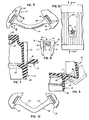
- FIG. 1 A first embodiment ofthe closure of the present invention is illustrated in Figure 1 wherein the closure is represented generally by the reference numeral 12.
- the closure 12 is shown in Figure 1 as being mounted on a container 14.
- the closure 12 includes a collar, base, or body 16 for being joined to the container 14, either in a unitary manner or by other removable or non-removable means (e.g., threading engagement, snap-on engagement, bonding by means of adhesive or welding, etc.).
- the closure 12 includes a cover, cap, or lid 18 adapted to be disposed upon the body 16.
- the cover 18 is shown on top of the body 16 in a closed position in Figure 1 and in an open position in Figure 2.
- the interior structure of the closure 12 illustrated in Figure 2 may vary depending upon the type of container 14, upon the type of contents to be dispensed from the container 14, and upon the dispensing action that is desired.
- One specific interior configuration is shown in the Figures for illustrative purposes only.
- the closure body 16 has a generally flat closure end portion or cross wall 20 with a generally cylindrical discharge spout 22 defining an opening 24 for dispensing the contents of the container 14.
- the body 16 includes a skirt 26 which defines at least a partially cylindrical portion of the closure 12. In the illustrated first embodiment, the skirt 26 is generally cylindrical but includes an undercut, angled thumb-notch surface 28.
- the cover 18 is movable between the closed position on the container 14 (as shown in Figure 1) for engaging the body 16 to close off the body opening 24 and the opening position (as shown in Figure 2) spaced from the body opening 24.
- the cover 18 defines at least a partially cylindrical portion or skirt 30.
- the skirt 30 is generally cylindrical with an outwardly projecting thumb tab 32 which overlies the body thumb-notch 28 when the cover 18 is in the closed position.
- the cover 18 also includes an end cross-wall 34 at the upper end of the cylindrical skirt 30.
- a spud 36 which is a hollow, generally cylindrical member for entering into the opening 24 in the spout 22 of the body 16.
- the spud 36 preferably has a frustoconical surface 38 for guiding the spud 36 into the spout 22.
- the cover 18 close in general registry on top of the body 16.
- the body 16 defines an annular shoulder 40 below the body cross wall 20.
- the bottom edge of the cover skirt 30 is received on the shoulder 40 with the body cross wall 20 projecting upwardly within the skirt 30.
- the closure body 16 is adapted to be threaded onto the neck of the container 14.
- the interior of the body cylindrical skirt 26 is provided with conventional threads 44.
- the threads 44 are adapted to engage suitable mating threads on the neck of the container 14.
- the underside of the body cross wall 20 of the body 16 may be provided with a annular seal 45 ( Figure 4) for sealing against the top of the container 14 when full threading engagement has been achieved.
- the cover 18 is hinged to the body 16 for pivoting movement about a main hinge axis defined by a main hinge 50.
- the main hinge 50 is a member having a first portion 51 joined to the body 16 and having a second portion 52 joined to the cover 18.
- the main hinge first portion 51 is larger than the main hinged second portion 52 and is joined to the main hinge second portion 52 in a unitary structure with a film hinge 53.
- the main hinge first portion 51 slopes outwardly from the body 16 to the film hinge 53.
- the main hinge second portion 52 slopes outwardly from the cover 18 to the film hinge 53.
- the length of the slope of the main hinge first portion 51 is greater than the length of the slope of the main hinge second portion 52.
- the structure of the main hinge 50 can be further defined with reference to its shape in such an "as molded" full open position.
- the film hinge 53 of the main hinge 50 defines a recessed, generally planar surface 54 on the exposed interior region of the closure 12.
- the film hinge 53 is defined in part by a first partially cylindrical surface 56 which merges with the main hinge first portion 51.
- the film hinge 53 is defined in part on the exterior region of the closure by a second partially cylindrical surface 58 which merges with the main hinge second portion 52 and with the first partially cylindrical surface 56.
- the radius of curvature of the first partially cylindrical surface 56 is less than the radius of curvature of the second partially cylindrical surface 58.
- the first partially cylindrical surface 56 defines an arc which subtends an angle A as illustrated in Figure 8.
- the second partially cylindrical surface 58 defines an arc which subtends an angle B as illustrated in Figure 8.
- the radius of curvature of the arc defined by the first partially cylindrical surface 56 is about 0.02
- the radius of curvature of the second partially cylindrical surface 58 is about 0.03
- the length of the recessed planar surface 54 is about 0.06".
- the planar surface 54 is recessed to a depth of about 0.005".
- the thickness of the film hinge 53 measured through a plane perpendicular to, and bisecting, the surface 54 is about 0.015" with the surfaces of the hinge first portion 51 and hinge second portion 52 each being oriented at an angle of about 15° relative to the bisecting plane.
- a pair of spaced-apart, somewhat stiff straps or connecting elements 70 are provided on opposite ends of the main hinge 50.
- Each connecting element 70 is connected to the cylindrical skirt 26 of the body 16 with a first hinge 71 and to the cylindrical skirt 30 of the cover 18 with a second hinge 72.
- the closure of the present invention may be molded from a thermoplastic material, and each connecting element hinge 71 and 72, as well as the main hinge 50, may be a "living" film hinge.
- each connecting element 70 has generally circular transverse cross-section.
- Each element 70 has a first end portion 81 ( Figure 5) at the first hinge 71 that is generally perpendicular to the axis of the first hinge 71.
- each connecting element 70 has a second end portion 82 ( Figure 5) that is generally perpendicular to the axis of the second hinge 72.
- the end portions 81 and 82 each flare outwardly to a width that is greater than twice the diameter of the circular transverse cross-section of the connecting element 70.
- Each connecting element 70 has a generally elongate configuration. When the closure cover 18 is in the open position, each connecting element 70 has a non-linear configuration, such as the generally curved configuration illustrated in Figures 3 and 5, which lies generally in a plane parallel to the main hinge axis.
- the closure 12 is molded from polypropylene with the cover 18 in a full open position (as illustrated in Figures 3 and 4) with each connecting element 70 being formed in an arcuate, elongate configuration.
- the molding is effected to produce an orientation of the macromolecular chains of polypropylene along the length of each connecting element 70. This provides a relatively strong structure with respect to withstanding forces that are applied to the ends of the connecting elements 70 in directions generally perpendicular to the connecting element hinges 71 and 72.
- each connecting element 70 In a specific size closure made in accordance with the teachings of the present invention, the diameter of the circular transverse cross-section of each connecting element 70 is about 0.038", and each connecting element 70 maintains a generally circular arc configuration when the cover is in the open position.
- the inner arc radius of each element 70 is about 0.216".
- Such a closure may be molded in the open position with the center of the connecting element circular arc lying in a first plane that 1) contains the axis of the main hinge 50 and 2) is generally perpendicular to a second plane containing both connecting elements 70 in the molded full open position ( Figures 3 and 4).
- each connecting element 70 is adapted to be received within the cylindrical skirt portions of the closure body 16 and closure cover 18. This is best illustrated in Figures 1, 2, and 5-7.
- the body 16 defines two spaced-apart channels 90 at opposite ends of the main hinge 50.
- the cover 18 defines two spaced-apart channels 92 at opposite ends of the main hinge 50.
- On each end of the main hinge 50 one of the cover channels 92 and one of the body channels 90 are in end-to-end registry when the cover 18 is in the closed position so as to define a recess for receiving one of the connecting elements 70.
- the closure 12 is elastically deformable as the cover 18 is moved from the open position to the closed position about the axis of the main hinge 50.
- the cylindrical skirt 30 of the cover 18 is elastically deformable or resilient, at least in the region adjacent the main hinge 50. Specifically, with reference to Figure 9, it can be seen that as the cover 18 moves from the open position (illustrated in dashed lines) toward the closed position, the cylindrical skirt 30 near the hinge 50 bends inwardly somewhat.
- connecting elements 70 are offset on one side of the axis of the main hinge 50 when the cover 18 is in the open position (as shown in dashed lines) and become located on the other side of the axis of the main hinge 50 as the closure snaps through the dead center position.
- FIG. 9 illustrate the approximate dead center positoin of the closure 12 wherein the closure cover 18 is maximally deformed.
- the deformation of the cylindrical skirt 30 of the cover 18 can be seen in Figure 9 as an inward bending of the skirt 30 through an angle C relative to a line generally perpendicular to the plane defining the bottom edge of the skirt 30.
- the connecting elements 70 begin to straighten out from the non-linear configuration to a substantially straight or linear configuration.
- the connecting elements 70 remain substantially straight and ultimately lie adjacent the body 16 and cover 18 when the closure is fully closed.
- the recesses 90 in the body 16 and the recesses 92 in the cover 18 function to receive the straightened connecting elements 70.
- the connecting elements 70 do not project beyond the exterior surface of the closure in the closed position.
- the connecting elements 70 may be characterized as having a generally linear configuration adjacent the body 16 and closed cover 18.
- closure 12 of the present invention When a closure 12 of the present invention is fabricated by molding a thermoplastic material, the closure 12 may preferably be molded in a completely open position as illustrated in Figures 3 and 4. In this open position the cover 18 is disposed at a substantially 180° angle relative the body 16 as measured about a vertex defined the main hinge axis.
- the cover 18 With typical thermoplastic materials used for the closure fabrication, such as polypropylene, the cover 18 initially maintains the fully opened position illustrated in Figure 4 after the closure is removed from the mold. However, after the cover 18 is closed once or twice the cover 18 will not thereafter assume the fully opened position illustrated in Figure 4. Typically, some degree of permanent deformation occurs in the closure structure when it is first closed, and the cover 18 will then typically reopen to an orientation somewhat less than 180° from the body 16. Such a "reopen” or "normal open” orientation is illustrated in Figure 2. Clearly, the cover 18 is still pivoted a sufficient amount relative to the body 16 to provide the desired access to the body opening 24.
- both connecting elements 70 when the cover 18 is in the open position (either the molded full open position illustrated in Figure 4 or the reopen position illustrated in Figure 2), both connecting elements 70 have a non-linear configuration lying generally in a common plane parallel to the axis of the main hinge 50.
- the connecting elements 70 are sufficiently rigid so as to maintain the generally non-linear configuration when the cover 18 is in the self-maintained open position.
- each connecting element 70 it is not necessary that each connecting element 70 have an arcuate configuration in the open position. Non-arcuate configurations may be provided as will next be explained.
- Figure 10 shows an alternate embodiment in which a connecting element 70' is provided between a body 16' and a cover 18'.
- the connecting element 70' has an angled configuration when the closure is in the open position. Specifically, the connecting element 70' has a first straight portion 101 adjacent the body 16' and a second straight portion 102 adjacent the cover 18'.
- the second straight portion 102 is oriented at an angle relative to the first straight portion 101 when the closure is in the open orientation.
- the connecting element 70' straightens out into a generally linear configuration adjacent the closed body and cover.
- the novel non-linear open configuration of the connecting elements 70 (70') provides for an improved snap-action operation. It is also believed that the non-linear configurations of each connecting element in the open position reduces, or at least makes more uniform, the stresses at the film hinge at each end of each connecting element.
- a closure of the present invention When a closure of the present invention is molded from polypropylene, it has been found to have a relatively high snap-action operating force. Further, such a closure has been found to be relatively stable and resistant to twisting or deformation in the open position, as well as during closing of the closure. Accordingly, better closing action with improved registry results when using the closure of the present invention.
Claims (10)
dadurch gekennzeichnet, daß jedes Verbindungselement (70) eine im allgemeinen lineare Form in der Nähe des Deckels (18) und Körpers (16) aufweist, wenn der Deckel (18) sich in der Schließstellung befindet, und eine nicht lineare Gestalt aufweist, die im allgemeinen in einer Ebene liegt, welche parallel zu der Hauptscharnierachse verläuft, wenn der Deckel (18) sich in der Offenstellung befindet.
Applications Claiming Priority (2)
| Application Number | Priority Date | Filing Date | Title |
|---|---|---|---|
| US667744 | 1984-11-02 | ||
| US06/667,744 US4545495A (en) | 1984-11-02 | 1984-11-02 | Snap action hinge with closed position straight straps |
Publications (3)
| Publication Number | Publication Date |
|---|---|
| EP0180221A2 EP0180221A2 (de) | 1986-05-07 |
| EP0180221A3 EP0180221A3 (en) | 1987-11-25 |
| EP0180221B1 true EP0180221B1 (de) | 1990-05-23 |
Family
ID=24679454
Family Applications (1)
| Application Number | Title | Priority Date | Filing Date |
|---|---|---|---|
| EP85113866A Expired - Lifetime EP0180221B1 (de) | 1984-11-02 | 1985-10-31 | Einschnappgelenk mit geraden Bändern in verschlossenem Zustand |
Country Status (12)
| Country | Link |
|---|---|
| US (1) | US4545495A (de) |
| EP (1) | EP0180221B1 (de) |
| JP (1) | JPS61115849A (de) |
| KR (1) | KR860003955A (de) |
| AU (1) | AU568779B2 (de) |
| BR (1) | BR8504982A (de) |
| CA (1) | CA1237385A (de) |
| DE (1) | DE3577833D1 (de) |
| DK (1) | DK162345C (de) |
| ES (1) | ES290015Y (de) |
| MX (1) | MX162331A (de) |
| NO (1) | NO161578C (de) |
Families Citing this family (61)
| Publication number | Priority date | Publication date | Assignee | Title |
|---|---|---|---|---|
| DE3565665D1 (en) * | 1984-06-28 | 1988-11-24 | Zeller Plastik Koehn Graebner | Closure device for a container and such a container |
| US4666068A (en) * | 1984-10-25 | 1987-05-19 | Sunbeam Plastics Corporation | Two piece dispensing closure |
| DE3522597A1 (de) * | 1985-06-25 | 1987-01-08 | Benckiser Gmbh Joh A | Dosierverschluss fuer einen behaelter |
| US4638916A (en) * | 1985-07-12 | 1987-01-27 | Owens-Illinois, Inc. | Closure with snap-type hinge cap |
| US4723693A (en) * | 1986-10-02 | 1988-02-09 | Dart Industries, Inc. | Double hinging cap |
| JPS6367451U (de) * | 1986-10-21 | 1988-05-06 | ||
| US4711372A (en) * | 1987-02-02 | 1987-12-08 | Sunbeam Plastics Corporation | Tamper indicating closure |
| CH672771A5 (de) * | 1987-05-13 | 1989-12-29 | Alfatechnic Ag | |
| US4801054A (en) * | 1987-07-06 | 1989-01-31 | Owens-Illinois Closure Inc. | Watertight molded plastic dispensing closure |
| US4778071A (en) * | 1988-02-16 | 1988-10-18 | Owens-Illinois Closure Inc. | Closure with snap type hinge |
| US4793502A (en) * | 1988-02-29 | 1988-12-27 | Creative Packaging Corp. | Hinged dispensing closure |
| US4793501A (en) * | 1988-03-17 | 1988-12-27 | Creative Packaging Corp. | Water tight hinge closure |
| AU611898B2 (en) * | 1988-05-03 | 1991-06-27 | Yoshino Kogyosho Co., Ltd. | Container with elastically reversible hinge |
| US4813560A (en) * | 1988-05-04 | 1989-03-21 | Continental White Cap, Inc. | Spring hinge for dispensing cap |
| US5395015A (en) * | 1988-07-01 | 1995-03-07 | Bolen, Jr.; Robert J. | Dispensing closure with a modified lid for increased opening angle |
| US5361920A (en) * | 1989-06-16 | 1994-11-08 | Yoshino Kogyosho Co., Ltd. | Cap structure with elastic turnover cover |
| US5038957A (en) * | 1990-02-23 | 1991-08-13 | Seaquist Closures, A Division Of Pittway Corporation | Two-piece, snap-action closure with body deck spring panel |
| US5078296A (en) * | 1990-05-04 | 1992-01-07 | Kantec Manufacturing, Inc. | Container closure with stable open positions |
| US5065911A (en) * | 1990-05-14 | 1991-11-19 | Seaquist Closures | Two-piece dispensing closure with cantilevered biasing member |
| AU656281B2 (en) * | 1990-07-27 | 1995-01-27 | Yoshino Kogyosho Co., Ltd. | Cap with resiliently reversing lid |
| US5423442A (en) * | 1990-07-27 | 1995-06-13 | Yoshino Kogyosho Co., Ltd. | Cap structure with elastic turnover cover |
| US5435456A (en) * | 1991-02-12 | 1995-07-25 | Createchnic Ag | Plastic snap hinge closure |
| US5257708A (en) * | 1991-02-12 | 1993-11-02 | Createchnic Ag | Plastic snap hinge closure |
| US5148912A (en) * | 1991-02-27 | 1992-09-22 | Yoshino Kogyosho Co., Ltd. | Cap closing member for container opening |
| US5127537A (en) * | 1991-06-05 | 1992-07-07 | Graham Donald R | Tissue cassette with a living hinge |
| ATE191420T1 (de) * | 1993-05-18 | 2000-04-15 | Procter & Gamble | Flüssigkeitsbehälter |
| US5437383A (en) * | 1993-06-11 | 1995-08-01 | Stull; Gene | Snap-hinge closure cap with full circumferential seal |
| US5588546A (en) * | 1994-05-26 | 1996-12-31 | Kerr Group, Inc. | Closure with stay-open lid |
| US5489035A (en) * | 1994-10-13 | 1996-02-06 | Owens-Illinois Closure Inc. | Closure with snap-type hinge cap |
| US5913435A (en) * | 1997-04-21 | 1999-06-22 | Owens-Illinois Closure Inc. | Closure with snap-type hinge cap |
| DK1075432T3 (da) * | 1998-04-30 | 2003-02-03 | Creanova Ag | Koordineret flerakset hængsel og anvendelse heraf i et aflukkeligt emne |
| US6283298B1 (en) | 1998-11-25 | 2001-09-04 | Concept Workshop Worldwide, Llc | Airtight container and method for filling container with product |
| DE60122798T2 (de) * | 2000-01-12 | 2007-10-11 | Toyoda Gosei Co., Ltd. | Kraftstofftankfüllvorrichtung |
| US6321923B1 (en) | 2000-04-26 | 2001-11-27 | Seaquist Closures Foreign, Inc. | Bistable hinge with reduced stress regions |
| US6578744B2 (en) | 2001-03-22 | 2003-06-17 | Crown Cork & Seal Technologies Corporation | Watertight tube closure |
| US6691901B2 (en) | 2001-12-14 | 2004-02-17 | Gateway Plastics, Inc. | Closure for a container |
| US7134575B2 (en) | 2002-12-21 | 2006-11-14 | Gateway Plastics, Inc. | Closure for a container |
| US20050011906A1 (en) * | 2003-07-15 | 2005-01-20 | Kimberly-Clark Worldwide, Inc. | Storing and dispensing container for product |
| US7125457B2 (en) * | 2003-12-31 | 2006-10-24 | General Electric Company | Method for removing oxide from cracks in turbine components |
| AU2005223311A1 (en) * | 2004-03-16 | 2005-09-29 | Henkel Kommanditgesellschaft Auf Aktien | Lock provided with a film hinge |
| WO2006029092A1 (en) | 2004-09-05 | 2006-03-16 | Gateway Plastics, Inc. | Closure for a container |
| US7510095B2 (en) | 2005-03-11 | 2009-03-31 | Berry Plastics Corporation | System comprising a radially aligned container and closure |
| CN101309838B (zh) * | 2005-11-16 | 2010-12-08 | 魔法生产集团股份有限公司 | 容器和包括该容器的包装 |
| US20070289603A1 (en) * | 2006-06-15 | 2007-12-20 | Hct Asia Ltd. | Cosmetics Dispenser with Automatic Closure |
| US8113367B2 (en) * | 2007-02-20 | 2012-02-14 | Con Agra Foods RDM, Inc. | Non-removable closure having a dispensing aperture extending therethrough |
| AR067925A1 (es) * | 2008-08-13 | 2009-10-28 | Fresenius Medical Care Argentina S A | Conector para envase descartable de uso en maquinas de hemodialisis. |
| US20100193522A1 (en) * | 2009-02-05 | 2010-08-05 | Wisniewski John M | Closure with shipping latch |
| US20110062159A1 (en) * | 2009-09-11 | 2011-03-17 | Ajit Khubani | Beverage container closure with pressure release |
| USD613599S1 (en) | 2009-09-11 | 2010-04-13 | Telebrands Corp. | Beverage container closure with pressure release |
| US8448798B2 (en) * | 2010-10-05 | 2013-05-28 | Weatherchem Corporation | Dispensing closure with pliable sealing surface |
| USD738732S1 (en) | 2011-11-30 | 2015-09-15 | Tc Heartland Llc | Bottle with cap |
| USD720622S1 (en) | 2011-11-30 | 2015-01-06 | Tc Heartland Llc | Bottle with cap |
| US8899437B2 (en) | 2012-01-20 | 2014-12-02 | Gateway Plastics, Inc. | Closure with integrated dosage cup |
| USD679181S1 (en) | 2012-03-26 | 2013-04-02 | Gateway Plastics, Inc. | Closure for a container |
| US8955705B2 (en) | 2012-03-26 | 2015-02-17 | Gateway Plastics, Inc. | Closure for a container |
| US9475623B2 (en) | 2012-03-26 | 2016-10-25 | Gateway Plastics, Inc. | Closure for a container |
| WO2018064250A1 (en) * | 2016-09-28 | 2018-04-05 | The Procter & Gamble Company | Closure mechanism that prevents accidental initial opening of a container |
| US10759576B2 (en) | 2016-09-28 | 2020-09-01 | The Procter And Gamble Company | Closure interlocking mechanism that prevents accidental initial opening of a container |
| EP3489165B1 (de) | 2017-11-23 | 2022-08-17 | The Procter & Gamble Company | Verschluss für einen behälter mit einem asymmetrischen vorsprung |
| EP3489164B1 (de) | 2017-11-23 | 2023-01-25 | The Procter & Gamble Company | Verschluss für einen behälter mit drei positionen |
| USD902716S1 (en) * | 2019-05-16 | 2020-11-24 | Navajo Manufacturing Company, Inc. | Travel bottle cap having a twisting locking ring body |
Family Cites Families (11)
| Publication number | Priority date | Publication date | Assignee | Title |
|---|---|---|---|---|
| US30861A (en) * | 1860-12-11 | Improvement in corn-planters | ||
| GB521557A (en) * | 1938-11-18 | 1940-05-24 | Edgar John Foster | Improvements in or relating to hinges |
| NL128141C (de) * | 1963-03-20 | |||
| GB1056999A (en) * | 1964-12-09 | 1967-02-01 | Initial Plastics Ltd | Improvements in hinges of flexible plastics material |
| US3628215A (en) * | 1967-12-27 | 1971-12-21 | American Optical Corp | Unitary hinge and spring member |
| AT294675B (de) * | 1969-05-09 | 1971-11-25 | Unilever Nv | Behälterverschluß |
| US3752371A (en) * | 1970-07-24 | 1973-08-14 | Lion Fat Oil Co Ltd | Container cap capable of being resiliently held open and closed |
| US3741447A (en) * | 1971-11-18 | 1973-06-26 | Colgate Palmolive Co | Container cap |
| US4047495A (en) * | 1976-05-03 | 1977-09-13 | Polytop Corporation | Child resistant dispensing closures |
| CH653639A5 (de) * | 1981-01-21 | 1986-01-15 | Zeller Plastik Koehn Graebner | Einstueckiges klappscharnier aus kunststoff. |
| US4457458A (en) * | 1982-11-15 | 1984-07-03 | Knight Engineering & Molding Co. | Dispensing cap |
-
1984
- 1984-11-02 US US06/667,744 patent/US4545495A/en not_active Expired - Lifetime
-
1985
- 1985-10-08 BR BR8504982A patent/BR8504982A/pt not_active IP Right Cessation
- 1985-10-18 AU AU48852/85A patent/AU568779B2/en not_active Ceased
- 1985-10-21 MX MX343A patent/MX162331A/es unknown
- 1985-10-28 CA CA000493959A patent/CA1237385A/en not_active Expired
- 1985-10-31 ES ES1985290015U patent/ES290015Y/es not_active Expired
- 1985-10-31 EP EP85113866A patent/EP0180221B1/de not_active Expired - Lifetime
- 1985-10-31 DE DE8585113866T patent/DE3577833D1/de not_active Expired - Fee Related
- 1985-11-01 JP JP60244278A patent/JPS61115849A/ja active Pending
- 1985-11-01 KR KR1019850008127A patent/KR860003955A/ko not_active Application Discontinuation
- 1985-11-01 DK DK504785A patent/DK162345C/da not_active IP Right Cessation
- 1985-11-01 NO NO854366A patent/NO161578C/no unknown
Also Published As
| Publication number | Publication date |
|---|---|
| ES290015Y (es) | 1987-05-01 |
| US4545495A (en) | 1985-10-08 |
| DK162345C (da) | 1992-03-09 |
| BR8504982A (pt) | 1986-07-29 |
| DE3577833D1 (de) | 1990-06-28 |
| NO854366L (no) | 1986-05-05 |
| EP0180221A2 (de) | 1986-05-07 |
| DK504785A (da) | 1986-05-03 |
| JPS61115849A (ja) | 1986-06-03 |
| DK504785D0 (da) | 1985-11-01 |
| EP0180221A3 (en) | 1987-11-25 |
| NO161578B (no) | 1989-05-22 |
| KR860003955A (ko) | 1986-06-16 |
| NO161578C (no) | 1989-08-30 |
| DK162345B (da) | 1991-10-14 |
| AU568779B2 (en) | 1988-01-07 |
| MX162331A (es) | 1991-04-26 |
| CA1237385A (en) | 1988-05-31 |
| AU4885285A (en) | 1986-05-08 |
| ES290015U (es) | 1986-03-16 |
Similar Documents
| Publication | Publication Date | Title |
|---|---|---|
| EP0180221B1 (de) | Einschnappgelenk mit geraden Bändern in verschlossenem Zustand | |
| EP1278679B1 (de) | Bistabiles scharnier mit bereichen mit reduzierter spannung | |
| US4793502A (en) | Hinged dispensing closure | |
| CA1121310A (en) | Closure with hinged lid and cam and spring elements holding lid open or closed | |
| CA1258657A (en) | Closure with snap type hinge cap | |
| US5642824A (en) | Closure with multiple axis bistable hinge structure | |
| US5395015A (en) | Dispensing closure with a modified lid for increased opening angle | |
| AU719169B2 (en) | Closure formed as a single, integral part | |
| US5048730A (en) | Moisture-resistant dispensing top | |
| US5582315A (en) | Pour spout closure with handle | |
| US4848612A (en) | Hinged dispensing closure | |
| AU2001251664A1 (en) | Bistable hinge with reduced stress regions | |
| US5251793A (en) | Dispensing closure | |
| CA1314828C (en) | Angled dispensing closure | |
| US4860934A (en) | Closure for receptacles for receiving free-flowing filling material | |
| JPS6182860A (ja) | 容器閉塞構造 | |
| US6578744B2 (en) | Watertight tube closure | |
| JP4754681B2 (ja) | 蓋付き容器 | |
| JP7409600B2 (ja) | 栓と容器とのワンタッチ開閉構造 | |
| US4984921A (en) | Sealing cap for elongated roll-on package | |
| AU659586B2 (en) | Closure with integral twist ring and method for making same | |
| GB2166122A (en) | Snap-action closures | |
| US6932249B1 (en) | Toggle-action dispensing closure, package and method of making | |
| EP1386849A1 (de) | Wasserdichter Verschluss | |
| JP2584254Y2 (ja) | プラスチックキャップ |
Legal Events
| Date | Code | Title | Description |
|---|---|---|---|
| PUAI | Public reference made under article 153(3) epc to a published international application that has entered the european phase |
Free format text: ORIGINAL CODE: 0009012 |
|
| AK | Designated contracting states |
Kind code of ref document: A2 Designated state(s): DE FR GB IT NL SE |
|
| PUAL | Search report despatched |
Free format text: ORIGINAL CODE: 0009013 |
|
| AK | Designated contracting states |
Kind code of ref document: A3 Designated state(s): DE FR GB IT NL SE |
|
| 17P | Request for examination filed |
Effective date: 19880212 |
|
| 17Q | First examination report despatched |
Effective date: 19890113 |
|
| ITF | It: translation for a ep patent filed |
Owner name: GUZZI E RAVIZZA S.R.L. |
|
| GRAA | (expected) grant |
Free format text: ORIGINAL CODE: 0009210 |
|
| AK | Designated contracting states |
Kind code of ref document: B1 Designated state(s): DE FR GB IT NL SE |
|
| REF | Corresponds to: |
Ref document number: 3577833 Country of ref document: DE Date of ref document: 19900628 |
|
| ET | Fr: translation filed | ||
| PGFP | Annual fee paid to national office [announced via postgrant information from national office to epo] |
Ref country code: SE Payment date: 19901016 Year of fee payment: 6 |
|
| PGFP | Annual fee paid to national office [announced via postgrant information from national office to epo] |
Ref country code: NL Payment date: 19901031 Year of fee payment: 6 |
|
| PLBE | No opposition filed within time limit |
Free format text: ORIGINAL CODE: 0009261 |
|
| STAA | Information on the status of an ep patent application or granted ep patent |
Free format text: STATUS: NO OPPOSITION FILED WITHIN TIME LIMIT |
|
| 26N | No opposition filed | ||
| PG25 | Lapsed in a contracting state [announced via postgrant information from national office to epo] |
Ref country code: SE Effective date: 19911101 |
|
| PG25 | Lapsed in a contracting state [announced via postgrant information from national office to epo] |
Ref country code: NL Effective date: 19920501 |
|
| NLV4 | Nl: lapsed or anulled due to non-payment of the annual fee | ||
| PGFP | Annual fee paid to national office [announced via postgrant information from national office to epo] |
Ref country code: GB Payment date: 19921030 Year of fee payment: 8 Ref country code: FR Payment date: 19921030 Year of fee payment: 8 |
|
| PGFP | Annual fee paid to national office [announced via postgrant information from national office to epo] |
Ref country code: DE Payment date: 19921130 Year of fee payment: 8 |
|
| ITTA | It: last paid annual fee | ||
| PG25 | Lapsed in a contracting state [announced via postgrant information from national office to epo] |
Ref country code: GB Effective date: 19931031 |
|
| GBPC | Gb: european patent ceased through non-payment of renewal fee |
Effective date: 19931031 |
|
| PG25 | Lapsed in a contracting state [announced via postgrant information from national office to epo] |
Ref country code: FR Effective date: 19940630 |
|
| PG25 | Lapsed in a contracting state [announced via postgrant information from national office to epo] |
Ref country code: DE Effective date: 19940701 |
|
| ITPR | It: changes in ownership of a european patent |
Owner name: CESSIONE;APTARGROUP INC. |
|
| REG | Reference to a national code |
Ref country code: FR Ref legal event code: ST |
|
| REG | Reference to a national code |
Ref country code: FR Ref legal event code: TP |
|
| EUG | Se: european patent has lapsed |
Ref document number: 85113866.9 Effective date: 19920604 |