EP0179446B1 - Method and device for the formation of a filter cake - Google Patents
Method and device for the formation of a filter cake Download PDFInfo
- Publication number
- EP0179446B1 EP0179446B1 EP85113397A EP85113397A EP0179446B1 EP 0179446 B1 EP0179446 B1 EP 0179446B1 EP 85113397 A EP85113397 A EP 85113397A EP 85113397 A EP85113397 A EP 85113397A EP 0179446 B1 EP0179446 B1 EP 0179446B1
- Authority
- EP
- European Patent Office
- Prior art keywords
- filter
- filter cake
- filter cloth
- elements
- filtrate
- Prior art date
- Legal status (The legal status is an assumption and is not a legal conclusion. Google has not performed a legal analysis and makes no representation as to the accuracy of the status listed.)
- Expired - Lifetime
Links
- 239000012065 filter cake Substances 0.000 title claims abstract description 74
- 238000000034 method Methods 0.000 title claims abstract description 18
- 230000015572 biosynthetic process Effects 0.000 title description 7
- 239000004744 fabric Substances 0.000 claims abstract description 58
- 238000005336 cracking Methods 0.000 claims abstract description 7
- 239000007787 solid Substances 0.000 claims abstract description 5
- 239000000463 material Substances 0.000 claims description 23
- 239000000706 filtrate Substances 0.000 claims description 10
- 238000001035 drying Methods 0.000 claims description 5
- 239000000047 product Substances 0.000 claims description 5
- 229920001296 polysiloxane Polymers 0.000 claims description 3
- 239000000725 suspension Substances 0.000 claims description 3
- 239000000126 substance Substances 0.000 claims description 2
- 239000002245 particle Substances 0.000 claims 2
- 239000011888 foil Substances 0.000 claims 1
- 238000001914 filtration Methods 0.000 abstract description 11
- 230000000717 retained effect Effects 0.000 abstract 1
- 238000011161 development Methods 0.000 description 2
- 230000018109 developmental process Effects 0.000 description 2
- 230000000694 effects Effects 0.000 description 2
- 239000007788 liquid Substances 0.000 description 2
- 239000008188 pellet Substances 0.000 description 2
- 238000005406 washing Methods 0.000 description 2
- 229920002678 cellulose Polymers 0.000 description 1
- 239000001913 cellulose Substances 0.000 description 1
- 230000003247 decreasing effect Effects 0.000 description 1
- 230000001419 dependent effect Effects 0.000 description 1
- 238000010586 diagram Methods 0.000 description 1
- 230000002349 favourable effect Effects 0.000 description 1
- 239000000835 fiber Substances 0.000 description 1
- 239000003365 glass fiber Substances 0.000 description 1
- 230000035876 healing Effects 0.000 description 1
- 238000004519 manufacturing process Methods 0.000 description 1
- 238000005360 mashing Methods 0.000 description 1
- 238000000465 moulding Methods 0.000 description 1
- 238000007789 sealing Methods 0.000 description 1
Images
Classifications
-
- B—PERFORMING OPERATIONS; TRANSPORTING
- B01—PHYSICAL OR CHEMICAL PROCESSES OR APPARATUS IN GENERAL
- B01D—SEPARATION
- B01D37/00—Processes of filtration
- B01D37/02—Precoating the filter medium; Addition of filter aids to the liquid being filtered
-
- B—PERFORMING OPERATIONS; TRANSPORTING
- B01—PHYSICAL OR CHEMICAL PROCESSES OR APPARATUS IN GENERAL
- B01D—SEPARATION
- B01D29/00—Filters with filtering elements stationary during filtration, e.g. pressure or suction filters, not covered by groups B01D24/00 - B01D27/00; Filtering elements therefor
- B01D29/01—Filters with filtering elements stationary during filtration, e.g. pressure or suction filters, not covered by groups B01D24/00 - B01D27/00; Filtering elements therefor with flat filtering elements
- B01D29/05—Filters with filtering elements stationary during filtration, e.g. pressure or suction filters, not covered by groups B01D24/00 - B01D27/00; Filtering elements therefor with flat filtering elements supported
-
- B—PERFORMING OPERATIONS; TRANSPORTING
- B01—PHYSICAL OR CHEMICAL PROCESSES OR APPARATUS IN GENERAL
- B01D—SEPARATION
- B01D29/00—Filters with filtering elements stationary during filtration, e.g. pressure or suction filters, not covered by groups B01D24/00 - B01D27/00; Filtering elements therefor
- B01D29/11—Filters with filtering elements stationary during filtration, e.g. pressure or suction filters, not covered by groups B01D24/00 - B01D27/00; Filtering elements therefor with bag, cage, hose, tube, sleeve or like filtering elements
- B01D29/13—Supported filter elements
- B01D29/15—Supported filter elements arranged for inward flow filtration
-
- B—PERFORMING OPERATIONS; TRANSPORTING
- B01—PHYSICAL OR CHEMICAL PROCESSES OR APPARATUS IN GENERAL
- B01D—SEPARATION
- B01D29/00—Filters with filtering elements stationary during filtration, e.g. pressure or suction filters, not covered by groups B01D24/00 - B01D27/00; Filtering elements therefor
- B01D29/76—Handling the filter cake in the filter for purposes other than for regenerating
Definitions
- the invention relates to a method for forming a filter cake on a filter medium, in particular on a filter cloth, as described in the preamble of claim 1, and a filter cloth for performing the method.
- a generic method is known from US-A 2,332,917. To carry out the method, a grid in the form of a supporting fabric is to be arranged under the filter cloth, in order to limit the bulging of the filter cloth to a small amplitude in the event of a recoil of compressed air used to throw off the filter cake.
- the cracks interfere with washing and dry vacuuming for the reasons explained above, it has so far been used on continuous filters (drum / belt filters) to press them together using press rollers or press belts.
- continuous filters drum / belt filters
- press rollers or press belts In horizontal filtration (plate filters, band filters), by adding suspension again to the pre-dehumidified and therefore cracked filter cake, the cracks can be filtered again by a solid that filters in (healing of the cracks), but color tests can be used to demonstrate that the porosity of this later filtered material is higher than that of the original material. This results in a certain inhomogeneity of the cake with the corresponding disadvantages.
- disc filters cannot be used, but must be transferred to drum filters with the press rolls or belts mentioned, which leads to higher, approximately double costs.
- Another way to suppress the cracks is to add small amounts of solids, e.g. Add cellulose or glass fiber, which is very rarely possible due to the purity of the material or the costs.
- DE-A-27 38 239 discloses a filter device for the production of moldings, in particular ore pellets from filter cakes of a solid-liquid filter.
- a filter. cloth On a filter. cloth is a grid provided with divided molds for forming the pellets and for their further transport.
- a rotary filter with a filter drum is known from DE-C-87 87 95, which has separating strips on its outer circumference parallel to the axis to form radially directed chambers.
- the chambers receive the filter cake and form filter cake elements.
- the chambers distributed over the circumference serve as a means of transport.
- an endless filter belt is described in US-A-36 77 411, which is guided in the form of a conveyor belt over two axially parallel drums.
- this bandpass filter interacts with an endless frame which is moved on with the same circumferential speed and direction and which, like a ladder, is provided with lateral boundaries and rung-like transverse divisions to form transport chambers.
- the invention is based on the object of specifying a generic method and a filter cloth for carrying out the method, with which crack formation can be avoided or, if minimal crack formation can be allowed, to control it with regard to size and orientation.
- the object is alternatively achieved according to the characterizing part of claim 1 or 2.
- the object is alternatively achieved according to the characterizing part of claim 5 or 8.
- the filter cake elements are round, oval, polygonal, in particular hexagonal (honeycomb-shaped) or tire profile-like.
- Corresponding filter cloths can be produced relatively easily and the size of the individual filter cake elements in these embodiments of the method according to the invention can be easily adapted to the respective requirements.
- a further preferred embodiment of the method according to the invention provides that the zones impermeable to the filtrate are formed on the filter medium by the fact that pressure-hardened zones are formed in the filter cake.
- a completely normal filter cloth can be used.
- the impermeable zones are produced by a water-impermeable substance, such as, for example, silicone, rubber or the like, applied to the filter cloth or introduced into the filter cloth.
- a water-impermeable substance such as, for example, silicone, rubber or the like
- the arrangement can be chosen such that the impermeable zones are at a distance from one another which corresponds approximately to twice the height of the desired filter cake height. In this way, the formation of cracks can be avoided, but without losing a significant filter area.
- a filter cloth according to the invention can also be produced technologically advantageously in certain materials of the filter medium by applying a film impermeable to the filter cloth in the impermeable zones.
- a flat material which is impermeable to filtrate is applied to the filter cloth and has bores for the passage of the filtrate in the limited geometric regions of the filter cloth elements.
- underlay fabric instead of the honeycomb-like perforated underlay sheets, the same effect can be achieved with underlay fabric. This is perforated only on the surfaces inside the hexagon. In this way, the function of sealing out of the cloth is placed in the underlay - underlay fabric.
- D denotes the diameter of a filter cake element 17 which is filtered on and which here has a circular shape.
- the diameter d of the filtering surface is preferably central to the periphery of the filter cake element; the unfilterable ring zone thus formed should be kept as small as possible.
- the filter cake elements of FIG. 2 are cheaper because the hexagonal border of the filtering surface 2 offers a more favorable arrangement with a lower loss of filter surfaces.
- the outline 1 of the filter cake element formed is also circular here. Usually the filter cake elements will not be symmetrical to each other.
- shims 3 see FIG. 3 with holes 4 of the same size or different sizes can be used, which are only provided within the hexagonal window; the edges remain unperforated, so that non-filtering zones 5 arise, whereby the filter cake elements according to the invention are formed.
- FIG. 5 Another inventive idea is shown in FIG. 5. You can e.g. press a honeycomb structure into the filter cake, i.e. you can leave the filter cloth 12 and filter the filter cake on its entire surface and by e.g. press on a roller honeycomb profiles. Due to the pressed-in inventive surface 9, the accumulating material solidifies, so that pressure-hardened zones 11 are formed; the filter cake elements 16 according to the invention result between these pressure-hardened zones 11.
- the filter cake elements can have at least such a geometric shape that on the one hand the filter surface, i.e. the filtering area is relatively large and the loss through the edge is as small as possible, but on the other hand the edge is so large that the cakes do not "cover".
- a slight crack formation could possibly also be permitted.
- Such profiles can be seen in FIGS. 6 and 7, and these can be chosen to be uniform (ie symmetrical) or non-uniform. These profiles are reminiscent of tire profiles.
- crack formation zones 13, 14, 15 of the same size or of different sizes can be formed.
Abstract
Description
Die Erfindung betrifft ein Verfahren zur Bildung eines Filterkuchens auf einem Filtermittel, insbesondere auf einem Filtertuch, wie es im Oberbegriff des Anspruchs 1 beschrieben ist, sowie ein Filtertuch zur Durchführung des Verfahrens.The invention relates to a method for forming a filter cake on a filter medium, in particular on a filter cloth, as described in the preamble of claim 1, and a filter cloth for performing the method.
Ein gattungsgemäßes Verfahren ist aus der US-A 2,332,917 bekannt. Zur Durchführung des Verfahrens ist ein Raster in Form eines Stützgewebes unter dem Filtertuch anzuordnen, um bei einem zum Abwerfen des Filterkuchens angewandten Druckluft-Rückstoß das Ausbauchen des Filtertuchs auf eine geringe Amplitude zu begrenzen.A generic method is known from US-A 2,332,917. To carry out the method, a grid in the form of a supporting fabric is to be arranged under the filter cloth, in order to limit the bulging of the filter cloth to a small amplitude in the event of a recoil of compressed air used to throw off the filter cake.
Es besteht grundsätzlich die Gefahr, daß der Filterkuchen während der Trocknungsphase aufreißt. Luft dringt im Kurzschluß durch die Risse und das Tuch, was dazu führt, daß das Vakuum zusammenbricht oder merklich abnimmt. Sobald Risse auftreten, bleibt der Filterkuchen naß, d.h. die weitere Trockensaugung des Filterkuchens hört sofort nach der Ausbildung der Risse auf. Dieser Effekt wird sich auch nachteilig aus, wenn solch ein Filterkuchen noch ausgewaschen wird. Die Waschflüssigkeit wird praktisch nur durch die Risse gesaugt, weil sie den Weg des geringsten Widerstandes geht. Es bleibt nichts weiter übrig, als das Produkt durch mehrmaliges Zwischenanmaischen auf die gewünschte Reinheit zu bringen.There is a fundamental risk that the filter cake will tear open during the drying phase. In the short circuit, air penetrates through the cracks and the cloth, which leads to the vacuum breaking down or noticeably decreasing. As soon as cracks appear, the filter cake remains wet, i.e. the further dry suction of the filter cake stops immediately after the cracks have formed. This effect will also be disadvantageous if such a filter cake is still washed out. The washing liquid is practically only sucked through the cracks because it takes the path of least resistance. There is nothing left but to bring the product to the desired purity by repeatedly mashing it in between.
In extremen Fällen bilden sich auf der Kuchenoberfläche Rißmuster. Dünne Filterkuchen neigen weniger zur Rißbildung als dicke Filterkuchen gleichen Materials. Dabei können die Risse den Filterkuchen völlig, also bis auf das Filtertuch, durchdringen.In extreme cases, crack patterns form on the cake surface. Thin filter cakes are less prone to cracking than thick filter cakes of the same material. The cracks can penetrate the filter cake completely, i.e. down to the filter cloth.
Da die Risse aus vorstehend erläuterten Gründen beim Waschen und beim Trockensaugen stören, hat man bisher auf kontinuierlichen Filtern (Trommel-/Bandfilter) sich damit beholfen, diese durch Preßrollen oder Preßbänder zuzudrücken. Bei Horizontal-Filtration (Tellerfilter, Bandfilter) kann man durch nochmaliges Aufgeben von Suspension auf den bereits vorentfeuchteten und deshalb gerissenen Filterkuchen erreichen, daß die Risse nochmals durch einen einfiltrierenden Feststoff zugefiltert werden (Heilung der Risse), jedoch kann man mit Farbversuchen nachweisen, daß die Porosität dieses später einfiltrierten Materials höher ist als die des ursprünglichen Materials. Dadurch ergibt sich eine gewisse Inhomogenität des Kuchens mit den entsprechenden Nachteilen.Since the cracks interfere with washing and dry vacuuming for the reasons explained above, it has so far been used on continuous filters (drum / belt filters) to press them together using press rollers or press belts. In horizontal filtration (plate filters, band filters), by adding suspension again to the pre-dehumidified and therefore cracked filter cake, the cracks can be filtered again by a solid that filters in (healing of the cracks), but color tests can be used to demonstrate that the porosity of this later filtered material is higher than that of the original material. This results in a certain inhomogeneity of the cake with the corresponding disadvantages.
Bei Scheibenfiltern hat man diese Möglichkeit nicht. Die Risse können nicht unterdrückt werden.This option is not available with disc filters. The cracks cannot be suppressed.
Falls dies bei der Auslegung der Anlage bereits bekannt ist, kann man keine Scheibenfilter einsetzen, sondern muß auf Trommelfilter mit den erwähnten Preßwalzen oder-bändern übergehen, was zu höheren, etwa doppelten Kosten führt.If this is already known in the design of the system, disc filters cannot be used, but must be transferred to drum filters with the press rolls or belts mentioned, which leads to higher, approximately double costs.
Eine andere Möglichkeit, die Risse zu unterdrücken, besteht darin, der zu filternden Suspension geringe Mengen an Feststoffen, z.B. Zellstoff oder Glasfaser, beizugeben, was jedoch aus Gründen der Reinheit des Stoffes bzw. der Kosten sehr selten möglich ist.Another way to suppress the cracks is to add small amounts of solids, e.g. Add cellulose or glass fiber, which is very rarely possible due to the purity of the material or the costs.
Ferner ist aus der DE-A-27 38 239 eine Filtervorrichtung zur Herstellung von Formkörpern, insbesondere Erzpellets aus Filterkuchen eines Feststoff-Flüssigkeitsfilters bekannt. Auf einem Filter-. tuch ist ein mit unterteilten Formmulden versehenes Gitter zur Ausbildung der Pellets und zu ihrem Weitertransport angeordnet.Furthermore, DE-A-27 38 239 discloses a filter device for the production of moldings, in particular ore pellets from filter cakes of a solid-liquid filter. On a filter. cloth is a grid provided with divided molds for forming the pellets and for their further transport.
Weiterhin ist aus der DE-C-87 87 95 ein Drehfilter mit einer Filtertrommel bekannt, die an ihrem äußeren Umfang parallel zur Achse Trennleisten zur Bildung von radial gerichteten Kammern aufweist. Die Kammern nehmen den Filterkuchen auf und bilden Filterkuchenelemente. Hierbei dienen die über den Umfang verteilten Kammern als Transportmittel.Furthermore, a rotary filter with a filter drum is known from DE-C-87 87 95, which has separating strips on its outer circumference parallel to the axis to form radially directed chambers. The chambers receive the filter cake and form filter cake elements. The chambers distributed over the circumference serve as a means of transport.
Außerdem ist in der US-A-36 77 411 ein endloses Filterband beschrieben, das in Form eines Förderbandes über zwei achsparallele Trommeln geführt ist. Dieses Bandfilter wirkt in dem horizontalen Bereich mit einem Endlosrahmen zusammen, der mit gleicher Umfangsgeschwindigkeit und -richtung weiterbewegt wird und der ähnlich einer Leiter mit seitlichen Begrenzungen und sprossenartigen Querunterteilungen zur Bildung von Transportkammern versehen ist.In addition, an endless filter belt is described in US-A-36 77 411, which is guided in the form of a conveyor belt over two axially parallel drums. In the horizontal area, this bandpass filter interacts with an endless frame which is moved on with the same circumferential speed and direction and which, like a ladder, is provided with lateral boundaries and rung-like transverse divisions to form transport chambers.
Der Erfindung liegt die Aufgabe zugrunde, ein gattungsgemäßes Verfahren sowie ein Filtertuch zur Durchführung des Verfahrens anzugeben, mit welcher Rißbildungen vermieden werden bzw. falls eine minimale Rißbildung zugestanden werden kann, diese hinsichtlich Größe und Ausrichtung zu steuern.The invention is based on the object of specifying a generic method and a filter cloth for carrying out the method, with which crack formation can be avoided or, if minimal crack formation can be allowed, to control it with regard to size and orientation.
Verfahrensmäßig wird die Aufgabe alternativ gemäß dem kennzeichnenden Teil des Anspruchs 1 oder 2 gelöst. Hinsichtlich des Filtertuchs wird die Aufgabe alternativ gemäß dem kennzeichnenden Teil des Anspruchs 5 oder 8 gelöst.In terms of method, the object is alternatively achieved according to the characterizing part of
Vorteilhafte Weiterbildungen sind jeweils in den abhängigen Ansprüchen beschrieben.Advantageous further developments are each described in the dependent claims.
Besonders bevorzugte Ausführungsformen des erfindungsgemäßen Verfahrens sehen vor, daß die Filterkuchenelemente rund, oval, mehreckig, insbesondere sechseckig (wabenförmig) oder reifenprofilartig ausgebildet werden. Entsprechende Filtertücher lassen sich relativ einfach herstellen und es kann die Größe der einzelnen Filterkuchen- elemente bei diesen Ausführungsformen des erfindungsgemäßen Verfahrens den jeweiligen Erfordernissen leicht angepaßt werden.Particularly preferred embodiments of the method according to the invention provide that the filter cake elements are round, oval, polygonal, in particular hexagonal (honeycomb-shaped) or tire profile-like. Corresponding filter cloths can be produced relatively easily and the size of the individual filter cake elements in these embodiments of the method according to the invention can be easily adapted to the respective requirements.
Eine weitere bevorzugte Ausführungsform des erfindungsgemäßen Verfahrens sieht vor, daß die für das Filtrat undurchlässigen Zonen auf dem Filtermedium dadurch gebildet werden, daß durch Druck verfestigte Zonen im Filterkuchen gebildet werden. Bei dieser bevorzugten Ausführungsform des Erfindungsgegenstandes kann ein ganz normales Filtertuch verwendet werden.A further preferred embodiment of the method according to the invention provides that the zones impermeable to the filtrate are formed on the filter medium by the fact that pressure-hardened zones are formed in the filter cake. In this preferred embodiment of the subject matter of the invention, a completely normal filter cloth can be used.
Weiterhin kann vorzugsweise vorgesehen sein, daß die undurchlässigen Zonen durch eine auf das Filtertuch aufgebrachte oder in das Filtertuch eingebrachte wasserundurchlässige Substanz, wie beispielsweise Silikon, Kautschuk oder dergleichen hergestellt sind. Auf diese Weise läßt sich ein Filtertuch für die erfindungsgemäße Vorrichtung relativ einfach und preiswert herstellen.Furthermore, it can preferably be provided that the impermeable zones are produced by a water-impermeable substance, such as, for example, silicone, rubber or the like, applied to the filter cloth or introduced into the filter cloth. This way produce a filter cloth for the device according to the invention relatively easily and inexpensively.
Für viele praktische Anwendungsfälle kann die Anordnung derart gewählt werden, daß die undurchlässigen Zonen einen Abstand zueinander aufweisen, der etwa der zweifachen Höhe der angestrebten Filterkuchen-Höhe entspricht. Auf diese Weise kann zwar die Rißbildung vermieden werden, ohne jedoch eine erhebliche Filterfläche zu verlieren.For many practical applications, the arrangement can be chosen such that the impermeable zones are at a distance from one another which corresponds approximately to twice the height of the desired filter cake height. In this way, the formation of cracks can be avoided, but without losing a significant filter area.
Bei einigen Materialien für ein Filtertuch kann es auch zweckmäßig und einfach sein, daß in den undurchlässigen Zonen Fasern eines Filtertuches miteinander verschmolzen sind.With some materials for a filter cloth, it can also be expedient and simple that fibers of a filter cloth are fused together in the impermeable zones.
Ein Filtertuch gemäß der Erfindung kann bei bestimmten Materialien des Filtermediums technologisch auch vorteilhaft dadurch hergestellt werden, daß in den undurchlässigen Zonen eine für Filträt undurchlässige Folie auf das Filtertuch aufgebracht ist.A filter cloth according to the invention can also be produced technologically advantageously in certain materials of the filter medium by applying a film impermeable to the filter cloth in the impermeable zones.
Schließlich kann vorzugsweise auch vorgesehen sein, daß auf das Filtertuch ein für Filtrat undurchlässiges Flachmaterial aufgebracht ist, welches in den begrenzten geometrischen Bereichen der Filtertuch-Elemente Bohrungen für den Durchtritt des Filtrates aufweist. Eine derartige Anordnung kann insbesondere dann vorteilhaft sein, wenn sehr dünne Filtertücher verwendet werden, die keine oder nur eine geringe Querfiltration innerhalb des Filtertuches selbst zulassen.Finally, it can preferably also be provided that a flat material which is impermeable to filtrate is applied to the filter cloth and has bores for the passage of the filtrate in the limited geometric regions of the filter cloth elements. Such an arrangement can be particularly advantageous if very thin filter cloths are used which do not allow any or only a small amount of cross-filtration within the filter cloth itself.
Statt der wabenähnlichen perforierten Unterlegbleche kann man denselben Effekt durch Unterlagsgewebe erreichen. Dieses ist nur an den innerhalb des Sechsecks liegenden Flächen perforiert. Auf diese Weise wird die Funktion des Abdichtens aus dem Tuch heraus in die Unterlage - Unterlagsgewebe - hineingelegt.Instead of the honeycomb-like perforated underlay sheets, the same effect can be achieved with underlay fabric. This is perforated only on the surfaces inside the hexagon. In this way, the function of sealing out of the cloth is placed in the underlay - underlay fabric.
Es zeigen:
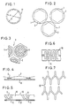
- Fig. 1 schematisch in Aufsicht ein rundes, anfiltriertes Filterkuchenelement mit angedeuteter filtrierender Fläche,
- Fig. 2 eine ähnliche Anordnung wie in Fig. 1, wobei die filtrierende Fläche Sechseckform aufweist,
- Fig. 3 schematisch und in Aufsicht eine wabenähnliche, perforierte Unterlage, wobei die Ränder unperforiert bleiben, verwendbar insbesondere für sehr dünne Filtertücher,
- Fig. 4 eine Prinzipskizze im Schnitt, darstellend Filterkuchenelemente auf einem Filtertuch mit zwischen den Filterkuchenelementen angeordneten Gewebeteilen aus unfiltrierbarem Material, dessen Dicke jedoch kleiner als die der Filterkuchenelemente ist,
- Fig. 5 schematisch im Schnitt einen Filterkuchen mit im Abstand eingedrückten Oberflächen, so daß druckverfestigte Zonen entstehen und den Filterkuchen in Filterkuchenelemente unterteilen, und
- Fig. 6 und 7 schematisch in Aufsicht Filterkuchen, die in Filterkuchenelemente unterteilt sind durch reifenprofilähnliche Formen, so daß mögliche Rißstellen gebildet sind (gesteuerte Rißstellen).
- 1 shows schematically a top view of a round, filtered filter cake element with an indicated filtering surface,
- 2 shows an arrangement similar to that in FIG. 1, the filtering surface having a hexagonal shape,
- 3 schematically and in supervision a honeycomb-like, perforated base, the edges remaining imperforate, usable in particular for very thin filter cloths,
- 4 shows a schematic diagram in section, showing filter cake elements on a filter cloth with fabric parts made of unfilterable material arranged between the filter cake elements, but whose thickness is smaller than that of the filter cake elements,
- Fig. 5 shows schematically in section a filter cake with pressed-in surfaces at a distance, so that pressure-hardened zones arise and divide the filter cake into filter cake elements, and
- Fig. 6 and 7 schematically in top view filter cakes, which are divided into filter cake elements by tire profile-like shapes, so that possible cracks are formed (controlled cracks).
Mit D ist der Durchmesser eines anfiltrierten Filterkuchenelementes 17 bezeichnet, das hier Kreisform aufweist. Der Durchmesser d der filtrierenden Fläche liegt vorzugsweise zentrisch zur Peripherie des Filterkuchenelementes; die dadurch gebildete unfiltrierbare Ringzone sollte möglichst klein gehalten werden.D denotes the diameter of a
Die Filterkuchenelemente nach Fig. 2 sind günstiger, weil die sechseckige Umrandung der filtrierenden Fläche 2 eine günstigere Anordnung mit einem geringeren Verlust an Filterflächen bietet. Der Umriß 1 des gebildeten Filterkuchen- elementes ist hier ebenfalls kreisrund. Meist werden die Filterkuchenelemente nicht symmetrisch zueinander liegen.The filter cake elements of FIG. 2 are cheaper because the hexagonal border of the
Wenn man sehr dünne Filtertücher verwendet, die keine oder nur eine geringe Querfiltration innerhalb der Filtertuchdicke zulassen, genügt es, das dünne Filtertuch auf z.B. einer wabenähnlichen Unterlage zu stützen, so daß dort kein Filterkuchen anfiltriert werden kann. Dazu kann man Unterlegbleche 3 (s. Fig. 3) mit gleich großen oder unterschiedlich großen Bohrungen 4 verwenden, die nur innerhalb des sechseckigen Fensters vorgesehen sind; die Ränder bleiben unperforiert, so daß nicht filtrierende Zonen 5 entstehen, wodurch die erfindungsgemäßen Filterkuchenelemente gebildet werden.If you use very thin filter cloths that allow little or no cross-filtration within the filter cloth thickness, it is sufficient to apply the thin filter cloth to e.g. to support a honeycomb-like base so that no filter cake can be filtered on there. For this purpose, shims 3 (see FIG. 3) with holes 4 of the same size or different sizes can be used, which are only provided within the hexagonal window; the edges remain unperforated, so that non-filtering zones 5 arise, whereby the filter cake elements according to the invention are formed.
Das Gewebe 6 aus nicht filtrierendem Material in Fig. 4 weist eine nennenswerte Dicke auf, die aber geringer als die Filterkuchendicke ist. Durch diese Gewebe 6 sind die erfindungsgemäßen Filterkuchenelemente 7 auf einem Filtertuch 8 gebildet.The
Eine weitere erfinderische Idee ist in Fig. 5 wiedergegeben. Man kann z.B. eine Wabenkonstruktion in den Filterkuchen einpressen, d.h. man kann das Filtertuch 12 belassen und den Filterkuchen auf seiner gesamten Fläche anfiltrieren und durch z.B. eine Walze Wabenprofile andrücken. Durch die eingedrückte erfinderische Oberfläche 9 verfestigt sich das anlagernde Material, so daß druckverfestigte Zonen 11 gebildet werden; zwischen diesen druckverfestigten Zonen 11 ergeben sich die erfindungsgemäßen Filterkuchenelemente 16.Another inventive idea is shown in FIG. 5. You can e.g. press a honeycomb structure into the filter cake, i.e. you can leave the
Die Filterkuchenelemente können wenigstens eine solche geometrische Form aufweisen, daß einerseits die Filterfläche, d.h. die filtrierende Fläche relativ groß und der Verlust durch den Rand möglichst klein ist, andererseits jedoch der Rand so groß ist, daß die Kuchen nicht "überziehen".The filter cake elements can have at least such a geometric shape that on the one hand the filter surface, i.e. the filtering area is relatively large and the loss through the edge is as small as possible, but on the other hand the edge is so large that the cakes do not "cover".
In Weiterentwicklung der Erfindung könnte man unter Umständen auch eine geringe Rißbildung zulassen. Diese sollte steuerbar sein, und zwar durch entsprechende Profilgebung. Solche Profilgebungen sind in den Figuren 6 und 7 zu erkennen, wobei diese gleichmäßig (also symmetrisch) oder auch ungleichmäßig gewählt werden können. Diese Profile erinnern an Reifenprofile. Durch entsprechende Ausgestaltung können gleich große oder unterschiedlich große Rißbildungszonen 13, 14, 15 gebildet werden.In a further development of the invention, a slight crack formation could possibly also be permitted. This should be controllable, by means of appropriate profiling. Such profiles can be seen in FIGS. 6 and 7, and these can be chosen to be uniform (ie symmetrical) or non-uniform. These profiles are reminiscent of tire profiles. By means of a corresponding configuration, crack
Rißbildungen sind also an solchen Stellen erlaubt, an denen das Tuch darunter unfiltrierbar ist. Mit anderen Worten ist die Rißbildung dort erlaubt, wo sowieso keine Luft durch das Tuch geführt werden kann.Cracking is therefore permitted in places where the cloth underneath is unfilterable is. In other words, crack formation is permitted where no air can be passed through the cloth anyway.
Claims (11)
Priority Applications (1)
| Application Number | Priority Date | Filing Date | Title |
|---|---|---|---|
| AT85113397T ATE52705T1 (en) | 1984-10-24 | 1985-10-22 | METHOD AND APPARATUS FOR FORMING A FILTER CAKE. |
Applications Claiming Priority (2)
| Application Number | Priority Date | Filing Date | Title |
|---|---|---|---|
| DE3438941 | 1984-10-24 | ||
| DE3438941A DE3438941C1 (en) | 1984-10-24 | 1984-10-24 | Process for forming a filter cake and device for carrying it out |
Publications (3)
| Publication Number | Publication Date |
|---|---|
| EP0179446A2 EP0179446A2 (en) | 1986-04-30 |
| EP0179446A3 EP0179446A3 (en) | 1987-08-26 |
| EP0179446B1 true EP0179446B1 (en) | 1990-05-16 |
Family
ID=6248664
Family Applications (1)
| Application Number | Title | Priority Date | Filing Date |
|---|---|---|---|
| EP85113397A Expired - Lifetime EP0179446B1 (en) | 1984-10-24 | 1985-10-22 | Method and device for the formation of a filter cake |
Country Status (5)
| Country | Link |
|---|---|
| US (1) | US4759858A (en) |
| EP (1) | EP0179446B1 (en) |
| JP (1) | JPS61103509A (en) |
| AT (1) | ATE52705T1 (en) |
| DE (2) | DE3438941C1 (en) |
Families Citing this family (1)
| Publication number | Priority date | Publication date | Assignee | Title |
|---|---|---|---|---|
| US6409929B2 (en) * | 1992-11-11 | 2002-06-25 | Bokela Ingenieurgesellschaft Fur Mechanische Verfahrenstechnik Mbh | Steam drying of rotary filter cakes without crack formation |
Family Cites Families (13)
| Publication number | Priority date | Publication date | Assignee | Title |
|---|---|---|---|---|
| US1700772A (en) * | 1925-09-19 | 1929-02-05 | Jasper A Mccaskell | Filter-cake-discharging apparatus |
| US2332917A (en) * | 1940-10-17 | 1943-10-26 | Us Rubber Co | Filtering apparatus |
| DE878795C (en) * | 1950-03-10 | 1953-10-19 | Erich Fest | Continuously working rotary filter for operation using negative or positive pressure or both at the same time |
| GB687968A (en) * | 1951-09-07 | 1953-02-25 | Cruickshank Ltd R | Filter cloths |
| CH326154A (en) * | 1953-10-19 | 1957-12-15 | Walter Fritz Dr | Filter element for precoat filter |
| US3096279A (en) * | 1959-12-23 | 1963-07-02 | Komline Sanderson Eng Corp | Flexible belt filter unit |
| US3288288A (en) * | 1963-06-28 | 1966-11-29 | Johns Manville | Art of filtration |
| US3747770A (en) * | 1969-06-20 | 1973-07-24 | Zurn Ind Inc | Filter screen |
| US3677411A (en) * | 1970-12-08 | 1972-07-18 | Ishigaki Mech Ind | Horizontally travelling-type vacuum filter |
| JPS5076186A (en) * | 1973-08-10 | 1975-06-21 | ||
| US4038187A (en) * | 1976-02-03 | 1977-07-26 | Envirex Inc. | Microscreen drum |
| DE2738239A1 (en) * | 1977-08-25 | 1979-03-01 | Kloeckner Humboldt Deutz Ag | DEVICE FOR THE PRODUCTION OF SHAPED BODIES, IN PARTICULAR ORE PELLETS FROM FILTER CAKE OF A SOLID LIQUID FILTER |
| JPS5518530A (en) * | 1978-07-24 | 1980-02-08 | Nippon Steel Corp | Manufacture of one-side turn-plated steel sheet |
-
1984
- 1984-10-24 DE DE3438941A patent/DE3438941C1/en not_active Expired
-
1985
- 1985-09-20 US US06/778,431 patent/US4759858A/en not_active Expired - Fee Related
- 1985-10-22 EP EP85113397A patent/EP0179446B1/en not_active Expired - Lifetime
- 1985-10-22 DE DE8585113397T patent/DE3577662D1/en not_active Expired - Fee Related
- 1985-10-22 AT AT85113397T patent/ATE52705T1/en not_active IP Right Cessation
- 1985-10-24 JP JP60239239A patent/JPS61103509A/en active Granted
Also Published As
| Publication number | Publication date |
|---|---|
| DE3438941C1 (en) | 1986-04-03 |
| EP0179446A3 (en) | 1987-08-26 |
| EP0179446A2 (en) | 1986-04-30 |
| JPS61103509A (en) | 1986-05-22 |
| DE3577662D1 (en) | 1990-06-21 |
| JPH0468963B2 (en) | 1992-11-04 |
| ATE52705T1 (en) | 1990-06-15 |
| US4759858A (en) | 1988-07-26 |
Similar Documents
| Publication | Publication Date | Title |
|---|---|---|
| EP0038042B1 (en) | Filtration device | |
| DE2216342A1 (en) | Method and device for separating a muddy liquid into its solid and aqueous components | |
| DE1786467B2 (en) | Process for filtering and filter press for carrying out the process. Elimination from: 1536764 | |
| DE2658578C2 (en) | Device for dewatering thickened sludge | |
| DE2519269A1 (en) | MOLD CONSTRUCTION | |
| EP0179446B1 (en) | Method and device for the formation of a filter cake | |
| DE2854168C3 (en) | Belt filter press for the continuous dewatering of a suspension, in particular a waste water sludge | |
| DE2756892C2 (en) | Centrifugal cleaning filter | |
| DE7825040U1 (en) | DEVICE FOR CONTINUOUS, LIQUID-SEPARATING EXPRESSION OF MATERIAL | |
| DE2123379A1 (en) | Fiber mat | |
| DE930796C (en) | Press and method for the radial extrusion of oils, juices, etc. like | |
| DE3150641A1 (en) | Device for filtering and thickening thin sludge | |
| DE100270T1 (en) | EXTRACTION METHOD OF A LIQUID PHASE FROM A MIRROR-LIKE MATERIAL. | |
| EP0863252B1 (en) | Process and apparatus to dewater a fiber suspension | |
| DE947463C (en) | Backwashable gap filter made of thin layers of textile or fiber material stacked on top of one another | |
| DE1461479A1 (en) | Filter plate and process for its manufacture | |
| DE576527C (en) | Continuously working suction cell rotary filter | |
| DE2323516C3 (en) | Chamber filter plate | |
| DE3824995C2 (en) | ||
| DE4013597C1 (en) | Dewatering of sludge - by pressing, thin pressing filtrate out of sludge layer, stacking then sludge layers on top of each other, etc. | |
| DE877742C (en) | Device for the filtration of liquids | |
| DE3212646C2 (en) | ||
| DE3809372A1 (en) | Filter | |
| DE2518463C3 (en) | Filter device | |
| DE649558C (en) | Apparatus for the manufacture of molded sealing bodies |
Legal Events
| Date | Code | Title | Description |
|---|---|---|---|
| PUAI | Public reference made under article 153(3) epc to a published international application that has entered the european phase |
Free format text: ORIGINAL CODE: 0009012 |
|
| AK | Designated contracting states |
Kind code of ref document: A2 Designated state(s): AT BE CH DE FR GB IT LI LU NL SE |
|
| PUAL | Search report despatched |
Free format text: ORIGINAL CODE: 0009013 |
|
| AK | Designated contracting states |
Kind code of ref document: A3 Designated state(s): AT BE CH DE FR GB IT LI LU NL SE |
|
| 17P | Request for examination filed |
Effective date: 19870724 |
|
| 17Q | First examination report despatched |
Effective date: 19880204 |
|
| GRAA | (expected) grant |
Free format text: ORIGINAL CODE: 0009210 |
|
| AK | Designated contracting states |
Kind code of ref document: B1 Designated state(s): AT BE CH DE FR GB IT LI LU NL SE |
|
| REF | Corresponds to: |
Ref document number: 52705 Country of ref document: AT Date of ref document: 19900615 Kind code of ref document: T |
|
| REF | Corresponds to: |
Ref document number: 3577662 Country of ref document: DE Date of ref document: 19900621 |
|
| GBT | Gb: translation of ep patent filed (gb section 77(6)(a)/1977) | ||
| ITF | It: translation for a ep patent filed |
Owner name: STUDIO JAUMANN |
|
| ET | Fr: translation filed | ||
| PG25 | Lapsed in a contracting state [announced via postgrant information from national office to epo] |
Ref country code: LU Free format text: LAPSE BECAUSE OF NON-PAYMENT OF DUE FEES Effective date: 19901031 |
|
| PLBE | No opposition filed within time limit |
Free format text: ORIGINAL CODE: 0009261 |
|
| STAA | Information on the status of an ep patent application or granted ep patent |
Free format text: STATUS: NO OPPOSITION FILED WITHIN TIME LIMIT |
|
| 26N | No opposition filed | ||
| PG25 | Lapsed in a contracting state [announced via postgrant information from national office to epo] |
Ref country code: DE Effective date: 19910702 |
|
| ITTA | It: last paid annual fee | ||
| PGFP | Annual fee paid to national office [announced via postgrant information from national office to epo] |
Ref country code: NL Payment date: 19911031 Year of fee payment: 7 |
|
| PGFP | Annual fee paid to national office [announced via postgrant information from national office to epo] |
Ref country code: SE Payment date: 19920928 Year of fee payment: 8 |
|
| PGFP | Annual fee paid to national office [announced via postgrant information from national office to epo] |
Ref country code: AT Payment date: 19921002 Year of fee payment: 8 |
|
| PGFP | Annual fee paid to national office [announced via postgrant information from national office to epo] |
Ref country code: GB Payment date: 19921012 Year of fee payment: 8 |
|
| PGFP | Annual fee paid to national office [announced via postgrant information from national office to epo] |
Ref country code: BE Payment date: 19921019 Year of fee payment: 8 |
|
| PGFP | Annual fee paid to national office [announced via postgrant information from national office to epo] |
Ref country code: FR Payment date: 19921027 Year of fee payment: 8 Ref country code: CH Payment date: 19921027 Year of fee payment: 8 |
|
| PG25 | Lapsed in a contracting state [announced via postgrant information from national office to epo] |
Ref country code: NL Effective date: 19930501 |
|
| NLV4 | Nl: lapsed or anulled due to non-payment of the annual fee | ||
| PG25 | Lapsed in a contracting state [announced via postgrant information from national office to epo] |
Ref country code: GB Effective date: 19931022 Ref country code: AT Effective date: 19931022 |
|
| PG25 | Lapsed in a contracting state [announced via postgrant information from national office to epo] |
Ref country code: SE Effective date: 19931023 |
|
| PG25 | Lapsed in a contracting state [announced via postgrant information from national office to epo] |
Ref country code: LI Effective date: 19931031 Ref country code: CH Effective date: 19931031 Ref country code: BE Effective date: 19931031 |
|
| BERE | Be: lapsed |
Owner name: ZURICHER BEUTELTUCHFABRIK A.G. Effective date: 19931031 |
|
| GBPC | Gb: european patent ceased through non-payment of renewal fee |
Effective date: 19931022 |
|
| PG25 | Lapsed in a contracting state [announced via postgrant information from national office to epo] |
Ref country code: FR Effective date: 19940630 |
|
| REG | Reference to a national code |
Ref country code: CH Ref legal event code: PL |
|
| REG | Reference to a national code |
Ref country code: FR Ref legal event code: ST |
|
| EUG | Se: european patent has lapsed |
Ref document number: 85113397.5 Effective date: 19940510 |