US3288288A - Art of filtration - Google Patents
Art of filtration Download PDFInfo
- Publication number
- US3288288A US3288288A US291577A US29157763A US3288288A US 3288288 A US3288288 A US 3288288A US 291577 A US291577 A US 291577A US 29157763 A US29157763 A US 29157763A US 3288288 A US3288288 A US 3288288A
- Authority
- US
- United States
- Prior art keywords
- cake
- filter
- drum
- filter cake
- tamper
- Prior art date
- Legal status (The legal status is an assumption and is not a legal conclusion. Google has not performed a legal analysis and makes no representation as to the accuracy of the status listed.)
- Expired - Lifetime
Links
- 238000001914 filtration Methods 0.000 title claims description 18
- 239000012065 filter cake Substances 0.000 claims description 39
- 239000007788 liquid Substances 0.000 claims description 7
- 238000000034 method Methods 0.000 claims description 7
- 230000009471 action Effects 0.000 claims description 6
- 230000003750 conditioning effect Effects 0.000 claims description 2
- 230000008569 process Effects 0.000 claims description 2
- 239000002002 slurry Substances 0.000 description 11
- 239000007787 solid Substances 0.000 description 8
- 238000001035 drying Methods 0.000 description 7
- XLYOFNOQVPJJNP-UHFFFAOYSA-N water Substances O XLYOFNOQVPJJNP-UHFFFAOYSA-N 0.000 description 6
- 229910052918 calcium silicate Inorganic materials 0.000 description 5
- 239000000378 calcium silicate Substances 0.000 description 5
- OYACROKNLOSFPA-UHFFFAOYSA-N calcium;dioxido(oxo)silane Chemical compound [Ca+2].[O-][Si]([O-])=O OYACROKNLOSFPA-UHFFFAOYSA-N 0.000 description 5
- 229910052751 metal Inorganic materials 0.000 description 5
- 239000002184 metal Substances 0.000 description 5
- 230000009467 reduction Effects 0.000 description 5
- 238000005406 washing Methods 0.000 description 5
- 241000237858 Gastropoda Species 0.000 description 4
- 239000000463 material Substances 0.000 description 4
- 238000010981 drying operation Methods 0.000 description 3
- 239000000047 product Substances 0.000 description 3
- 238000003828 vacuum filtration Methods 0.000 description 3
- KHOITXIGCFIULA-UHFFFAOYSA-N Alophen Chemical compound C1=CC(OC(=O)C)=CC=C1C(C=1N=CC=CC=1)C1=CC=C(OC(C)=O)C=C1 KHOITXIGCFIULA-UHFFFAOYSA-N 0.000 description 2
- 230000006835 compression Effects 0.000 description 2
- 238000007906 compression Methods 0.000 description 2
- 239000000446 fuel Substances 0.000 description 2
- 238000009434 installation Methods 0.000 description 2
- 230000001788 irregular Effects 0.000 description 2
- 230000007246 mechanism Effects 0.000 description 2
- 235000020030 perry Nutrition 0.000 description 2
- 230000003014 reinforcing effect Effects 0.000 description 2
- 230000035939 shock Effects 0.000 description 2
- 229920000742 Cotton Polymers 0.000 description 1
- 230000015572 biosynthetic process Effects 0.000 description 1
- 239000011248 coating agent Substances 0.000 description 1
- 238000000576 coating method Methods 0.000 description 1
- 238000007599 discharging Methods 0.000 description 1
- 239000004744 fabric Substances 0.000 description 1
- 238000012986 modification Methods 0.000 description 1
- 230000004048 modification Effects 0.000 description 1
- 239000012452 mother liquor Substances 0.000 description 1
- 230000002787 reinforcement Effects 0.000 description 1
- 239000012858 resilient material Substances 0.000 description 1
- 239000011435 rock Substances 0.000 description 1
- 239000000126 substance Substances 0.000 description 1
Images

Classifications
-
- B—PERFORMING OPERATIONS; TRANSPORTING
- B01—PHYSICAL OR CHEMICAL PROCESSES OR APPARATUS IN GENERAL
- B01D—SEPARATION
- B01D33/00—Filters with filtering elements which move during the filtering operation
- B01D33/044—Filters with filtering elements which move during the filtering operation with filtering bands or the like supported on cylinders which are pervious for filtering
- B01D33/048—Filters with filtering elements which move during the filtering operation with filtering bands or the like supported on cylinders which are pervious for filtering with endless filtering bands
-
- B—PERFORMING OPERATIONS; TRANSPORTING
- B01—PHYSICAL OR CHEMICAL PROCESSES OR APPARATUS IN GENERAL
- B01D—SEPARATION
- B01D33/00—Filters with filtering elements which move during the filtering operation
- B01D33/06—Filters with filtering elements which move during the filtering operation with rotary cylindrical filtering surfaces, e.g. hollow drums
- B01D33/073—Filters with filtering elements which move during the filtering operation with rotary cylindrical filtering surfaces, e.g. hollow drums arranged for inward flow filtration
Definitions
- This invention relates to rotary vacuum filters and particularly to a technique for increasing the amount of water or other liquids removed from slurries during rotary vacuum filtration.
- the invention also improves the size uniformity of the filter cake chips discharged from the filter. It is particularly adapted for filtration of calcium silicate slurries.
- continuous filtration processes involve the use of a slowly rotating cylinder or drum having a porous filtering medium on its outer surface and means for producing a partial vacuum within the interior of the drum.
- the drum is generally horizontally mounted so that the lower portion of its periphery revolves within a tank containing a slurry of the material to be recovered by filtration.
- a single revolution of the filter it picks up a coating of slurry, withdraws a portion of the mother liquor, thereby forming a loose cake of the material, moves the cake past washing and compressing means, withdraws the washing liquid from the cake, and removes the cake from the drum immediately before completion of the revolution.
- washing and compressing means comprise a porous belt which is held in pressure contact to travel with the filter cake during a portion of its revolution, and a cooperating source of washing liquid which wets the belt. The liquid is sucked successively through the belt, the filter cake, and the porous filtering medium of the drum.
- Fabric belts such as cotton sheeting, have been employed for washing and compacting the filter cake.
- Suitable means for reinforcement of .the cake and for ultimately stripping it from the drum are also associated with the filter.
- This arrangement may, for example, comprise a plurality of spaced strings such as illustrated in United States Letters Patent No. 2,197,610 to Fedeler.
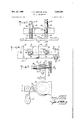
- FIGURE 1 illustrates a diagrammatic sideelevation, shown partially in cross section, of a rotary vacuumfilter constructed in accordance with the instant invention
- FIGURE 2 is a partial end view taken along line 22 of FIGURE 1 showing the removal of filter cake chips from the strings;
- FIGURE 3 is an enlarged detailed view of a portion of the compressing means or tamper head of the instantinvention
- FIGURE 4 is an enlarged detailed rear elevation view of the structure shown in FIGURE 3.
- FIGURE 5 is an enlarged cross-sectional view of the tamper head taken along line 55 of FIGURE 3.
- FIGURE 1 illustrates a rotary vacuum filter 10, comprising a revolvable hollow drum 50 covered with a filter medium and having suitable vacuum producing means (not shown) and a novel compressing means exemplified by tamper 20.
- the motivating means for the tamper comprises a motor driven eccentric 12 attached by suitable linkage, illustrated generally by reference numeral 13, to a lever arm 14 mounted on and attached rigidly to shaft 16, which is journaled on lugs 17 of the stationary framework 19.
- a number of arms 18 are attached rigidly to shaft 16 and provide mounting bracket portions 21 for supporting tamper 20 adjacent the external periphery of drum 50. Through the mechanism described, eccentric 12 rocks arms 18 through a limited are about the axis of shaft 16.
- the tamper 20 comprises a squeezing strip 22 of a pliable. material such as rubber extending continuously across the face of the filter drum 50 and secured at spaced intervals to a plurality of spaced reinforcing metal plates 26 by bolts 27 having their heads countersunk in strip 22, as illustrated at 29. Gaps 28 occur between the ends of metal plates 26.
- a shaft 30 is attached to each of the metal plates 26, as by a headed fastener 25 (FIG. 5), and is mounted for reciprocation in bushings 32.
- Bushings 32 are fixed in bracket portions 21 of arms 18.
- a shock absorbing bushing cup 34 made of suitable resilient material, such as rubber, is fitted about the end of each shaft 30 opposite the end to which the tamper 20 is fixed.
- the rim end of the bushing cup 34 fits slidingly over bushings 32.
- Lock nuts 38 retain bushing cup 34 on the end of the shaft.
- Compression coil spring 36 is coaxial with and surrounds shaft 30 and bushing 32. The ends of each coil spring 36 abut respectively against a bracket portion 21 and metal plate 26, and the springs 36 urge the plates 26 away from the bracket portions 21 and normally cause the rims of bushing cups 34 to abut the bracket portions 21 and the interiors of the bottoms of the cups 34 to abut the ends of bushings 32.
- the tamper 20 is mounted at an angle to the tangent to the filter drum with the forward edge, the edge in the direction of rotation, closer to the drum than the backward edge.
- the individually mounted plates 26 cause the tamper 20 to conform more closely to the surface of the filter cake than it would if it were backed by a continuous bar, since this arrangement permits the rubber strip 22 to flex at local segments along its length.
- eccentric 12 operates through the mechanism described above to cause tamper to impart repeated vibratory action to the filter cake layer and causes the tamper alternately to press down on and then to withdraw from the surface of the filter cake.
- shafts 30 are permitted to reciprocate in bushings 32 for a short distance against the action of springs 36, temporarily disengaging the rims of shock absorbing bushing cups 34 from abutment with bracket portions 21.
- bracket portions 21 again abut the rims of cups 34 and tamper 20 is lifted away from the cake, preparatory to another tampering cycle.
- This squeezing action applied to the surface of the filter cake produces a serrated profile 40 and also works or puddles the cake so as to minimize formation of cracks commonly present with many materials being filtered on rotary drum filters.
- the pressed cake 42 is readily removed from the surface of the filter drum by the conventionally employed strings 44. As the strings pass around the discharge roller 46 the cake is discharged in the form of uniformly sized chips 48 onto conveyor 50, to be carried to a drying oven (not shown).
- Example A conventional rotary drum vacuum string filter eight feet in diameter and ten feet wide was conventionally operated to filter a slurry of calcium silicate.
- the cake was discharged onto a conveyor belt which carried it through a dryer of conventional design.
- the cake was soft.
- Part of the filter cake was discharged from the filter in the form of slabs which tended to fold and.
- the filter cake discharged from the filter averaged 87.3% moisture and 12.7% solids, that is, from each 100 pounds of solids there were 687 pounds of water to be evaporated in the subsequent drying operations.
- the tamper as described'above, was then installed on the filter as indicated in FIGURE 1.
- the rubberstrip was A2 inch thick by 4 inches wide and extended across the full ten foot width of the filter. Each metal plate was 4 inches wide and 5 inches long. The plates were spaced inch apart. The springs were adjusted by the nuts so that the plate would apply a pressure of 3 to 4 pounds per square inch.
- the eccentric was rotated at a speed to produce 280 squeezings per minute on the surface of the filter cake with the drum operating at 0.8 r.p.m., and produced a serrated filter cake profile.
- the filter cake came free from the filter drum with no carry-back.
- the cake was relatively uniform in thickness and discharged as chips 1 to 2 inches wide by 2 to 3 inches long.
- the chips fell onto the conveyor drier belt in a layer of uniform thickness and formed a bed through which the heated drying air could pass much more readily than that of the previous cake.
- the chips contained 85.0% moisture and 15.0% solids, so that each 100 pounds of solids contained 567 pounds of water to be evaporated in subsequent drying operations.
- the use of the tamper has minimized the incidence of wet slugs of filter cake which cause the drying process to go out of control and the product to be rejected because of excess moisture content.
- the percentage of finished productpreviously rejected was 2.12% whereas after the installation of the tamper this was reduced to 0.6%.
- a filtering device comprising a revolvable hollow drum, filter medium covering the drum periphery, means mit said drum to be partially contained therewithin, means for creating vacuum within said drum to form a filter cake on the filter medium as the drum revolves through said slurry, substantially flat-surfaced compressing means of substantial width extending the width of said drum, a substantial portion of the total surface of which is capable of contacting the filter cake at an angle to the tangent of the filter drum, and means to actuate said compressing means for imparting a repeated serrated profile to the surface of the filter cake formed on the filter medium of such a nature that the individual serrations extend for substantially the total width of the cake and are substantially contiguous one to another.
- a filtering device as described in claim 1 wherein said compressing means comprises a continuous flat pli- 15 able strip connected to and backed by a plurality of reinforcing plates so as to produce relatively small serrations upon a filter cake which breaks into substantially uniform chips when the cake is discharged.
- a continuous filtering process comprising forming a filter cake on a revolving filter medium, conditioning said cake by Withdrawing a portion of liquid therefrom through the filter medium, subjecting successive portions of the filter cake to repeating compressing action as it revolves by contacting a substantial portion of the total surface of a substantially fiat means at an angle to the tangent of said cake and imparting a serrated profile to the surface of the filter cake, whereby the individual serrations extend for substantially the total width of the cake and are substantially contiguous one to another.
Landscapes
- Chemical & Material Sciences (AREA)
- Chemical Kinetics & Catalysis (AREA)
- Filtration Of Liquid (AREA)
Description
Nov. 29, 1966 T. P. HORTON ETAL 3, 3
ART OF FILTRATION 2 Sheets-Sheet 1 Filed June 28, 1963 INVENTORS ZZz/M/w P. %/o/Pr0/v laws .6." Own/MW g4 X2 Z;
ATTORNEY 2 Sheets-Sheet 2 T. P. HORTON ETAL ART OF FILTRATION Nov. 29, 1966 Flled June 28 1963 United States Patent 3,288,288 ART OF FILTRATION Truman P. Horton and Louis E. Capshaw, Lompoc, Calif., assignors to Johns-Manville Corporation, New York, N.Y., a corporation of New York Filed June 28, 1963, Ser. No. 291,577 3 Claims. (Cl. 21066) This invention relates to rotary vacuum filters and particularly to a technique for increasing the amount of water or other liquids removed from slurries during rotary vacuum filtration. The invention also improves the size uniformity of the filter cake chips discharged from the filter. It is particularly adapted for filtration of calcium silicate slurries.
Currently, continuous filtration processes involve the use of a slowly rotating cylinder or drum having a porous filtering medium on its outer surface and means for producing a partial vacuum within the interior of the drum. The drum is generally horizontally mounted so that the lower portion of its periphery revolves within a tank containing a slurry of the material to be recovered by filtration. During a single revolution of the filter, it picks up a coating of slurry, withdraws a portion of the mother liquor, thereby forming a loose cake of the material, moves the cake past washing and compressing means, withdraws the washing liquid from the cake, and removes the cake from the drum immediately before completion of the revolution.
Conventional washing and compressing means comprise a porous belt which is held in pressure contact to travel with the filter cake during a portion of its revolution, and a cooperating source of washing liquid which wets the belt. The liquid is sucked successively through the belt, the filter cake, and the porous filtering medium of the drum. Fabric belts, such as cotton sheeting, have been employed for washing and compacting the filter cake.
Suitable means for reinforcement of .the cake and for ultimately stripping it from the drum are also associated with the filter. This arrangement may, for example, comprise a plurality of spaced strings such as illustrated in United States Letters Patent No. 2,197,610 to Fedeler.
The major problems of such filtration techniques have been in facilitating and reducing the cost of subsequent drying operations by achieving sutficient reduction of moisture content of the filter cake, producing uniform cake thickness, and discharging uniformly sized pieces or chips of the cake from the filter.
These problems have been particularly evident in removing water from calcium silicate slurries. The slurry is first filtered on a rotary drum filter, such as described above, to remove the bulk of the water, and the discharged filter cake passed through a drier. Because of the inherent high moisture-retaining property of calcium silicate, rotary vacuum filters have performed poorly. Portions of the filter cake have remained on the filter drum because the cake has not been firm enough to be removed from the filter by the strings. Consequently, these portions form carry-back areas which become thicker with each revolution of the filter drum. When they finally become dislodged they produce what might be termed wet slugs of filter cake which are not completely dried. The drying problem is made more difficult by the varied sized chips discharged from the drum because of the insufiicient filtering of the cake.
Various means have been advanced to overcome these problems. Compression rolls have been used to squeeze the cake and reduce cake moisture and are illustrated in Perrys Chemical Engineers Handbook, Third Edition, page 978, and US. Letters Patent Nos. 2,197,610, mentioned above, and 2,564,515 to Vogel. Flappers to slap the cake so as to reduce cake moisture have also been tried. See for instance, Perry, supra, page 991, and US. Letters Patent No. 2,735,550 to Fagerberg.
Although these devices have been partially successful, the problems, particularly with regard to calcium silicate slurries, have persisted. None of these above-mentioned devices have improved the reduction of moisture content, nor aided in controlling the size of the chips discharged from the filter.
It is therefore a principal object of the instant invention to provide filter cake compressing means for more efficient and economical rotary filtration.
It is an additional object of this invention to provide means to increase the amount of water and other liquids removed from solids during rotary vacuum filtration and to control the size of the filter cake chips discharged from the filter.
It is another object of this invention to provide a technique to reduce filter cake carry-back in rotary vacuum filtration and to improve the uniformity in filter cake thickness.
It is still a further object to provide a technique of producing more uniform filter cake chips with lower moisture content and thereby increase the efliciency of subsequent drying processes.
It has now been discovered that the foregoing objects may be satisfied and the above-mentioned disadvantages overcome by providing compressing means to impart a serrated profile on the surface of the filter cake through a repeated squeezing action as the filter drum rotates.
Our invention will be more fully understood, and additional objects and further scope of applicability of the present invention will become apparent from the detailed description given hereinafter, the preferred embodiment of which has been illustrated in the accompanying draw.- ings by way of example only, wherein:
FIGURE 1 illustrates a diagrammatic sideelevation, shown partially in cross section, of a rotary vacuumfilter constructed in accordance with the instant invention;
FIGURE 2 is a partial end view taken along line 22 of FIGURE 1 showing the removal of filter cake chips from the strings;
FIGURE 3 is an enlarged detailed view of a portion of the compressing means or tamper head of the instantinvention;
FIGURE 4 is an enlarged detailed rear elevation view of the structure shown in FIGURE 3; and
FIGURE 5 is an enlarged cross-sectional view of the tamper head taken along line 55 of FIGURE 3.
With reference to the drawings, wherein like reference numbers refer to like parts throughout, FIGURE 1 illustrates a rotary vacuum filter 10, comprising a revolvable hollow drum 50 covered with a filter medium and having suitable vacuum producing means (not shown) and a novel compressing means exemplified by tamper 20. The motivating means for the tamper comprises a motor driven eccentric 12 attached by suitable linkage, illustrated generally by reference numeral 13, to a lever arm 14 mounted on and attached rigidly to shaft 16, which is journaled on lugs 17 of the stationary framework 19. A number of arms 18 are attached rigidly to shaft 16 and provide mounting bracket portions 21 for supporting tamper 20 adjacent the external periphery of drum 50. Through the mechanism described, eccentric 12 rocks arms 18 through a limited are about the axis of shaft 16.
As shown in more detail in FIGURES 3, 4 and 5, the tamper 20 comprises a squeezing strip 22 of a pliable. material such as rubber extending continuously across the face of the filter drum 50 and secured at spaced intervals to a plurality of spaced reinforcing metal plates 26 by bolts 27 having their heads countersunk in strip 22, as illustrated at 29. Gaps 28 occur between the ends of metal plates 26. A shaft 30 is attached to each of the metal plates 26, as by a headed fastener 25 (FIG. 5), and is mounted for reciprocation in bushings 32. Bushings 32 are fixed in bracket portions 21 of arms 18. A shock absorbing bushing cup 34 made of suitable resilient material, such as rubber, is fitted about the end of each shaft 30 opposite the end to which the tamper 20 is fixed. The rim end of the bushing cup 34 fits slidingly over bushings 32. Lock nuts 38 retain bushing cup 34 on the end of the shaft. Compression coil spring 36 is coaxial with and surrounds shaft 30 and bushing 32. The ends of each coil spring 36 abut respectively against a bracket portion 21 and metal plate 26, and the springs 36 urge the plates 26 away from the bracket portions 21 and normally cause the rims of bushing cups 34 to abut the bracket portions 21 and the interiors of the bottoms of the cups 34 to abut the ends of bushings 32.
The tamper 20 is mounted at an angle to the tangent to the filter drum with the forward edge, the edge in the direction of rotation, closer to the drum than the backward edge. The individually mounted plates 26 cause the tamper 20 to conform more closely to the surface of the filter cake than it would if it were backed by a continuous bar, since this arrangement permits the rubber strip 22 to flex at local segments along its length.
As the filter drum rotates it draws slurry 24 against its surface forming a filter cake. At the same time eccentric 12 operates through the mechanism described above to cause tamper to impart repeated vibratory action to the filter cake layer and causes the tamper alternately to press down on and then to withdraw from the surface of the filter cake. As the tamper strikes the surface of the cake, shafts 30 are permitted to reciprocate in bushings 32 for a short distance against the action of springs 36, temporarily disengaging the rims of shock absorbing bushing cups 34 from abutment with bracket portions 21. As arms 18 are rocked away from the cake, the bracket portions 21 again abut the rims of cups 34 and tamper 20 is lifted away from the cake, preparatory to another tampering cycle. This squeezing action applied to the surface of the filter cake produces a serrated profile 40 and also works or puddles the cake so as to minimize formation of cracks commonly present with many materials being filtered on rotary drum filters.
As shown in FIGURES 1 and 2, the pressed cake 42 is readily removed from the surface of the filter drum by the conventionally employed strings 44. As the strings pass around the discharge roller 46 the cake is discharged in the form of uniformly sized chips 48 onto conveyor 50, to be carried to a drying oven (not shown).
The following example will illustrate the invention.
Example A conventional rotary drum vacuum string filter eight feet in diameter and ten feet wide was conventionally operated to filter a slurry of calcium silicate. The cake was discharged onto a conveyor belt which carried it through a dryer of conventional design. The cake was soft. Part of the filter cake was discharged from the filter in the form of slabs which tended to fold and.
break off as they fell onto the conveyor belt. Other parts Were discharged as chips varying in size from tiny pieces to large chunks. Still other parts stuck to the filter drum. When these parts made additional passes through the slurry they became thicker and higher in moisture content than the rest of the cake. Finally when they did come free from the filter drum they fell onto the conveyor belt in the form of wet slugs. The bed of filter cake, irregular sized chips and wet slugs, was irregular in thickness and tended to hinder the passage of drying air through it.
The filter cake discharged from the filter averaged 87.3% moisture and 12.7% solids, that is, from each 100 pounds of solids there were 687 pounds of water to be evaporated in the subsequent drying operations.
The tamper, as described'above, was then installed on the filter as indicated in FIGURE 1. The rubberstrip was A2 inch thick by 4 inches wide and extended across the full ten foot width of the filter. Each metal plate was 4 inches wide and 5 inches long. The plates were spaced inch apart. The springs were adjusted by the nuts so that the plate would apply a pressure of 3 to 4 pounds per square inch. The eccentric was rotated at a speed to produce 280 squeezings per minute on the surface of the filter cake with the drum operating at 0.8 r.p.m., and produced a serrated filter cake profile.
The filter cake came free from the filter drum with no carry-back. The cake was relatively uniform in thickness and discharged as chips 1 to 2 inches wide by 2 to 3 inches long. The chips fell onto the conveyor drier belt in a layer of uniform thickness and formed a bed through which the heated drying air could pass much more readily than that of the previous cake.
None of the above-mentioned prior art devices pressed successive small elements of the filter cake to produce a slightly serrated profile which has proven to aid in controlling the size of the chips discharged from the filter.
The chips contained 85.0% moisture and 15.0% solids, so that each 100 pounds of solids contained 567 pounds of water to be evaporated in subsequent drying operations.
Comparing results with respect to moisture content of the filter cake illustrated 17.5%. reduction in the moisture to be evaporated by the drier:
Pounds Moisture per 100 lbs. of solids without tamper 687 Moisture per 100 lbs. of solids with tamper 567 Reduction per 100 lbs. of solids 120 The relative drying efliciency of the two techniques was evaluated by comparing the needed drier fuel consumption per ton of product. Before the tamper means was installed 22,958 cu. ft. of gas were required as opposed to 20,145 cu. ft. after, or a 12.25% reduction in fuel per ton of product.
Additionally, the use of the tamper has minimized the incidence of wet slugs of filter cake which cause the drying process to go out of control and the product to be rejected because of excess moisture content. The percentage of finished productpreviously rejected was 2.12% whereas after the installation of the tamper this was reduced to 0.6%.
Operating on maximum throughout, the average filtration rates in tons per 24 hours were 36.397 before the installation of the tamper and 42.778 after, for a net filtration rate increase of 17.53%.
While the instant invention is particularly applicable to rotary vacuum filters employing a string discharge system, it may be used with other rotary filters.
It is believed the above provides a complete description of the invention in such manner as to distinguish it from other inventions and from what is old, and provides a description of the best mode contemplated of carrying out the invention and thereby complies with the patent statutes. It is to be understood that variations and modifications of the invention, as illustrated by the specific example herein, may be made without departing from the spirit of the invention. It is also to be understood that the scope of the invention is not to be interpreted as limited to the specific embodiments disclosed herein but only in accordance with the appended claims, when read in the light of the foregoing description.
What we claim is:
1. A filtering device comprising a revolvable hollow drum, filter medium covering the drum periphery, means mit said drum to be partially contained therewithin, means for creating vacuum within said drum to form a filter cake on the filter medium as the drum revolves through said slurry, substantially flat-surfaced compressing means of substantial width extending the width of said drum, a substantial portion of the total surface of which is capable of contacting the filter cake at an angle to the tangent of the filter drum, and means to actuate said compressing means for imparting a repeated serrated profile to the surface of the filter cake formed on the filter medium of such a nature that the individual serrations extend for substantially the total width of the cake and are substantially contiguous one to another.
2. A filtering device as described in claim 1 wherein said compressing means comprises a continuous flat pli- 15 able strip connected to and backed by a plurality of reinforcing plates so as to produce relatively small serrations upon a filter cake which breaks into substantially uniform chips when the cake is discharged.
3. A continuous filtering process comprising forming a filter cake on a revolving filter medium, conditioning said cake by Withdrawing a portion of liquid therefrom through the filter medium, subjecting successive portions of the filter cake to repeating compressing action as it revolves by contacting a substantial portion of the total surface of a substantially fiat means at an angle to the tangent of said cake and imparting a serrated profile to the surface of the filter cake, whereby the individual serrations extend for substantially the total width of the cake and are substantially contiguous one to another.
References Cited by the Examiner UNITED STATES PATENTS 2,197,610 4/1940 Fedeler 210-386 X FOREIGN PATENTS 481,037 3/1938 Great Britain. 722,067 1/ 1955 Great Britain. 739,293 10/ 1955 Great Britain.
20 REUBEN FRIEDMAN, Primary Examiner.
SAM ZAHARNA, Assistant Examiner.
Claims (1)
- 3. A CONTINUOUS FILTERING PROCESS COMPRISING FORMING A FILTER CAKE ON A REVOLVING FILTER MEDIUM, CONDITIONING SAID CAKE BY WITHDRAWING A PORTION OF LIQUID THEREFROM THROUGH THE FILTER MEDIUM, SUBJECTING SUCCESSIVE PORTIONS OF THE FILTER CAKE TO REPEATING COMPRESSING ACTION AS IT REVOLVES BY CONTACTING A SUBSTANTIAL PORTION OF THE TOTAL SURFACE OF A SUBSTANTIALLY FLAT MEANS AT AN ANGLE TO THE TANGENT OF SAID CAKE AND IMPARTING A SERRATED PROFILE TO THE SURFACE OF THE FILTER CAKE, WHEREBY THE INDIVIDUAL SERRATIONS EXTEND FOR SUBSTANTIALLY THE TOTAL WIDTH OF THE CAKE AND ARE SUBSTANTIALLY CONTIGUOUS ONE TO ANOTHER.
Priority Applications (1)
| Application Number | Priority Date | Filing Date | Title |
|---|---|---|---|
| US291577A US3288288A (en) | 1963-06-28 | 1963-06-28 | Art of filtration |
Applications Claiming Priority (1)
| Application Number | Priority Date | Filing Date | Title |
|---|---|---|---|
| US291577A US3288288A (en) | 1963-06-28 | 1963-06-28 | Art of filtration |
Publications (1)
| Publication Number | Publication Date |
|---|---|
| US3288288A true US3288288A (en) | 1966-11-29 |
Family
ID=23120875
Family Applications (1)
| Application Number | Title | Priority Date | Filing Date |
|---|---|---|---|
| US291577A Expired - Lifetime US3288288A (en) | 1963-06-28 | 1963-06-28 | Art of filtration |
Country Status (1)
| Country | Link |
|---|---|
| US (1) | US3288288A (en) |
Cited By (3)
| Publication number | Priority date | Publication date | Assignee | Title |
|---|---|---|---|---|
| EP0179446A3 (en) * | 1984-10-24 | 1987-08-26 | Zuricher Beuteltuchfabrik Ag | Method and device for the formation of a filter cake |
| US4747961A (en) * | 1986-12-19 | 1988-05-31 | Atlantic Richfield Company | Method and system for treating drill cutting slurries and the like |
| US6605728B2 (en) * | 1999-12-17 | 2003-08-12 | Warner-Lambert Company | Process for producing crystalline atorvastatin calcium |
Citations (4)
| Publication number | Priority date | Publication date | Assignee | Title |
|---|---|---|---|---|
| GB481037A (en) * | 1936-04-28 | 1938-03-04 | Asano Cement Kabushiki Kaisha | Improvements in or relating to vacuum filters |
| US2197610A (en) * | 1938-06-09 | 1940-04-16 | Thos C Stephens | Filter installation and filtering procedure |
| GB722067A (en) * | 1952-08-13 | 1955-01-19 | Davey Paxman And Company Ltd | Improvements in or relating to rotary drum filters for liquids |
| GB739293A (en) * | 1953-05-26 | 1955-10-26 | Davey Paxman And Company Ltd | Improvements in or relating to rotary vacuum filters |
-
1963
- 1963-06-28 US US291577A patent/US3288288A/en not_active Expired - Lifetime
Patent Citations (4)
| Publication number | Priority date | Publication date | Assignee | Title |
|---|---|---|---|---|
| GB481037A (en) * | 1936-04-28 | 1938-03-04 | Asano Cement Kabushiki Kaisha | Improvements in or relating to vacuum filters |
| US2197610A (en) * | 1938-06-09 | 1940-04-16 | Thos C Stephens | Filter installation and filtering procedure |
| GB722067A (en) * | 1952-08-13 | 1955-01-19 | Davey Paxman And Company Ltd | Improvements in or relating to rotary drum filters for liquids |
| GB739293A (en) * | 1953-05-26 | 1955-10-26 | Davey Paxman And Company Ltd | Improvements in or relating to rotary vacuum filters |
Cited By (3)
| Publication number | Priority date | Publication date | Assignee | Title |
|---|---|---|---|---|
| EP0179446A3 (en) * | 1984-10-24 | 1987-08-26 | Zuricher Beuteltuchfabrik Ag | Method and device for the formation of a filter cake |
| US4747961A (en) * | 1986-12-19 | 1988-05-31 | Atlantic Richfield Company | Method and system for treating drill cutting slurries and the like |
| US6605728B2 (en) * | 1999-12-17 | 2003-08-12 | Warner-Lambert Company | Process for producing crystalline atorvastatin calcium |
Similar Documents
| Publication | Publication Date | Title |
|---|---|---|
| US2839194A (en) | Continuous filtration process and apparatus therefor | |
| US3951809A (en) | Filter press | |
| US2525135A (en) | Apparatus for forming pills or pelleted particles | |
| JPH0246715B2 (en) | ||
| US3145164A (en) | Apparatus for wet-screening a mixture of fine abrasive particles | |
| US3288288A (en) | Art of filtration | |
| US2173256A (en) | Method and apparatus for filtering | |
| US2750855A (en) | Dewatering of pulp | |
| US2806771A (en) | Densifying fine powders | |
| US4986910A (en) | Apparatus for dehydrating sludge | |
| US4782747A (en) | Roll press for recovering liquid from pulp | |
| GB1447755A (en) | Separating apparatus | |
| US2490129A (en) | Method and apparatus for fabricating mica | |
| US4087254A (en) | Process for pelletizing wet siliceous particulates | |
| US2717538A (en) | Method and apparatus for fissuring fibrous materials | |
| US1595894A (en) | Machine for thickening pulp | |
| CN119285059A (en) | A sewage drying and sludge discharge device for coal chemical production line | |
| US1472574A (en) | Filtration | |
| US3608721A (en) | Method for filtration of slurries | |
| CN1651135A (en) | Waste kieselgubr filtering aid regeneration and utilization method and device | |
| US1812648A (en) | Filter discharging mechanism | |
| US3856213A (en) | Method of producing kaolin clay from ore having silica sand content | |
| US5143555A (en) | Travelling doctor blade | |
| US2783689A (en) | Arrangement for removing of water in press section of machines for forming a felted pulp web | |
| US3692182A (en) | Apparatus for forming and cutting filter cake |