EP0179370B1 - Optimal field inhomogeneity correction coil operation for nmr magnets - Google Patents
Optimal field inhomogeneity correction coil operation for nmr magnets Download PDFInfo
- Publication number
- EP0179370B1 EP0179370B1 EP85112929A EP85112929A EP0179370B1 EP 0179370 B1 EP0179370 B1 EP 0179370B1 EP 85112929 A EP85112929 A EP 85112929A EP 85112929 A EP85112929 A EP 85112929A EP 0179370 B1 EP0179370 B1 EP 0179370B1
- Authority
- EP
- European Patent Office
- Prior art keywords
- correction
- coils
- current
- new
- coil
- Prior art date
- Legal status (The legal status is an assumption and is not a legal conclusion. Google has not performed a legal analysis and makes no representation as to the accuracy of the status listed.)
- Expired
Links
Images

Classifications
-
- G—PHYSICS
- G01—MEASURING; TESTING
- G01R—MEASURING ELECTRIC VARIABLES; MEASURING MAGNETIC VARIABLES
- G01R33/00—Arrangements or instruments for measuring magnetic variables
- G01R33/20—Arrangements or instruments for measuring magnetic variables involving magnetic resonance
- G01R33/28—Details of apparatus provided for in groups G01R33/44 - G01R33/64
- G01R33/38—Systems for generation, homogenisation or stabilisation of the main or gradient magnetic field
- G01R33/389—Field stabilisation, e.g. by field measurements and control means or indirectly by current stabilisation
-
- G—PHYSICS
- G01—MEASURING; TESTING
- G01R—MEASURING ELECTRIC VARIABLES; MEASURING MAGNETIC VARIABLES
- G01R33/00—Arrangements or instruments for measuring magnetic variables
- G01R33/20—Arrangements or instruments for measuring magnetic variables involving magnetic resonance
- G01R33/28—Details of apparatus provided for in groups G01R33/44 - G01R33/64
- G01R33/38—Systems for generation, homogenisation or stabilisation of the main or gradient magnetic field
- G01R33/387—Compensation of inhomogeneities
- G01R33/3875—Compensation of inhomogeneities using correction coil assemblies, e.g. active shimming
-
- Y—GENERAL TAGGING OF NEW TECHNOLOGICAL DEVELOPMENTS; GENERAL TAGGING OF CROSS-SECTIONAL TECHNOLOGIES SPANNING OVER SEVERAL SECTIONS OF THE IPC; TECHNICAL SUBJECTS COVERED BY FORMER USPC CROSS-REFERENCE ART COLLECTIONS [XRACs] AND DIGESTS
- Y10—TECHNICAL SUBJECTS COVERED BY FORMER USPC
- Y10S—TECHNICAL SUBJECTS COVERED BY FORMER USPC CROSS-REFERENCE ART COLLECTIONS [XRACs] AND DIGESTS
- Y10S505/00—Superconductor technology: apparatus, material, process
- Y10S505/825—Apparatus per se, device per se, or process of making or operating same
- Y10S505/879—Magnet or electromagnet
Definitions
- the present invention relates to correction coils and methods of operating corrections coils, particularly those employed in conjunction with superconductive NMR magnets for medical diagnostic imaging.
- NMR nuclear magnetic resonance
- a cylindrical coordinate system for analysis, as is done herein.
- These systems generally employ a main magnet together with a number of correction coils.
- These correction coils include both axisymmetric coils and transverse correction coils.
- the axisymmetric coils are generally disposed in a helical pattern on a cylindrical coil form while the transverse correction coils are generally disposed in a so-called saddle shape disposed on a cylindrical surface.
- the present invention is directed to providing currents to the various correction coils.
- An efficient means for correction current selection involves producing a magnetic field map for the volume of interest.
- deviations from the mean are reduced by adding the magnetic field contributions of several correction coils as predicted by the well known method of least-squares polynomial approximation over a set of points.
- the problem is that this method results in a Gaussian distribution over the set of points and this distribution is wasteful of the NMR magnet hardware in that a few extreme points on the tails of the Gaussian distribution broaden the error distribution by large amounts.
- NMR magnets are typcially corrected by regression methods which employ an iterative process of measuring a field map and optimizing one correction coil contribution and then iteratively following through with measurement and correction cycles for the rest of the correction coils.
- This process requires a minimum number of measurement and correction cycles which is dictated by the number of orthogonal correction coil sets.
- this process could require several such passes through the correction coil set since this set cannot in general be guaranteed to be totally or perfectly orthogonal.
- a method for operating correction coils to achieve magnetic field uniformity comprises several steps.
- the magnetic field within volume of interest is determined with no currents in the correction coils.
- preliminary estimates for correction coil currents are determined and are dependent upon a weighting factor assigned to each measurement point.
- new weighting factors are determined based in part on the range of error measurements. Steps 2 and 3 are then repeated each time with a different set of weighting values and each time the current estimates are determined from least squares minimization. The process is repeated until a satisfactory distribution is reached or until no further improvement in minimizing the maximum error is achieved.
- the resulting currents are then applied to their corresponding correction coils. While the calculations are preferably carried in a cylindrical coordinate system, any coordinate system may be employed.
- measurements are taken of the magnetic field within the volume for which uniformity is desired.
- the field strength at point P is denoted by F(p,).
- the field is measured at a plurality N of points. Typically, N is between 500 and 800 for the examples considered herein.
- the magnet system discussed herein typically possesses a number of correction coils. S is employed herein to represent the number of correction coils employed.
- the object of the present invention is to determine current values 1 1 , 1 2 , ..., Is so as to minimize the values X 2 , as defined below.
- Each correction coil is designed and positioned to produce at each point p i its own contribution to P n (P i ) where n runs from 1 to S.
- the total correction contribution for all of the correction coils is provided by: Therefore, at each point a total deviation contribution ⁇ i for that point is defined as: where ⁇ i is a weight which is assigned to each measurement point. Initially, without more information, ⁇ i may be selected as being uniform or constant over all of the measurement points. It is a particular object of the present invention to vary ⁇ i , for each point so as to achieve a better frequency distribution of deviation errors.
- a least squares problem is posed by seeking to minimize: The value of X 2 is minimized by applying least squares approximation methods to the above formula for X 2 so as to determine preliminary estimates for the correction coil currents i n .
- a major aspect of the present invention is associated with determining a new set of weights ⁇ i for each measurement point.
- a new set of weights for the measurements points is particularly determined so as to modify the deviation frequency distribution for the N measurement points.
- a new set of weights ⁇ i is determined according to: where and a is a positive convergence constant less than 1. Typically, a approximately 0.1. In this way, new weights are attached to each measurement point and a least squares determination is made again resulting in new values of currents 1 1 , 1 2 , ..., Is.
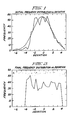
- FIG. 1 The advantages which are achievable with the operation method of the present invention are illustrated for a particular example in Figures 1-3.
- the smooth curve is a standard Gaussian curve normalized to conform to the mean and standard deviation of the data presented.
- the jagged curve shown in Figure 1 depicts the deviation frequency distribution for a set of field measurements. Not only is the Gaussian distribution a good fit for this curve, it also indicates that the jagged curve inherently possesses points of deviation which lie on the tails of the Gaussian distribution. Such deviations are undesirable, particularly since it is one of the objects of the present invention to minimize the maximum error distribution.
- a more desirable distribution is that shown in Figure 2 which is obtained by repeated application of the computational method presented herein.
- Figures 1 and 2 are normalized with respect to the standard deviation.
- Figure 3 illustrates a plot of maximum inhomogeneity as a function of the iteration number. As can be seen, the inhomogeneity falls off relatively rapidly for up to about 100 iterations. Thereafter, improvements occurs more slowly.
- the iterative process may be continued for as long as is desirable, it is generally practical to consider ceasing the iterative steps when the improvement in maximum error amplitude decreases. It is also possible with the present method to measure the field value with currents in place in order to perform the necessary computational steps so as to generate correction values for the coil currents. However the present method has the advantage that only one set of computations need to be computed although more can be if desired. Once desirable values for the currents, l n , are determined, these currents are applied to their respective correction coils.
- the present invention provides an accurate and precise way of operating correction current coils so as to minimize the maximum error occurrence. This is greatly advantageous in constructing magnets having highly uniform magnetic fields, these being particularly advantageous in nuclear magnetic resonance imaging. It is also seen that the method of the present invention can be approximately 30 percent better than the standard least square polynomial approximation method with respect to maximum error.
Landscapes
- Physics & Mathematics (AREA)
- Condensed Matter Physics & Semiconductors (AREA)
- General Physics & Mathematics (AREA)
- Magnetic Resonance Imaging Apparatus (AREA)
Applications Claiming Priority (2)
| Application Number | Priority Date | Filing Date | Title |
|---|---|---|---|
| US06/662,744 US4523166A (en) | 1984-10-19 | 1984-10-19 | Optimal field inhomogeneity correction coil operation for NMR magnets |
| US662744 | 1991-03-01 |
Publications (3)
| Publication Number | Publication Date |
|---|---|
| EP0179370A2 EP0179370A2 (en) | 1986-04-30 |
| EP0179370A3 EP0179370A3 (en) | 1987-10-14 |
| EP0179370B1 true EP0179370B1 (en) | 1990-12-27 |
Family
ID=24659020
Family Applications (1)
| Application Number | Title | Priority Date | Filing Date |
|---|---|---|---|
| EP85112929A Expired EP0179370B1 (en) | 1984-10-19 | 1985-10-11 | Optimal field inhomogeneity correction coil operation for nmr magnets |
Country Status (6)
| Country | Link |
|---|---|
| US (1) | US4523166A (enExample) |
| EP (1) | EP0179370B1 (enExample) |
| JP (1) | JPS6198247A (enExample) |
| CA (1) | CA1218411A (enExample) |
| DE (1) | DE3581166D1 (enExample) |
| IL (1) | IL75479A0 (enExample) |
Families Citing this family (23)
| Publication number | Priority date | Publication date | Assignee | Title |
|---|---|---|---|---|
| US4585992A (en) * | 1984-02-03 | 1986-04-29 | Philips Medical Systems, Inc. | NMR imaging methods |
| IL72388A (en) * | 1984-07-12 | 1988-07-31 | Elscint Ltd | Nmr imaging systems |
| US4680551A (en) * | 1985-10-07 | 1987-07-14 | General Electric Company | Method for homogenizing a static magnetic field over an arbitrary volume |
| JPS62264606A (ja) * | 1986-05-07 | 1987-11-17 | Toshiba Corp | 磁場補正用コイル装置 |
| FR2598808B1 (fr) * | 1986-05-13 | 1993-09-17 | Thomson Cgr | Procede de reglage des correcteurs d'homogeneite du champ magnetique cree par un aimant |
| GB8619012D0 (en) * | 1986-08-04 | 1986-09-17 | Picker Int Ltd | Electromagnet arrangements |
| JPS63109849A (ja) * | 1986-10-29 | 1988-05-14 | 株式会社日立メディコ | Nmrイメ−ジング装置 |
| US4761614A (en) * | 1987-04-27 | 1988-08-02 | Phospho-Energetics, Inc. | Device and method for automatic shimming of NMR instrument |
| US4724412A (en) * | 1987-08-03 | 1988-02-09 | General Electric Company | Method of determining coil arrangement of an actively shielded magnetic resonance magnet |
| JPH03501090A (ja) * | 1987-11-05 | 1991-03-14 | ユニバーシティー オブ クイーンスランド | Nmr分光器の磁界均質化方法 |
| JPH01136645A (ja) * | 1987-11-25 | 1989-05-29 | Toshiba Corp | 磁気共鳴イメージング装置 |
| US4987371A (en) * | 1989-11-27 | 1991-01-22 | General Electric Company | Method for in-vivo shimming |
| US5006804A (en) * | 1989-12-04 | 1991-04-09 | General Electric Company | Method of optimizing shim coil current selection in magnetic resonance magnets |
| DE4210217C2 (de) * | 1992-03-28 | 1994-03-24 | Bruker Analytische Messtechnik | Verfahren zum Bau einer optimierten Magnetspulenanordnung |
| US5343151A (en) * | 1993-03-11 | 1994-08-30 | Bruker Instruments, Inc. | Method for automatically shimming a high resolution NMR magnet |
| DE4333440C1 (de) * | 1993-09-30 | 1995-04-06 | Siemens Ag | Verfahren zur Shimmung eines Magnetfeldes in einem Untersuchungsraum eines Kernspinresonanzgerätes |
| US5410287A (en) * | 1994-04-05 | 1995-04-25 | General Electric Company | Open MRI magnet with uniform magnetic field |
| US5428292A (en) * | 1994-04-29 | 1995-06-27 | General Electric Company | Pancake MRI magnet with modified imaging volume |
| US5448214A (en) * | 1994-06-15 | 1995-09-05 | General Electric Company | Open MRI magnet with superconductive shielding |
| US5677630A (en) * | 1996-10-21 | 1997-10-14 | General Electric Company | Planar superconducting MRI magnet |
| US6064208A (en) * | 1998-04-02 | 2000-05-16 | Picker International, Inc. | Two-peak alignment method of field shimming |
| JP4395556B2 (ja) * | 2004-11-22 | 2010-01-13 | 独立行政法人 宇宙航空研究開発機構 | 磁力支持装置の制御定数自動調整方法 |
| EP3379254B1 (en) | 2017-03-20 | 2021-08-18 | F. Hoffmann-La Roche AG | Secondary solid waste container for solid waste of an analyzer |
Family Cites Families (6)
| Publication number | Priority date | Publication date | Assignee | Title |
|---|---|---|---|---|
| US3419904A (en) * | 1966-05-05 | 1968-12-31 | Varian Associates | Superconductive solenoid having winding segments additionally energized for gradient control |
| US3577067A (en) * | 1966-05-11 | 1971-05-04 | Varian Associates | Persistent mode superconductive orthogonal gradient cancelling coils |
| GB2027208B (en) * | 1978-08-05 | 1982-12-15 | Emi Ltd | Magnetic field correction in nmr apparatus |
| US4284950A (en) * | 1978-08-05 | 1981-08-18 | E M I Limited | Imaging systems |
| DE2840178A1 (de) * | 1978-09-15 | 1980-03-27 | Philips Patentverwaltung | Magnetspulenanordnung zur erzeugung von linearen magnetischen gradientenfeldern |
| JPS60189905A (ja) * | 1984-03-09 | 1985-09-27 | Mitsubishi Electric Corp | 高均一磁界発生装置 |
-
1984
- 1984-10-19 US US06/662,744 patent/US4523166A/en not_active Expired - Fee Related
-
1985
- 1985-06-11 IL IL75479A patent/IL75479A0/xx not_active IP Right Cessation
- 1985-06-20 CA CA000484617A patent/CA1218411A/en not_active Expired
- 1985-07-26 JP JP60164259A patent/JPS6198247A/ja active Granted
- 1985-10-11 DE DE8585112929T patent/DE3581166D1/de not_active Expired - Lifetime
- 1985-10-11 EP EP85112929A patent/EP0179370B1/en not_active Expired
Also Published As
| Publication number | Publication date |
|---|---|
| IL75479A0 (en) | 1985-10-31 |
| US4523166A (en) | 1985-06-11 |
| EP0179370A2 (en) | 1986-04-30 |
| CA1218411A (en) | 1987-02-24 |
| DE3581166D1 (de) | 1991-02-07 |
| JPS6198247A (ja) | 1986-05-16 |
| EP0179370A3 (en) | 1987-10-14 |
| JPH0349256B2 (enExample) | 1991-07-29 |
Similar Documents
| Publication | Publication Date | Title |
|---|---|---|
| EP0179370B1 (en) | Optimal field inhomogeneity correction coil operation for nmr magnets | |
| US5006804A (en) | Method of optimizing shim coil current selection in magnetic resonance magnets | |
| CN102210587B (zh) | 用于确定磁共振系统控制序列的方法和装置 | |
| US7443166B2 (en) | Method and magnetic resonance apparatus for generating a measurement sequence executable by apparatus hardware | |
| US7592812B2 (en) | Magnetic resonance imaging apparatus and static magnetic field correction method | |
| EP0434870A1 (en) | Method and apparatus for automated magnetic field shimming in magnetic resonance spectroscopic imaging | |
| US4987371A (en) | Method for in-vivo shimming | |
| CA2021619A1 (en) | Method of optimizing passive shim placement in magnetic resonance magnets | |
| US4928063A (en) | Automatic eddy current correction | |
| EP2478384A1 (en) | Concurrent optimization of rf power and rf field uniformity in mri | |
| EP1460445B1 (en) | Method of magnetic field controlled shimming | |
| JP2716889B2 (ja) | 磁石の高速補正法 | |
| JP6001784B2 (ja) | 磁場調整支援装置、磁場調整支援方法、mri装置および磁石装置 | |
| US5373239A (en) | Shimming method | |
| EP0560396A2 (en) | Nuclear magnetic resonance imaging with improved image quality and operation efficiency | |
| EP0823641B1 (en) | Method for actively and passively shimming a magnet | |
| US4706027A (en) | Method for correcting phase errors in magnetic resonance imaging data | |
| EP0563647B1 (en) | Method for the construction of an optimized magnet coil | |
| US5506504A (en) | Method and apparatus for conducting a spatially resolving magnetic resonance examination of a test subject | |
| US6897653B2 (en) | MRI method for correcting amplitude of resonance signals | |
| CN117347924A (zh) | 基于信号相位的磁共振射频增益校准方法及其系统 | |
| EP3818387B1 (en) | Mri method for b0-mapping | |
| US5218531A (en) | NMR spectroscopic analyzing method | |
| JPH03215246A (ja) | 鉄シムによるシミング方法 |
Legal Events
| Date | Code | Title | Description |
|---|---|---|---|
| PUAI | Public reference made under article 153(3) epc to a published international application that has entered the european phase |
Free format text: ORIGINAL CODE: 0009012 |
|
| AK | Designated contracting states |
Kind code of ref document: A2 Designated state(s): CH DE FR GB IT LI NL SE |
|
| PUAL | Search report despatched |
Free format text: ORIGINAL CODE: 0009013 |
|
| AK | Designated contracting states |
Kind code of ref document: A3 Designated state(s): CH DE FR GB IT LI NL SE |
|
| 17P | Request for examination filed |
Effective date: 19880318 |
|
| 17Q | First examination report despatched |
Effective date: 19900430 |
|
| GRAA | (expected) grant |
Free format text: ORIGINAL CODE: 0009210 |
|
| AK | Designated contracting states |
Kind code of ref document: B1 Designated state(s): CH DE FR GB IT LI NL SE |
|
| PG25 | Lapsed in a contracting state [announced via postgrant information from national office to epo] |
Ref country code: SE Free format text: THE PATENT HAS BEEN ANNULLED BY A DECISION OF A NATIONAL AUTHORITY Effective date: 19901227 Ref country code: LI Effective date: 19901227 Ref country code: IT Free format text: LAPSE BECAUSE OF FAILURE TO SUBMIT A TRANSLATION OF THE DESCRIPTION OR TO PAY THE FEE WITHIN THE PRESCRIBED TIME-LIMIT;WARNING: LAPSES OF ITALIAN PATENTS WITH EFFECTIVE DATE BEFORE 2007 MAY HAVE OCCURRED AT ANY TIME BEFORE 2007. THE CORRECT EFFECTIVE DATE MAY BE DIFFERENT FROM THE ONE RECORDED. Effective date: 19901227 Ref country code: CH Effective date: 19901227 |
|
| ET | Fr: translation filed | ||
| REF | Corresponds to: |
Ref document number: 3581166 Country of ref document: DE Date of ref document: 19910207 |
|
| REG | Reference to a national code |
Ref country code: CH Ref legal event code: PL |
|
| PGFP | Annual fee paid to national office [announced via postgrant information from national office to epo] |
Ref country code: GB Payment date: 19910925 Year of fee payment: 7 |
|
| PGFP | Annual fee paid to national office [announced via postgrant information from national office to epo] |
Ref country code: FR Payment date: 19911023 Year of fee payment: 7 |
|
| PLBE | No opposition filed within time limit |
Free format text: ORIGINAL CODE: 0009261 |
|
| STAA | Information on the status of an ep patent application or granted ep patent |
Free format text: STATUS: NO OPPOSITION FILED WITHIN TIME LIMIT |
|
| PGFP | Annual fee paid to national office [announced via postgrant information from national office to epo] |
Ref country code: DE Payment date: 19911101 Year of fee payment: 7 |
|
| 26N | No opposition filed | ||
| REG | Reference to a national code |
Ref country code: GB Ref legal event code: 746 |
|
| PG25 | Lapsed in a contracting state [announced via postgrant information from national office to epo] |
Ref country code: GB Effective date: 19921011 |
|
| PGFP | Annual fee paid to national office [announced via postgrant information from national office to epo] |
Ref country code: NL Payment date: 19921031 Year of fee payment: 8 |
|
| REG | Reference to a national code |
Ref country code: FR Ref legal event code: DL |
|
| GBPC | Gb: european patent ceased through non-payment of renewal fee |
Effective date: 19921011 |
|
| PG25 | Lapsed in a contracting state [announced via postgrant information from national office to epo] |
Ref country code: FR Effective date: 19930630 |
|
| PG25 | Lapsed in a contracting state [announced via postgrant information from national office to epo] |
Ref country code: DE Effective date: 19930701 |
|
| REG | Reference to a national code |
Ref country code: FR Ref legal event code: ST |
|
| PG25 | Lapsed in a contracting state [announced via postgrant information from national office to epo] |
Ref country code: NL Effective date: 19940501 |
|
| NLV4 | Nl: lapsed or anulled due to non-payment of the annual fee |