EP0179209A2 - Dispositif automatique de commande pour aéronef en particulier pour hélicoptère - Google Patents
Dispositif automatique de commande pour aéronef en particulier pour hélicoptère Download PDFInfo
- Publication number
- EP0179209A2 EP0179209A2 EP85109650A EP85109650A EP0179209A2 EP 0179209 A2 EP0179209 A2 EP 0179209A2 EP 85109650 A EP85109650 A EP 85109650A EP 85109650 A EP85109650 A EP 85109650A EP 0179209 A2 EP0179209 A2 EP 0179209A2
- Authority
- EP
- European Patent Office
- Prior art keywords
- control
- force
- spring
- summation element
- trim
- Prior art date
- Legal status (The legal status is an assumption and is not a legal conclusion. Google has not performed a legal analysis and makes no representation as to the accuracy of the status listed.)
- Granted
Links
Images

Classifications
-
- G—PHYSICS
- G05—CONTROLLING; REGULATING
- G05D—SYSTEMS FOR CONTROLLING OR REGULATING NON-ELECTRIC VARIABLES
- G05D1/00—Control of position, course or altitude of land, water, air, or space vehicles, e.g. automatic pilot
- G05D1/08—Control of attitude, i.e. control of roll, pitch, or yaw
- G05D1/0808—Control of attitude, i.e. control of roll, pitch, or yaw specially adapted for aircraft
- G05D1/0858—Control of attitude, i.e. control of roll, pitch, or yaw specially adapted for aircraft specially adapted for vertical take-off of aircraft
-
- B—PERFORMING OPERATIONS; TRANSPORTING
- B64—AIRCRAFT; AVIATION; COSMONAUTICS
- B64C—AEROPLANES; HELICOPTERS
- B64C27/00—Rotorcraft; Rotors peculiar thereto
- B64C27/54—Mechanisms for controlling blade adjustment or movement relative to rotor head, e.g. lag-lead movement
- B64C27/58—Transmitting means, e.g. interrelated with initiating means or means acting on blades
-
- G—PHYSICS
- G05—CONTROLLING; REGULATING
- G05D—SYSTEMS FOR CONTROLLING OR REGULATING NON-ELECTRIC VARIABLES
- G05D1/00—Control of position, course or altitude of land, water, air, or space vehicles, e.g. automatic pilot
- G05D1/0055—Control of position, course or altitude of land, water, air, or space vehicles, e.g. automatic pilot with safety arrangements
- G05D1/0061—Control of position, course or altitude of land, water, air, or space vehicles, e.g. automatic pilot with safety arrangements for transition from automatic pilot to manual pilot and vice versa
Definitions
- the invention relates to a device for the automatic elimination of control force errors which occur in aircraft, in particular helicopters, due to disturbing forces acting on the control stick for the elevator or rotor blade setting, with an articulated on the control stick which connects it to the main actuator for the elevator or rotor blade setting Control linkage, a control rod engaging at one end approximately with respect to the control linkage on the control stick, which acts at its other end in a spring box with a pretensioned spring, and a trim motor acting with its trim rod from the other side into the spring box.
- the trim motor provided in this customary construction serves to make the control stick free of force again after input of control movements and occurrence of the new flight state.
- the pilot achieves this by means of a trim switch attached to the control stick, with which he can give the trim motor appropriate control commands, whereupon the latter changes the tension of the spring in the spring box by retracting or extending its trim rod so that the control movement of the control stick is compensated and this is again free of forces.
- unwanted interfering forces can act on the joystick at any time, which are caused by accelerations that occur.
- the unbalanced inertial masses inevitably present in the control linkage lead to disturbing moments or forces which act on the control stick.
- the invention is therefore based on the object of providing a device of the type mentioned at the outset, with which disturbing forces or moments acting on the control stick as a result of inertial forces can be largely compensated for.
- the device designed in accordance with the invention is able to compensate almost completely for inertial forces acting on the control stick. This significantly increases flight safety. Furthermore, the device is characterized by great conceptual simplicity, combined with extremely low outlay in terms of equipment and circuitry. The device is further characterized in that it is possible through a suitable choice of the adjustable amplification factor of the amplifier to make the spring force felt by the pilot of the spring contained in the spring box adaptable to his individual wishes by quasi-electronic change of the spring constant. This will also be clarified below.
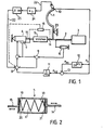
- control stick 1 shows schematically a control stick 1, for example a helicopter, a control linkage 2 articulated on it from the right for the rotor blade adjustment (or elevator adjustment), a control rod 14 acting on the control stick 1 in relation to the control linkage 2, which is in a spring box acts, whose construction principle is shown in Fig.2. Furthermore, a trim motor 4 is shown, the extendable or retractable trim rod 15 of which acts in the spring box 5 from the other side.
- Displacement sensors 6 and 7 measure the control or adjustment path of the control linkage 2 or the trim rod 15. The output signals of these two displacement sensors reach a first summation element 8 in which the output signal of the displacement sensor 7 is subtracted from that of the displacement sensor 6.
- a control force transmitter 10 is attached to the control stick 1 and measures the control force acting on the pilot's hand resting on the handle of the control stick 1.
- Load cells or strain gauges can be used as control force transmitters 10, the former being characterized by significantly lower sensitivity to interference with regard to incident electromagnetic fields, the latter, on the other hand, having to be provided with an appropriate shielding.
- the output signal of the control force transmitter 10 reaches a limiter 12, which adjusts this signal above a predefinable one cuts the limit value.
- the output signal of this limiter is subtracted from that of the control force generator 10 in a downstream, second summation element 13.
- the resulting sum or difference signal arrives at an amplifier 11, the amplification factor of which can be constant or adjustable, and its output signal finally reaches a third summation element 9, where the sum or difference signal of the first summation element 8 is subtracted.
- the resulting sum or difference signal serves as a control signal for the trim motor 4.
- displacement transducers 6 and 7 and the summation element 8 are replaced by a single displacement transducer 16, shown in dashed lines, which measures the difference between the control or adjustment paths of the control rod 14 and the trim rod 15 directly, whereby the resulting output signal is to be fed to the summation element 9.
- a spring 17, or also a spring assembly is inserted between stop surfaces 18, 19, which are at a fixed distance from one another and are structurally connected to the control rod 14.
- the spring 17 is simultaneously between corresponding stop surfaces 20 and 21 of the trim rod 15.
- the trim rod 15 and control rod 14 are axially displaceable relative to one another.
- the distances between the abutment surfaces 18, 19 and 20, 21 from one another are dimensioned such that the spring 17 is constantly under a minimal pretension, by means of which the breakaway force is given to the pilot, ie the force which he must at least exert to make a control movement to effect, which is then in a corresponding compression of the Spring 17 expresses.
- the pilot If the pilot intends to increase the airspeed, he must push the control stick 1 forward. After he has overcome the breakout force, the stick movement begins and at the same time the control rod 14 is moved to the right in FIGS. 1 and 2.
- the spring 17 is compressed because it is carried along by the stop surface 19, but is held by the stop surface 21 associated with the trim rod.
- the pilot can, in the usual way, by means of a trim signal which is emitted via a line 22 shown in FIG. 1, that the trim motor 4 extends its trim rod 15 to the right so far that the spring 17 is open the given prestress is relaxed again, the stop surfaces again having the same relative position to one another as in the trimmed state before the control movement begins or as shown in FIG.
- the control circuit shown in FIG. 1 functions as follows without the occurrence of a malfunction: First, when there is a trimmed state of the control stick 1 corresponding to a virtually zero position, the position sensors 6 and 7 emit signals of equal size which compensate for each other in the summation element 8. If the pilot wants to bring about an increase in the horizontal speed from a trimmed state, he pushes the control stick 1 forward as described above.
- a hand force P H occurs at the location of the control force transmitter 10, which is caused by the location of the pivot point 23 of the control stick 1
- This signal reaches the summation element 9 unchanged via the summation element 8, since the displacement sensor 7 does not detect any change in the adjustment path of the trim rod 15.
- no control signal is output to the trim motor 4 from the summation element 9.
- the pilot must initiate the trimming process himself as described above.
- a corresponding trim signal reaches the summation element 9 via a line 22 and an amplifier 24 and a downstream integrator 25 and from there to the trim motor 4.
- a hand force P H occurs at the location of the control force transmitter 10, which is exactly the same as the spring force P introduced into the spring 17 in the first case due to the disturbance, but now no spring compression occurs because the control stick 1 is held firmly. Therefore, both displacement transducers 6 and 7 do not initially change their output signals, and that of the control force transducer 10 can be fully effective via the amplifier 11 and summation element 9 as a control signal for the trim motor 4, which now causes the spring 17 to be compressed to such an extent that it does Exactly the torque exerted on the joystick 1 and the manual force of the pilot is compensated.
- the control works so quickly and sensitively that the pilot feels no noticeable pressure.
- FIG. 3a shows the dependency of the pilot's manual force P H on the control travel or spring travel d F , which results when he initiates a control movement from a trimmed-out state, which virtually corresponds to a variable zero point.
- the breakout force P A is given by the adjustable mechanical bias of the spring 17. After this breakout force has been overcome, the control path d F can be controlled in the spring 17 in a linear dependence on the manual force P H due to their special design principle (Fig.2) symmetrical in both directions.
- the limiter 12 still shown in FIG. 1 has the following function: it allows low signal values P H , coming from the control force generator 10, to pass unchanged, up to a limiting value P Ae , which is retained as the constant output value of the limiter 12 in the case of further increasing signal values P H is, see Fig.4a. Finally, an output signal P H2 which can be taken off at the output of the summation element 13 is assigned to the signal P H in the manner shown in FIG. 4b.
- the limiting value P Ae can now either be selected to be equal to the mechanical breakout force P A given by the prestressing of the spring 17, or else can be set to another value.
- a signal appears at the output of the summation element 13 as soon as it is reached, which causes the trim motor 4 to react in the sense of an apparent reduction in the breakout force felt by the pilot: It occurs travel immediately, although the mechanical breakout force P A has not yet been reached.
- K Fe K F
- the two compensate each other on the summation element 19 from the displacement sensor 6 and from the control force encoder 10 coming signals from each other.
- K Fe ⁇ K F the gain factor k of the amplifier 11 is increased, the result of the output of the summation element 9 is a resulting control signal for the trim motor 4, which now controls the spring 17 in such a way that the latter is relaxed somewhat, which means that there is an apparently reduced spring stiffness or a reduced control force gradient of the curve P H as a function of the control path d F.
Applications Claiming Priority (2)
| Application Number | Priority Date | Filing Date | Title |
|---|---|---|---|
| DE3431583 | 1984-08-28 | ||
| DE19843431583 DE3431583A1 (de) | 1984-08-28 | 1984-08-28 | Vorrichtung zur automatischen beseitigung von steuerkraftfehlern bei luftfahrzeugen, insbesondere hubschraubern |
Publications (3)
| Publication Number | Publication Date |
|---|---|
| EP0179209A2 true EP0179209A2 (fr) | 1986-04-30 |
| EP0179209A3 EP0179209A3 (en) | 1987-07-22 |
| EP0179209B1 EP0179209B1 (fr) | 1992-04-01 |
Family
ID=6244080
Family Applications (1)
| Application Number | Title | Priority Date | Filing Date |
|---|---|---|---|
| EP85109650A Expired - Lifetime EP0179209B1 (fr) | 1984-08-28 | 1985-07-31 | Dispositif automatique de commande pour aéronef en particulier pour hélicoptère |
Country Status (3)
| Country | Link |
|---|---|
| US (1) | US4607202A (fr) |
| EP (1) | EP0179209B1 (fr) |
| DE (2) | DE3431583A1 (fr) |
Cited By (5)
| Publication number | Priority date | Publication date | Assignee | Title |
|---|---|---|---|---|
| EP0261056A2 (fr) * | 1986-09-18 | 1988-03-23 | United Technologies Corporation | Système de commande collective pour hélicoptère |
| EP0401079A1 (fr) * | 1989-05-31 | 1990-12-05 | Sextant Avionique S.A. | Dispositif de commande électromécanique utilisable pour le pilotage d'un véhicule |
| FR2708112A1 (fr) * | 1993-07-22 | 1995-01-27 | Ratier Figeac Soc | Dispositif de commande à manche de pilotage, notamment mini-manche asservi pour aéronef. |
| WO1995012153A1 (fr) * | 1992-10-06 | 1995-05-04 | Honeywell Inc. | Amortissement de la vitesse dependant de la position dans un dispositif de commande manuel actif |
| EP0718731A1 (fr) * | 1994-12-21 | 1996-06-26 | EUROCOPTER FRANCE, Société Anonyme dite: | Dispositif pour l'actionnement d'un organe commandé pour un aéronef, tel que notamment un hélicoptère, à commandes de vol électriques |
Families Citing this family (26)
| Publication number | Priority date | Publication date | Assignee | Title |
|---|---|---|---|---|
| FR2565882B2 (fr) * | 1984-06-13 | 1987-09-18 | Centre Nat Rech Scient | Dispositif de liaison a plusieurs degres de liberte |
| FR2590044B1 (fr) * | 1985-09-27 | 1988-01-29 | Applic Mach Motrices | Dispositif de commande electrique motorise |
| FR2591189B1 (fr) * | 1985-12-05 | 1988-05-27 | Rabouyt Denis | Dispositif d'assistance au pilotage d'aeronefs a voilure tournante. |
| JPH0226301A (ja) * | 1988-07-12 | 1990-01-29 | Teijin Seiki Co Ltd | サーボ制御装置 |
| US5058825A (en) * | 1989-02-09 | 1991-10-22 | Denis Rabouyt | Steering aid for rotor aircraft |
| US5522568A (en) * | 1993-11-09 | 1996-06-04 | Deka Products Limited Partnership | Position stick with automatic trim control |
| US5489830A (en) * | 1994-09-09 | 1996-02-06 | Mcdonnell Douglas Corporation | Control system with loadfeel and backdrive |
| FR2728536A1 (fr) * | 1994-12-22 | 1996-06-28 | Eurocopter France | Systeme de palonnier a gradient d'effort pour helicoptere |
| FR2728541A1 (fr) * | 1994-12-22 | 1996-06-28 | Eurocopter France | Systeme de manche cyclique a gradient d'effort pour helicoptere |
| JPH0924898A (ja) * | 1995-07-12 | 1997-01-28 | Teijin Seiki Co Ltd | 小型航空機の操縦装置 |
| JP3091743B1 (ja) | 1999-03-30 | 2000-09-25 | 株式会社コミュータヘリコプタ先進技術研究所 | 操縦装置 |
| US6526744B2 (en) | 2001-04-30 | 2003-03-04 | Honeywell International Inc. | System and method for controlling the stowage of jet engine thrust reversers |
| US6519929B2 (en) | 2001-04-30 | 2003-02-18 | Honeywell International, Inc. | System and method for controlling the deployment of jet engine thrust reversers |
| US6439504B1 (en) | 2001-06-15 | 2002-08-27 | Honeywell International, Inc. | System and method for sustaining electric power during a momentary power interruption in an electric thrust reverser actuation system |
| US6681559B2 (en) | 2001-07-24 | 2004-01-27 | Honeywell International, Inc. | Thrust reverser position determination system and method |
| US6684623B2 (en) | 2002-02-27 | 2004-02-03 | Honeywell International, Inc. | Gearless electric thrust reverser actuators and actuation system incorporating same |
| US6622963B1 (en) | 2002-04-16 | 2003-09-23 | Honeywell International Inc. | System and method for controlling the movement of an aircraft engine cowl door |
| US6679458B2 (en) * | 2002-06-10 | 2004-01-20 | The Boeing Company | Split detent tactile cueing vehicle control system |
| FR2847352B1 (fr) * | 2002-11-18 | 2005-01-28 | Airbus France | Systeme de commandes de vol electriques pour aeronef comportant une detection de couplages oscillatoires de pilotage et organe de pilotage pour un tel systeme |
| US7463956B2 (en) | 2003-07-03 | 2008-12-09 | The Boeing Company | Constant vertical state maintaining cueing system |
| CN102001443B (zh) * | 2007-08-08 | 2013-05-29 | 莫戈公司 | 一种复合弹簧 |
| EP2097315B1 (fr) * | 2007-08-08 | 2017-07-26 | Moog Inc. | Levier de commande adapté pour être utilisé dans un système de commandes de vol électriques, et transmission destinée à être utilisée dans celui-ci |
| FR2920744B1 (fr) * | 2007-09-07 | 2010-04-09 | Eurocopter France | Verin de compensation pour commande de vol de giravion |
| FR2943619B1 (fr) * | 2009-03-30 | 2012-08-10 | Sagem Defense Securite | Systeme de commande de vol pour aeronef, comportant une biellette pourvue de capteur |
| FR3034750B1 (fr) * | 2015-04-13 | 2017-12-08 | Airbus Helicopters | Systeme de commande d'un rotor de giravion, giravion equipe d'un tel systeme et methode de commande associee |
| DE102018104192A1 (de) | 2018-02-23 | 2019-08-29 | Autogyro Ag | Tragschrauber |
Citations (4)
| Publication number | Priority date | Publication date | Assignee | Title |
|---|---|---|---|---|
| US3700995A (en) * | 1971-05-20 | 1972-10-24 | United Aircraft Corp | Trim reference for helicopter feel augmentation system |
| FR2377323A1 (fr) * | 1977-01-17 | 1978-08-11 | Sperry Rand Corp | Ensemble de reaction artificielle pour aeronef a servo-commandes |
| GB2022034A (en) * | 1978-06-02 | 1979-12-12 | Sperry Rand Corp | Actuator for aircraft automatic stacilisation systems |
| GB2135796A (en) * | 1983-02-28 | 1984-09-05 | United Technologies Corp | Variable trim-engagement system |
Family Cites Families (4)
| Publication number | Priority date | Publication date | Assignee | Title |
|---|---|---|---|---|
| US3476335A (en) * | 1967-05-19 | 1969-11-04 | Sperry Rand Corp | Pseudo control stick steering system for aircraft having a damper system |
| US3478990A (en) * | 1967-10-31 | 1969-11-18 | Us Navy | Apparatus for resisting control stick deflection |
| US3463423A (en) * | 1968-02-16 | 1969-08-26 | Martin Marietta Corp | Electromechanical force feel system for aircraft control stick |
| US4345195A (en) * | 1979-12-13 | 1982-08-17 | Sperry Corporation | Strapdown multifunction servoactuator apparatus for aircraft |
-
1984
- 1984-08-28 DE DE19843431583 patent/DE3431583A1/de active Granted
-
1985
- 1985-07-31 DE DE8585109650T patent/DE3585770D1/de not_active Expired - Fee Related
- 1985-07-31 EP EP85109650A patent/EP0179209B1/fr not_active Expired - Lifetime
- 1985-08-27 US US06/769,874 patent/US4607202A/en not_active Expired - Fee Related
Patent Citations (4)
| Publication number | Priority date | Publication date | Assignee | Title |
|---|---|---|---|---|
| US3700995A (en) * | 1971-05-20 | 1972-10-24 | United Aircraft Corp | Trim reference for helicopter feel augmentation system |
| FR2377323A1 (fr) * | 1977-01-17 | 1978-08-11 | Sperry Rand Corp | Ensemble de reaction artificielle pour aeronef a servo-commandes |
| GB2022034A (en) * | 1978-06-02 | 1979-12-12 | Sperry Rand Corp | Actuator for aircraft automatic stacilisation systems |
| GB2135796A (en) * | 1983-02-28 | 1984-09-05 | United Technologies Corp | Variable trim-engagement system |
Cited By (10)
| Publication number | Priority date | Publication date | Assignee | Title |
|---|---|---|---|---|
| EP0261056A2 (fr) * | 1986-09-18 | 1988-03-23 | United Technologies Corporation | Système de commande collective pour hélicoptère |
| EP0261056A3 (en) * | 1986-09-18 | 1989-08-30 | United Technologies Corporation | Collective control system for a helicopter |
| EP0401079A1 (fr) * | 1989-05-31 | 1990-12-05 | Sextant Avionique S.A. | Dispositif de commande électromécanique utilisable pour le pilotage d'un véhicule |
| FR2647922A1 (fr) * | 1989-05-31 | 1990-12-07 | Sfena | Dispositif de commande electromecanique utilisable pour le pilotage d'un vehicule |
| WO1995012153A1 (fr) * | 1992-10-06 | 1995-05-04 | Honeywell Inc. | Amortissement de la vitesse dependant de la position dans un dispositif de commande manuel actif |
| FR2708112A1 (fr) * | 1993-07-22 | 1995-01-27 | Ratier Figeac Soc | Dispositif de commande à manche de pilotage, notamment mini-manche asservi pour aéronef. |
| WO1995003566A1 (fr) * | 1993-07-22 | 1995-02-02 | Ratier-Figeac | Dispositif de commande a manche de pilotage, notamment mini-manche asservi pour aeronef |
| US5735490A (en) * | 1993-07-22 | 1998-04-07 | Ratier-Figeac | Control device with a control stick, particularly a servo sidestick for aircraft |
| EP0718731A1 (fr) * | 1994-12-21 | 1996-06-26 | EUROCOPTER FRANCE, Société Anonyme dite: | Dispositif pour l'actionnement d'un organe commandé pour un aéronef, tel que notamment un hélicoptère, à commandes de vol électriques |
| FR2728537A1 (fr) * | 1994-12-21 | 1996-06-28 | Eurocopter France | Dispositif pour l'actionnement d'un organe commande pour un aeronef, tel que notamment un helicoptere, a commandes de vol electriques |
Also Published As
| Publication number | Publication date |
|---|---|
| US4607202A (en) | 1986-08-19 |
| EP0179209A3 (en) | 1987-07-22 |
| EP0179209B1 (fr) | 1992-04-01 |
| DE3431583A1 (de) | 1986-03-13 |
| DE3431583C2 (fr) | 1989-12-21 |
| DE3585770D1 (de) | 1992-05-07 |
Similar Documents
| Publication | Publication Date | Title |
|---|---|---|
| EP0179209B1 (fr) | Dispositif automatique de commande pour aéronef en particulier pour hélicoptère | |
| DE2807902C2 (de) | Steuereinrichtung mit aktiver Kraft rückführung | |
| DE2605407C2 (de) | Regeleinrichtung einer hydraulischen Scheibenbremse | |
| DE2410751C3 (de) | Regler | |
| DE19833189A1 (de) | Lenksystem für ein Fahrzeug | |
| DE3525543A1 (de) | Lenkhilfeeinrichtung fuer kraftfahrzeuge | |
| CH654536A5 (de) | Anordnung zum erzeugen eines fluggeschwindigkeitssignals. | |
| DE3033449C2 (de) | Zweistufiger scherenstromabnehmer | |
| EP0160834B1 (fr) | Dispositif de stabilisation de la force de commande dans un giravion | |
| DE69534317T2 (de) | Schutzsystem gegen überhöhte Geschwindigkeit für Autopilot/Flugbahnregler | |
| DE2601827A1 (de) | Halbautomatisches steuersystem fuer den startvorgang von luftfahrzeugen | |
| DE60008944T2 (de) | Vorrichtung zur Steuerung des Gierwinkels eines Flugzeuges | |
| DE1781220C3 (de) | Flugzeugsteuereinrichtung | |
| EP0175883B1 (fr) | Dispositif pour améliorer la stabilité de commande longitudinale des aéronefs | |
| DE1920384A1 (de) | Steuersystem zur Steuerung von Bewegungen,insbesondere von Flugzeugen | |
| DE2817323A1 (de) | Hubschrauber und verfahren zum steuern desselben in kurven mit querneigung | |
| DE60025235T2 (de) | System zur anpassung der steuerkraftgradienten eines steuerknüppels | |
| DE69817615T2 (de) | VORRICHTUNG UND VERFAHREN ZUR STEUERUNG DER LENKUNGSKRAFT EINES MECHANISCHEN STEUERUNGSSYSTEMS fÜR EIN FLUGZEUG | |
| DE1538558B2 (de) | Redundante elektrische signaluebertragungseinrichtung fuer steuer oder regelkreise | |
| DE2715690A1 (de) | Stabilitaetsverstaerkungsverfahren und -system | |
| DE1481522B2 (de) | Selbstanpassender Flugregler | |
| DE102012112894B4 (de) | Rotorfluggerät mit einer rückkoppelnden Steuereinrichtung zum Generieren von Steuerbefehlen | |
| DE2042429C3 (de) | Lenkeinrichtung für Fahrzeuge mit Ausregelung von StörseitenkrafteinTlüssen | |
| DE2724860C2 (de) | Fahrtanzeigeinstrument für Flugzeuge | |
| DE102014108661B3 (de) | Verfahren zum Steuern eines Fahrzeugs und Steuervorrichtung für ein Fahrzeug zur Anwendung des Verfahrens |
Legal Events
| Date | Code | Title | Description |
|---|---|---|---|
| PUAI | Public reference made under article 153(3) epc to a published international application that has entered the european phase |
Free format text: ORIGINAL CODE: 0009012 |
|
| AK | Designated contracting states |
Kind code of ref document: A2 Designated state(s): DE FR GB IT |
|
| PUAL | Search report despatched |
Free format text: ORIGINAL CODE: 0009013 |
|
| AK | Designated contracting states |
Kind code of ref document: A3 Designated state(s): DE FR GB IT |
|
| 17P | Request for examination filed |
Effective date: 19880114 |
|
| 17Q | First examination report despatched |
Effective date: 19890818 |
|
| GRAA | (expected) grant |
Free format text: ORIGINAL CODE: 0009210 |
|
| AK | Designated contracting states |
Kind code of ref document: B1 Designated state(s): DE FR GB IT |
|
| ET | Fr: translation filed | ||
| REF | Corresponds to: |
Ref document number: 3585770 Country of ref document: DE Date of ref document: 19920507 |
|
| ITF | It: translation for a ep patent filed |
Owner name: STUDIO JAUMANN |
|
| GBT | Gb: translation of ep patent filed (gb section 77(6)(a)/1977) | ||
| PG25 | Lapsed in a contracting state [announced via postgrant information from national office to epo] |
Ref country code: GB Effective date: 19920731 |
|
| RAP2 | Party data changed (patent owner data changed or rights of a patent transferred) |
Owner name: EUROCOPTER DEUTSCHLAND GESELLSCHAFT MIT BESCHRAENK |
|
| PLBE | No opposition filed within time limit |
Free format text: ORIGINAL CODE: 0009261 |
|
| STAA | Information on the status of an ep patent application or granted ep patent |
Free format text: STATUS: NO OPPOSITION FILED WITHIN TIME LIMIT |
|
| 26N | No opposition filed | ||
| GBPC | Gb: european patent ceased through non-payment of renewal fee |
Effective date: 19920731 |
|
| PG25 | Lapsed in a contracting state [announced via postgrant information from national office to epo] |
Ref country code: FR Effective date: 19930331 |
|
| PG25 | Lapsed in a contracting state [announced via postgrant information from national office to epo] |
Ref country code: DE Effective date: 19930401 |
|
| REG | Reference to a national code |
Ref country code: FR Ref legal event code: ST |