EP0179209A2 - Automatic controll device for aircraft, particulary helicopters - Google Patents
Automatic controll device for aircraft, particulary helicopters Download PDFInfo
- Publication number
- EP0179209A2 EP0179209A2 EP85109650A EP85109650A EP0179209A2 EP 0179209 A2 EP0179209 A2 EP 0179209A2 EP 85109650 A EP85109650 A EP 85109650A EP 85109650 A EP85109650 A EP 85109650A EP 0179209 A2 EP0179209 A2 EP 0179209A2
- Authority
- EP
- European Patent Office
- Prior art keywords
- control
- force
- spring
- summation element
- trim
- Prior art date
- Legal status (The legal status is an assumption and is not a legal conclusion. Google has not performed a legal analysis and makes no representation as to the accuracy of the status listed.)
- Granted
Links
Images

Classifications
-
- G—PHYSICS
- G05—CONTROLLING; REGULATING
- G05D—SYSTEMS FOR CONTROLLING OR REGULATING NON-ELECTRIC VARIABLES
- G05D1/00—Control of position, course or altitude of land, water, air, or space vehicles, e.g. automatic pilot
- G05D1/08—Control of attitude, i.e. control of roll, pitch, or yaw
- G05D1/0808—Control of attitude, i.e. control of roll, pitch, or yaw specially adapted for aircraft
- G05D1/0858—Control of attitude, i.e. control of roll, pitch, or yaw specially adapted for aircraft specially adapted for vertical take-off of aircraft
-
- B—PERFORMING OPERATIONS; TRANSPORTING
- B64—AIRCRAFT; AVIATION; COSMONAUTICS
- B64C—AEROPLANES; HELICOPTERS
- B64C27/00—Rotorcraft; Rotors peculiar thereto
- B64C27/54—Mechanisms for controlling blade adjustment or movement relative to rotor head, e.g. lag-lead movement
- B64C27/58—Transmitting means, e.g. interrelated with initiating means or means acting on blades
-
- G—PHYSICS
- G05—CONTROLLING; REGULATING
- G05D—SYSTEMS FOR CONTROLLING OR REGULATING NON-ELECTRIC VARIABLES
- G05D1/00—Control of position, course or altitude of land, water, air, or space vehicles, e.g. automatic pilot
- G05D1/0055—Control of position, course or altitude of land, water, air, or space vehicles, e.g. automatic pilot with safety arrangements
- G05D1/0061—Control of position, course or altitude of land, water, air, or space vehicles, e.g. automatic pilot with safety arrangements for transition from automatic pilot to manual pilot and vice versa
Abstract
Diese Vorrichtung dient zur automatischen Beseitigung von Steuerkraftfehlern, die bei Luftfahrzeugen, insbesondere Hubschraubern, durch am Steuerknüppel 1 für die Höhenruder- bzw. Rotorblatteinstellung angreifende Störkräfte entstehen. Vorhanden sind ein Hauptstellantrieb 3 für die Höhenruder- bzw. Rotorblatteinstellung, ein diesen mit dem Steuerknüppel 1 verbindendes Steuergestänge 2, eine Federbox 5 mit vorgespannter Feder, in die von der einen Seite eine mit dem Steuerknüppel 1 verbundene Steuerstange 14 und von der anderen Seite die Trimmstange 15 eines Trimmotors 4 hineinwirken. Um infolge von Trägheitskräften auf den Steuerknüppel 1 einwirkende Störkräfte möglichst weitgehend zu kompensieren, sind weiterhin vorgesehen zwei Weggeber 6 und 7, ein mit deren Ausgangssignalen beaufschlagtes, erstes Summationsglied 8, ein die Pilotenhandkraft messender Steuerkraftgeber 10, ein Begrenzer 12, ein Verstärker 11 sowie weitere Summationsglieder 13 und 9.This device is used for the automatic elimination of control force errors which occur in aircraft, in particular helicopters, due to disturbing forces acting on the control stick 1 for the elevator or rotor blade setting. There are a main actuator 3 for the elevator or rotor blade setting, a control linkage 2 connecting this to the control stick 1, a spring box 5 with a preloaded spring, into which a control rod 14 connected to the control stick 1 is connected on one side and the control rod 14 on the other side Trim rod 15 of a trim motor 4 act. In order to largely compensate for disturbing forces acting on the joystick 1 as a result of inertial forces, two displacement sensors 6 and 7 are also provided, a first summation element 8 to which their output signals are applied, a pilot force transmitter 10 measuring the pilot hand force, a limiter 12, an amplifier 11 and others Summation terms 13 and 9.
Description
Die Erfindung betrifft eine Vorrichtung zur automatischen Beseitigung von Steuerkraftfehlern, die bei Luftfahrzeugen, insbesondere Hubschraubern, durch am Steuerknüppel für die Höhenruder- bzw. Rotorblatteinstellung angreifende Störkräfte entstehen, mit einem am Steuerknüppel angelenkten, diesen mit dem Hauptstellantrieb für die Höhenruder- bzw. Rotorblatteinstellung verbindenden Steuergestänge, einer mit ihrem einen Ende etwa gegenüber dem Steuergestänge am Steuerknüppel angreifenden Steuerstange, die mit ihrem anderen Ende in eine Federbox mit vorgespannter Feder hineinwirkt, sowie einem mit seiner Trimmstange von der anderen Seite in die Federbox hineinwirkenden Trimmotor.The invention relates to a device for the automatic elimination of control force errors which occur in aircraft, in particular helicopters, due to disturbing forces acting on the control stick for the elevator or rotor blade setting, with an articulated on the control stick which connects it to the main actuator for the elevator or rotor blade setting Control linkage, a control rod engaging at one end approximately with respect to the control linkage on the control stick, which acts at its other end in a spring box with a pretensioned spring, and a trim motor acting with its trim rod from the other side into the spring box.
Der bei dieser üblichen Konstruktion vorgesehene Trimmmotor dient dazu, den Steuerknüppel nach Eingabe von Steuerbewegungen und Eintritt des neuen Flugzustandes wieder kräftefrei zu machen. Dies erreicht der Pilot durch einen am Steuerknüppel angebrachten Trimmschalter, mit dem er dem Trimmotor entsprechende Steuerbefehle geben kann, woraufhin dieser durch Ein- oder Ausfahren seiner Trimmstange die Spannung der Feder in der Federbox so weit verändert, daß die Steuerbewegung des Steuerknüppels kompensiert wird und dieser erneut kräftefrei ist. Es können jedoch jederzeit ungewollte Störkräfte auf den Steuerknüppel einwirken, die durch auftretende Beschleunigungen verursacht werden. In diesem Falle führen die im Steuergestänge unvermeidbar vorhandenen unausgeglichenen trägen Massen zu Störmomenten bzw. -kräften, die auf den Steuerknüppel einwirken.The trim motor provided in this customary construction serves to make the control stick free of force again after input of control movements and occurrence of the new flight state. The pilot achieves this by means of a trim switch attached to the control stick, with which he can give the trim motor appropriate control commands, whereupon the latter changes the tension of the spring in the spring box by retracting or extending its trim rod so that the control movement of the control stick is compensated and this is again free of forces. However, unwanted interfering forces can act on the joystick at any time, which are caused by accelerations that occur. In this case, the unbalanced inertial masses inevitably present in the control linkage lead to disturbing moments or forces which act on the control stick.
Auch dieser selbst ist den Trägheitskräften ausgesetzt, und es hängt von der Massenverteilung der Masse des Steuerknüppels selbst sowie der anderen durch Trägheitskräfte an ihm angreifenden Massen und schließlich von dem Ort des Drehlagerpunktes des Steuerknüppels ab, in welcher Richtung das resultierende Moment auf ihn einwirkt. Derartige.Störkräfte bzw. -momente treten auch dann auf, wenn der Pilot eine bewußte Steuerbewegung veranlaßt, so beispielsweise bei einem aufwärts gerichteten Kurvenflug. Da die auftretenden Störkräfte nicht von vornherein einschätzbar sind, können sie den Piloten verunsichern und ihn bei der einwandfreien Beherrschung des Fluggerätes behindern.This too is exposed to the forces of inertia, and it depends on the mass distribution of the mass of the joystick itself and the other masses acting on it due to inertial forces and finally on the location of the pivot point of the joystick in which direction the resulting moment acts on it. Such disturbing forces or moments also occur when the pilot initiates a conscious control movement, for example during an upward curve flight. Since the disturbing forces that occur cannot be assessed from the outset, they can unsettle the pilot and hinder him in the perfect control of the aircraft.
Der Erfindung liegt daher die Aufgabe zugrunde, eine Vorrichtung der eingangs genannten Art bereitzustellen, mit der infolge von Trägheitskräften auf den Steuerknüppel einwirkende Störkräfte bzw. -momente möglichst weitgehend kompensiert werden können.The invention is therefore based on the object of providing a device of the type mentioned at the outset, with which disturbing forces or moments acting on the control stick as a result of inertial forces can be largely compensated for.
Diese Aufgabe wird gemäß der Erfindung durch folgende Vorrichtungsmerkmale gelöst:This object is achieved according to the invention by the following device features:
- Einen den Steuerweg des Steuergestänges messenden, ersten Weggeber, einen den Stellweg der Trimmstange des Trimmotors messenden, zweiten Weggeber, ein dessen Ausgangssignal von dem des ersten Weggebers subtrahierendes, erstes Summationsglied,A first displacement sensor measuring the control path of the control linkage, a second displacement sensor measuring the adjustment path of the trim rod of the trim motor, a first summation element subtracting its output signal from that of the first displacement sensor,
- einen die Handkraft des Piloten am Steuerknüppel messenden Steuerkraftgeber, einen dessen Ausgangssignal aufnehmenden Begrenzer, ein dessen Ausgangssignal von dem des Steuerkraftgebers subtrahierendes, zweites Summationsglied, einen dessen Summensignal aufnehmenden Verstärker, sowiea control force transmitter measuring the manual force of the pilot on the joystick, a limiter receiving its output signal, a second summation element subtracting its output signal from the control force transmitter, an amplifier receiving its sum signal, and
- ein das Summensignal des ersten Summationsgliedes von dem Ausgangssignal des Verstärkers subtrahierendes, ausgangsseitig ein Ansteuersignal für den Trimmotor lieferndes, drittes Summationsglied.a third summation element subtracting the sum signal of the first summation element from the output signal of the amplifier and on the output side providing a drive signal for the trim motor.
Wie anhand der weiter unten folgenden, detaillierten Beschreibung eines Ausführungsbeispieles deutlich wird, ist die so gemäß der Erfindung ausgestaltete Vorrichtung in der Lage, auf den Steuerknüppel einwirkende Trägheitskräfte nahezu vollständig zu kompensieren. Die Flugsicherheit wird dadurch in erheblichem Maße gesteigert. Weiterhin zeichnet sich die Vorrichtung durch große konzeptionelle Einfachheit aus, verbunden mit äußerst geringem apparativem sowie schaltungstechnischem Aufwand. Die Vorrichtung zeichnet sich weiterhin dadurch aus, daß es durch geeignete Wahl des einstellbaren Verstärkungsfaktors des Verstärkers möglich wird, die für den Piloten fühlbare Federkraft der in der Federbox enthaltenen Feder durch quasi elektronische Veränderung der Federkonstante an dessen individuelle Wünsche anpaßbar zu machen. Auch dies wird weiter unten verdeutlicht werden.As is clear from the detailed description of an exemplary embodiment which follows below, the device designed in accordance with the invention is able to compensate almost completely for inertial forces acting on the control stick. This significantly increases flight safety. Furthermore, the device is characterized by great conceptual simplicity, combined with extremely low outlay in terms of equipment and circuitry. The device is further characterized in that it is possible through a suitable choice of the adjustable amplification factor of the amplifier to make the spring force felt by the pilot of the spring contained in the spring box adaptable to his individual wishes by quasi-electronic change of the spring constant. This will also be clarified below.
Im folgenden wird die Erfindung anhand eines in den Abbildungen schematisch dargestellten Ausführungsbeispieles näher erläutert. Es zeigen:
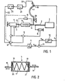
- Fig.1 ein Blockschaltbild einer Vorrichtung gemäß der Erfindung,
- Fig.2 das Prinzip einer bei der Vorrichtung gemäß Fig.1 verwendeten Federbox,
- Fig.3a, 3b zwei Diagramme der Piloten-Handkraft über dem Steuerweg für den ungestörten sowie den gestörten Fall,
- Fig.4a, 4b die Signalverarbeitung durch den Begrenzer sowie das zweite Summationsglied betreffende Diagramme.
- 1 shows a block diagram of a device according to the invention,
- 2 shows the principle of a spring box used in the device according to FIG. 1,
- 3a, 3b two diagrams of the pilot's manual force over the control path for the undisturbed and the disturbed case,
- 4a, 4b the signal processing by the limiter and the diagrams relating to the second summation element.
Fig.1 zeigt in schematischer Weise einen Steuerknüppel 1, beispielsweise eines Hubschraubers, ein an diesem von rechts her angelenktes Steuergestänge 2 für die Rotorblatteinstellung (bzw. die Höhenrudereinstellung), eine am Steuerknüppel 1 gegenüber dem Steuergestänge 2 angreifende Steuerstange 14, welche in eine Federbox hineinwirkt, deren Konstruktionsprinzip in Fig.2 dargestellt ist. Weiterhin ist ein Trimmotor 4 dargestellt, dessen aus- bzw. einfahrbare Trimmstange 15 von der anderen Seite in die Federbox 5 hineinwirkt. Weggeber 6 und 7 messen den Steuer- bzw. Stellweg des Steuergestänges 2 bzw. der Trimmstange 15. Die Ausgangssignale dieser beiden Weggeber gelangen zu einem ersten Summationsglied 8, in dem das Ausgangssignal des Weggebers 7 von dem des Weggebers 6 subtrahiert wird.1 shows schematically a control stick 1, for example a helicopter, a
Am Steuerknüppel 1 ist ein Steuerkraftgeber 10 angebracht, welcher die auf die am Griff des Steuerknüppels 1 anliegende Hand des Piloten wirkende Steuerkraft mißt. Als Steuerkraftgeber 10 können Kraftmeßdosen oder auch Dehnungsmeßstreifen verwendet werden, wobei erstere sich durch wesentlich geringere Störempfindlichkeit hinsichtlich einfallender elektromagnetischer Felder auszeichnet, letztere dagegen mit einer entsprechenden Abschirmung versehen werden müssen. Das Ausgangssignal des Steuerkraftgebers 10 gelangt zu einem Begrenzer 12, der dieses Signal oberhalb eines vorgebbaren, einstellbaren Grenzwertes abschneidet. Das Ausgangssignal dieses Begrenzers wird in einem nachgeordneten, zweiten Summationsglied 13 von dem des Steuerkraftgebers 10 subtrahiert. Das entstehende Summen- bzw. Differenzsignal gelangt zu einem Verstärker 11, dessen Verstärkungsfaktor konstant oder aber einstellbar sein kann, und dessen Ausgangssignal gelangt schließlich zu einem dritten Summationsglied 9, wo das Summen- bzw. Differenzsignal des ersten Summationsgliedes 8 subtrahiert wird. Das hierdurch entstehende Summen- bzw. Differenzsignal dient als Ansteuersignal für den Trimmotor 4.A
Als gleich wirkende Alternative kann vorgesehen sein, daß die Weggeber 6 und 7 sowie das Summationsglied 8 durch einen gestrichelt dargestellten, einzigen Weggeber 16 ersetzt wird, welcher die Differenz zwischen den Steuer- bzw. Stellwegen der Steuerstange 14 sowie der Trimmstange 15 direkt mißt, wobei das entstehende Ausgangssignal dem Summationsglied 9 zuzuführen ist.As an equivalent alternative, it can be provided that the
Die Funktionsweise der Federbox sei anhand der in Fig.2 wiedergegebenen Prinzipskizze erläutert. Eine Feder 17, oder auch ein Federpaket, ist zwischen Anschlagflächen 18, 19 eingelegt, die einen festen Abstand zueinander haben und konstruktiv fest mit der Steuerstange 14 verbunden sind. Die Feder 17 liegt gleichzeitig zwischen entsprechenden Anschlagflächen 20 und 21 der Trimmstange 15. Trimmstange 15 und Steuerstange 14 sind relativ zueinander axial verschiebbar. Die Abstände der Anschlagflächen 18, 19 sowie 20, 21 voneinander sind so bemessen, daß die Feder 17 ständig unter einer minimalen Vorspannung steht, durch welche die Ausbrechkraft für den Piloten gegeben ist, d.h. die Kraft, die er mindestens aufbringen muß, um eine Steuerbewegung zu bewirken, die sich dann in einer entsprechenden Stauchung der Feder 17 äußert. Wird nämlich vom Piloten eine Fluggeschwindigkeitserhöhung beabsichtigt, so muß er den Steuerknüppel 1 nach vorn drücken. Nachdem er die Ausbrechkraft überwunden hat, setzt die Knüppelbewegung ein, und gleichzeitig wird die Steuerstange 14 in Fig. 1 bzw. 2 nach rechts bewegt. Die Feder 17 wird gestaucht, da sie von der Anschlagfläche 19 mitgenommen, von der der Trimmstange zugehörigen Anschlagfläche 21 jedoch festgehalten wird. Nach Erreichen einer neuen stabilen Fluglage kann der Pilot durch ein Trimmsignal, das über eine in Fig.1 dargestellte Leitung 22 abgegeben wird, in üblicher Weise bewirken, daß der Trimmotor 4 seine Trimmstange 15 so weit nach rechts ausfährt, daß die Feder 17 bis auf die gegebene Vorspannung wieder entspannt wird, wobei die Anschlagflächen wieder dieselbe relative Lage zueinander haben wie im ausgetrimmten Zustand vor Einsetzen der Steuerbewegung bzw. wie in Fig.2 dargestellt.The functioning of the spring box will be explained with reference to the schematic diagram shown in Fig.2. A
Die in Fig.1 gezeigte Regelschaltung funktioniert ohne Auftreten einer Störung wie folgt: Zunächst geben die Weggeber 6 und 7 bei Vorliegen eines quasi einer Nulllage entsprechenden ausgetrimmten Zustandes des Steuerknüppels 1 gleichgroße Signale ab, die sich im Summationsglied 8 zu Null kompensieren. Will der Pilot aus einem ausgetrimmten Zustand etwa eine Erhöhung der Horizontalgeschwindigkeit bewirken, so drückt er wie oben beschrieben den Steuerknüppel 1 nach vorn. Der Weggeber 6 mißt eine Steuerwegveränderung dF, die mit dem Federweg der Feder 17 identisch ist: dF = PF/KF, wobei PF die von der Steuerstange 14 in die Feder eingeleitete Federkraft,KF die mechanische Federkonstante ist. Gleichzeitig tritt am Ort des Steuerkraftgebers 10 eine Handkraft PH auf, die über das durch den Ort des Drehlagerpunktes 23 des Steuerknüppels 1 bedingte Hebelverhältnis a/b zur Federkraft P proportional ist: P F = (a/b)-PH. Ein dieser Handkraft PH entsprechendes Ausgangssignal des Steuerkraftgebers 10 gelangt über das Summationsglied 13 zum Verstärker 11. Dort kann es mit einem Verstärkungsfaktor k = 1/KFe multipliziert werden, so daß ein Signal PH/KFe zum Summationsglied 9 gelangt.The control circuit shown in FIG. 1 functions as follows without the occurrence of a malfunction: First, when there is a trimmed state of the control stick 1 corresponding to a virtually zero position, the
Das währenddessen vom Weggeber 6 abgegebene Ausgangssignal entspricht dem Federweg dF = PF/KF. Dieses Signal gelangt über das Summationsglied 8 unverändert zum Summationsglied 9, da der Weggeber 7 keine Änderung des Stellweges der Trimmstange 15 feststellt. Wird nun der Steuerkraftgeber 10 entsprechend geeicht, so kann der Proportionalitätsfaktor a/b zu 1 gemacht werden, so daß die Eingangssignale für das Summationsglied 9 im vorliegenden Falle einander gleich sind, wenn im Verstärkungsfaktor k der Nenner KFe = K, gewählt wird: d F = PF/KF. Somit wird kein Ansteuersignal an den Trimmmotor 4 vom Summationsglied 9 abgegeben. Der Pilot muß wie oben beschrieben den Austrimmvorgang selbst einleiten. Hierzu gelangt ein entsprechendes Trimmsignal über eine Leitung 22 sowie einen Verstärker 24 sowie einen nachgeschalteten Integrator 25 zum Summationsglied 9 und von dort zum Trimmotor 4.The output signal emitted by the
Tritt nun als Störung eine Beschleunigung, beispielsweise infolge einer von vorn einfallenden Windbö, auf, so wirken vom Steuergestänge 2 her Trägheitskräfte auf das untere Ende des Steuerknüppels 1 ein. Diese haben ihre Ursache darin, daß das Steuergestänge mit Massen behaftet ist. Der in bezug auf den Drehlagerpunkt 23 obere Teil des Steuerknüppels 1 ist ebenfalls einer nach vorn wirkenden Trägheitsbeschleunigung ausgesetzt. Falls das hierdurch ausgeübte Drehmoment dasjenige von den zuvor genannten Kräften ausgeübte nicht übersteigt, ergibt sich ein resultierendes Drehmoment, welches das untere Ende des Steuerknüppels 1 in Fig.1 nach links zu bewegen sucht.If acceleration occurs as a disturbance, for example as a result of a gust of wind coming in from the front, inertial forces act on the lower end of the control stick 1 from the
Der Pilot kann nun auf zweierlei Weise reagieren: Er kann theoretisch, was allerdings in der Praxis kaum der Fall sein wird, dem nach hinten (in Fig.1 nach rechts) drückenden Griff des Steuerknüppels 1 nachgeben oder aber, was zur Aufrechterhaltung der Fluglage erforderlich wäre, ihn durch entgegengerichteten Handdruck an einer Bewegung hindern.The pilot can now react in two ways: theoretically, which, however, will hardly be the case in practice, give in to the handle of the control stick 1 pushing backwards (to the right in Fig. 1) or what is required to maintain the attitude would be to prevent him from moving by hand pressure.
Im ersteren Falle erfolgt nach Überwindung der Ausbrechkraft, die gerade wegen derartiger Störungen nicht zu klein bemessen werden soll, eine Stauchung der Feder 17 in der Federbox 5, verbunden mit einem Federweg dF = PF/KF. Gleichzeitig ändert sich das Ausgangssignal des Weggebers 6 um einen diesem Federweg entsprechenden Betrag. Der Steuerkraftgeber 10 jedoch wird kein Ausgangssignal abgeben, da keine Spannungen in den Steuerknüppel 1 eingeleitet werden. Der Weggeber 7 ändert sein Ausgangssignal nicht. Daher kann die Änderung des Ausgangssignals des Weggebers 6 über beide Summationsglieder voll als Ansteuersignal an den Trimmotor 4 gelangen, der nun eine Entspannung der Feder 17 um eben den Steuerweg d. bewirkt, so daß der Steuerknüppel 1 wieder kräftefrei ist.In the former case, after overcoming the breakout force, which should not be dimensioned too small precisely because of such disturbances, the
Hier ist zu beachten, daß die Regelung im Vergleich zu den auftretenden Störungen sehr schnell wirkt, da der gesamte Hubschrauber natürlich eine beachtliche Gesamtmasse besitzt und die Verzögerung durch eine Windbö daher nur relativ langsam eintritt. Es werden daher keine großen Federwege dF auftreten, vielmehr wird die Korrektur durch den Trimmotor 4 sehr schnell folgen.It should be noted here that the control works very quickly in comparison to the faults that occur, since the entire helicopter naturally has a considerable overall mass and the deceleration due to a gust of wind therefore occurs relatively slowly. There will therefore be no large spring travel d F , rather the correction by the trim motor 4 will follow very quickly.
Im zweiten Falle tritt am Ort des Steuerkraftgebers 10 eine Handkraft PH auf, die genau der im ersten Falle durch die Störung in die Feder 17 eingebrachten Federkraft P gleicht, wobei nun jedoch keine Federstauchung eintritt, da der Steuerknüppel 1 festgehalten wird. Daher ändern beide Weggeber 6 und 7 ihre Ausgangssignale zunächst nicht, und dasjenige des Steuerkraftgebers 10 kann über Verstärker 11 und Summationsglied 9 voll als Ansteuersignal für den Trimmotor 4 wirksam werden, welcher nun eine Stauchung der Feder 17 in einem solchen Maße bewirkt, daß das auf den Steuerknüppel 1 ausgeübte Drehmoment genau aufgehoben und die Handkraft des Piloten kompensiert wird. Auch hier arbeitet die Regelung so schnell und feinfühlig, daß der Pilot gar keinen merklichen Druck verspürt.In the second case, a hand force P H occurs at the location of the
In beiden geschilderten Fällen wird eine entscheidende Verbesserung der Flugstabilität als Resultat der erfindungsgemäßen Maßnahmen auf.In both of the cases described, a decisive improvement in flight stability is the result of the measures according to the invention.
Natürlich können auch Überlagerungen von bewußten Steuerbewegungen und Störungen des erwähnten Typs vorkommen. Auch dann ergibt sich aus der Überlagerung der geschilderten Regelvorgänge der erwünschte stabilisierende Effekt.Of course, there can also be overlaps of conscious control movements and disturbances of the type mentioned. Even then, the desired stabilizing effect results from the superimposition of the control processes described.
In Fig.3a ist die Abhängigkeit der Handkraft PH des Piloten von dem Steuerweg bzw. Federweg dF dargestellt, der sich ergibt, wenn er aus einem ausgetrimmten Zustand, der quasi einem variablen Nullpunkt entspricht, heraus eine Steuerbewegung einleitet. Die Ausbrechkraft PA ist durch die einstellbare mechanische Vorspannung der Feder 17 gegeben. Nach Überwindung dieser Ausbrechkraft ist der Steuerweg dF in linearer Abhängigkeit von der Handkraft PH in die Feder 17 einsteuerbar, und zwar aufgrund von deren besonderem Konstruktionsprinzip (Fig.2) in beiden Richtungen symmetrisch.3a shows the dependency of the pilot's manual force P H on the control travel or spring travel d F , which results when he initiates a control movement from a trimmed-out state, which virtually corresponds to a variable zero point. The breakout force P A is given by the adjustable mechanical bias of the
Fig.3b zeigt, wie sich das obige Diagramm bei Auftreten einer Störkraft PSt, die genau der Ausbrechkraft PA entspricht, verändert: Die Kurve wird um den Betrag dieser Störkraft PSt = PA in Richtung der Ordinate versetzt. Dies bedeutet, daß der Pilot, falls er in diesem Moment eine Steuerbewegung einleitet, in der einen Richtung gar keine und in der anderen Richtung eine verdoppelte Ausbrechkraft vorfindet. In der einen Richtung würde seine Steuerbewegung sofort in einen entsprechenden Federweg dF umgesetzt werden, in der anderen Richtung müsste zunächst die doppelte Ausbrechkraft 2PA überwunden werden.3b shows how the above diagram changes when an interference force P St that exactly corresponds to the breakout force P A occurs : the curve is offset by the amount of this interference force P St = P A in the direction of the ordinate. This means that if the pilot initiates a control movement at this moment, there is no breakout force in one direction and a doubled breakout force in the other direction. In one direction its control movement would immediately be converted into a corresponding spring travel d F , in the other direction the double breakout force 2P A would first have to be overcome.
Der in Fig.1 noch dargestellte Begrenzer 12 hat folgende Funktion: Er läßt niedrige Signalwerte PH, vom Steuerkraftgeber 10 her kommend, unverändert passieren, bis zu einem Begrenzungswert PAe, der bei weiter ansteigenden Signalwerten PH als konstanter Ausgangswert des Begrenzers 12 beibehalten wird, siehe Fig.4a. Schließlich ist ein am Ausgang des Summationsgliedes 13 abnehmbares Ausgangssignal PH2 dem Signal PH auf die in Fig.4b wiedergegebene Weise zugeordnet. Der Begrenzungswert PAe kann nun entweder gleich der durch die Vorspannung der Feder 17 gegebenen mechanischen Ausbrechkraft PA gewählt oder aber auf einen anderen Wert eingestellt werden.The
Zunächst sei erläutert, wie die Regelschaltung mit dem Begrenzer 12 bei Einleiten einer normalen Steuerbewegung des Piloten reagiert. Er möge auf den Steuerknüppel 1 einen nach vorn gerichteten Druck im Sinne einer gewünschten Fluggeschwindigkeitserhöhung ausüben. Solange die Ausbrechkraft PA, gegeben durch die mechanische Vorspannung der Feder 17, noch nicht überschritten ist, tritt weder ein Steuer- noch ein Federweg d auf, das Ausgangssignal des Weggebers 6 bleibt unverändert. Allerdings mißt der Steuerkraftgeber 10 eine Handkraft PH<PA, das entsprechende Ausgangssignal kann jedoch das Summationsglied 13 noch nicht passieren, und zwar wegen der Begrenzercharakteristik (Fig.4). Erreicht die Handkraft PH des Piloten nun den Begrenzungswert PAe des Begrenzers 12, der zunächst gleich der mechanischen Ausbrechkraft PA sein möge, so tritt einerseits ein Federweg dF und ein entsprechendes Ausgangssignal des Weggebers 6 und andererseits am Ausgang des Summationsgliedes 13 ein ebenso großes, nämlich den Federweg repräsentierendes Signal auf. Beide kompensieren sich im Summationsglied 9, so daß kein Ansteuersignal zum Trimmmotor 4 gelangt. Der Pilot findet also ein ganz normales Verhalten vor und muß selbst austrimmen.First, it will be explained how the control circuit with the
Wird der Begrenzungswert PAe kleiner eingestellt als die mechanische Ausbrechkraft PA, so erscheint am Ausgang des Summationsgliedes 13 schon von deren Erreichen ein Signal, welches den Trimmotor 4 zu einer Reaktion im Sinne einer scheinbaren Verminderung der für den Piloten spürbaren Ausbrechkraft veranlaßt: Es tritt sofort ein Federweg auf, obwohl die mechanische Ausbrechkraft PA noch nicht erreicht ist. Durch Einstellung des Begrenzungswertes PAe ist demnach eine Veränderung der für den Piloten spürbaren Ausbrechkraft individuell erreichbar.If the limiting value P Ae is set smaller than the mechanical breakout force P A , a signal appears at the output of the
Tritt nun aus einem ausgetrimmten Zustand des Steuerknüppels 1 eine kleine, noch unterhalb der mechanischen Ausbrechkraft PA liegende Störkraft auf, so hat dies zunächst keinerlei Folgen, da die Störkraft voll von der vorgespannten Feder 17 aufgenommen wird, ohne daß jedoch ein Federweg bzw. ein Steuerweg der Steuerstange 14 auftritt. Somit bleibt der Steuerknüppel 1 in Ruhe und weder am Weggeber 6 noch am Steuerkraftgeber 10 treten Ausgangssignale auf. Überschreitet die Störkraft die mechanische Ausbrechkraft PA, so spürt der Pilot eine Handkraft PHI sobald er den Steuerknüppel 1 festhält, der sonst der Störkraft nachgeben würde. Das nun vom Steuerkraftgeber 10 abgegebene Ausgangssignal wird zunächst am Summationsglied 13 blockiert, und auch der Weggeber 6 verändert sein Ausgangssignal nicht. Der Pilot hat nun das Empfinden, als wenn er selbst eine kleine, noch unterhalb der Ausbrechkraft PA liegende Fühlbewegung am Steuerknüppel 1 durchführen würde, die jedoch zu keiner Änderung der Fluglage führt. Erst wenn das Ausgangssignal PH des Steuerkraftgebers 10 den Wert PA (im Falle PAe = PA) erreicht, gelangt vom Ausgang des Summationsgliedes 13 ein Ansteuersignal an den Trimmmotor 4, welcher nunmehr durch entsprechende Reaktion die ggfs. weiter ansteigenden Störkräfte kompensiert.If a small, still below the mechanical breakout force P A occurs from a trimmed state of the joystick 1, this initially has no consequences, since the interference force is fully absorbed by the
Durch Einstellung des Verstärkungsfaktors k = 1/KFe des Verstärkers 11 ist es möglich, dem Piloten eine individuell wählbare Federsteifigkeit der Feder 17, die von der mechanischen Federkonstante KF abweicht, vorzugeben. Dies sei für den Fall verdeutlicht, daß der Pilot eine Steuerbewegung im Sinne einer Fluggeschwindigkeitserhöhung einleitet. Nach Überwindung der Ausbrechkraft PA der Feder 17 steht, wie oben bereits geschildert, am Ausgang des Weggebers 6 eine dem nun resultierenden Federweg dF entsprechende Änderung des Ausgangssignals an. Auch am Ausgang des Summationsgliedes 13 tritt ein Signal auf - es sei angenommen, daß PAe = PA - welches nach Multiplikation mit dem Verstärkungsfaktor k des Verstärkers 11 an das Summationsglied 9 gelangt. Ist nun KFe = KF, so kompensieren sich die beiden am Summationsglied 19 vom Weggeber 6 und vom Steuerkraftgeber 10 her ankommenden Signale gegenseitig. Wird jedoch KFe< KF eingestellt, der Verstärkungsfaktor k des Verstärkers 11 also vergrößert, so ergibt sich am Ausgang des Summationsgliedes 9 ein resultierendes Ansteuersignal für den Trimmotor 4, welcher nun so in die Feder 17 steuert, daß diese etwas entspannt wird, wodurch sich eine scheinbar verkleinerte Federsteifigkeit bzw. ein verkleinerter Steuerkraftgradient der Kurve PH in Abhängigkeit vom Steuerweg dF ergibt. Umgekehrt ergibt sich für KFe> KF, d.h. für eine Verkleinerung des Verstärkungsfaktors k, durch entsprechende Reaktion des Trimmotors 4 eine scheinbare Erhöhung der Federsteifigkeit der Feder 17. Dies bedeutet eine Veränderung der Steigung der in Fig.3a gegebenen Kurve, ausgehend von einer Parallelen zur Abszisse für den Fall KFe = 0 und mit zunehmender Steigung bei zunehmendem KFe0 wobei sich alle diese dem veränderlichen, einstellbaren Parameter KFe entsprechenden Geraden im Punkt PH = PA auf der Ordinate schneiden.By setting the gain factor k = 1 / K Fe of the
Claims (6)
Applications Claiming Priority (2)
| Application Number | Priority Date | Filing Date | Title |
|---|---|---|---|
| DE3431583 | 1984-08-28 | ||
| DE19843431583 DE3431583A1 (en) | 1984-08-28 | 1984-08-28 | DEVICE FOR THE AUTOMATIC ELIMINATION OF TAX FORCE ERRORS IN AIRCRAFT, IN PARTICULAR HELICOPTERS |
Publications (3)
| Publication Number | Publication Date |
|---|---|
| EP0179209A2 true EP0179209A2 (en) | 1986-04-30 |
| EP0179209A3 EP0179209A3 (en) | 1987-07-22 |
| EP0179209B1 EP0179209B1 (en) | 1992-04-01 |
Family
ID=6244080
Family Applications (1)
| Application Number | Title | Priority Date | Filing Date |
|---|---|---|---|
| EP85109650A Expired - Lifetime EP0179209B1 (en) | 1984-08-28 | 1985-07-31 | Automatic controll device for aircraft, particulary helicopters |
Country Status (3)
| Country | Link |
|---|---|
| US (1) | US4607202A (en) |
| EP (1) | EP0179209B1 (en) |
| DE (2) | DE3431583A1 (en) |
Cited By (5)
| Publication number | Priority date | Publication date | Assignee | Title |
|---|---|---|---|---|
| EP0261056A2 (en) * | 1986-09-18 | 1988-03-23 | United Technologies Corporation | Collective control system for a helicopter |
| EP0401079A1 (en) * | 1989-05-31 | 1990-12-05 | Sextant Avionique S.A. | Electromechanical control device usable for piloting a vehicle |
| FR2708112A1 (en) * | 1993-07-22 | 1995-01-27 | Ratier Figeac Soc | Control device with a control stick, in particular a slave mini-handle for an aircraft. |
| WO1995012153A1 (en) * | 1992-10-06 | 1995-05-04 | Honeywell Inc. | Position dependent rate dampening in an active hand controller |
| EP0718731A1 (en) * | 1994-12-21 | 1996-06-26 | EUROCOPTER FRANCE, Société Anonyme dite: | Arrangement for actuating a controlled element for an aircraft, especially a helicopter, with electrical flight control system |
Families Citing this family (26)
| Publication number | Priority date | Publication date | Assignee | Title |
|---|---|---|---|---|
| FR2565882B2 (en) * | 1984-06-13 | 1987-09-18 | Centre Nat Rech Scient | CONNECTION DEVICE WITH MULTIPLE DEGREES OF FREEDOM |
| FR2590044B1 (en) * | 1985-09-27 | 1988-01-29 | Applic Mach Motrices | MOTORIZED ELECTRICAL CONTROL DEVICE |
| FR2591189B1 (en) * | 1985-12-05 | 1988-05-27 | Rabouyt Denis | DEVICE FOR ASSISTING THE PILOTAGE OF TURNED AIRCRAFT. |
| JPH0226301A (en) * | 1988-07-12 | 1990-01-29 | Teijin Seiki Co Ltd | Servocontroller |
| US5058825A (en) * | 1989-02-09 | 1991-10-22 | Denis Rabouyt | Steering aid for rotor aircraft |
| US5522568A (en) * | 1993-11-09 | 1996-06-04 | Deka Products Limited Partnership | Position stick with automatic trim control |
| US5489830A (en) * | 1994-09-09 | 1996-02-06 | Mcdonnell Douglas Corporation | Control system with loadfeel and backdrive |
| FR2728541A1 (en) * | 1994-12-22 | 1996-06-28 | Eurocopter France | CYCLIC SLEEVE SYSTEM WITH GRADIENT FOR HELICOPTER |
| FR2728536A1 (en) * | 1994-12-22 | 1996-06-28 | Eurocopter France | PALIERIER SYSTEM WITH GRADIENT OF EFFORT FOR HELICOPTER |
| JPH0924898A (en) * | 1995-07-12 | 1997-01-28 | Teijin Seiki Co Ltd | Steering device for small aircraft |
| JP3091743B1 (en) | 1999-03-30 | 2000-09-25 | 株式会社コミュータヘリコプタ先進技術研究所 | Pilot device |
| US6526744B2 (en) | 2001-04-30 | 2003-03-04 | Honeywell International Inc. | System and method for controlling the stowage of jet engine thrust reversers |
| US6519929B2 (en) | 2001-04-30 | 2003-02-18 | Honeywell International, Inc. | System and method for controlling the deployment of jet engine thrust reversers |
| US6439504B1 (en) | 2001-06-15 | 2002-08-27 | Honeywell International, Inc. | System and method for sustaining electric power during a momentary power interruption in an electric thrust reverser actuation system |
| US6681559B2 (en) | 2001-07-24 | 2004-01-27 | Honeywell International, Inc. | Thrust reverser position determination system and method |
| US6684623B2 (en) | 2002-02-27 | 2004-02-03 | Honeywell International, Inc. | Gearless electric thrust reverser actuators and actuation system incorporating same |
| US6622963B1 (en) | 2002-04-16 | 2003-09-23 | Honeywell International Inc. | System and method for controlling the movement of an aircraft engine cowl door |
| US6679458B2 (en) * | 2002-06-10 | 2004-01-20 | The Boeing Company | Split detent tactile cueing vehicle control system |
| FR2847352B1 (en) * | 2002-11-18 | 2005-01-28 | Airbus France | AIRCRAFT FLIGHT CONTROL SYSTEM FOR AIRCRAFT HAVING DETECTION OF OSCILLATORY STEERING COUPLINGS AND STEERING BODY FOR SUCH A SYSTEM |
| US7463956B2 (en) | 2003-07-03 | 2008-12-09 | The Boeing Company | Constant vertical state maintaining cueing system |
| JP5309138B2 (en) * | 2007-08-08 | 2013-10-09 | ムーグ インコーポレーテッド | Control stick suitable for use in fly-by-wire flight control system and connecting mechanism used therefor |
| CN102001443B (en) * | 2007-08-08 | 2013-05-29 | 莫戈公司 | Composite spring |
| FR2920744B1 (en) * | 2007-09-07 | 2010-04-09 | Eurocopter France | COMPENSATION JACK FOR FLIGHT CONTROL |
| FR2943619B1 (en) * | 2009-03-30 | 2012-08-10 | Sagem Defense Securite | FLIGHT CONTROL SYSTEM FOR AIRCRAFT, COMPRISING A LINK PROVIDED WITH A SENSOR |
| FR3034750B1 (en) * | 2015-04-13 | 2017-12-08 | Airbus Helicopters | SYSTEM FOR CONTROLLING A ROTOR OF GIRAVION, GIRAVION EQUIPPED WITH SUCH A SYSTEM AND METHOD OF CONTROLLING THE SAME |
| DE102018104192A1 (en) | 2018-02-23 | 2019-08-29 | Autogyro Ag | gyrocopter |
Citations (4)
| Publication number | Priority date | Publication date | Assignee | Title |
|---|---|---|---|---|
| US3700995A (en) * | 1971-05-20 | 1972-10-24 | United Aircraft Corp | Trim reference for helicopter feel augmentation system |
| FR2377323A1 (en) * | 1977-01-17 | 1978-08-11 | Sperry Rand Corp | ARTIFICIAL REACTION KIT FOR SERVO-CONTROLLED AIRCRAFT |
| GB2022034A (en) * | 1978-06-02 | 1979-12-12 | Sperry Rand Corp | Actuator for aircraft automatic stacilisation systems |
| GB2135796A (en) * | 1983-02-28 | 1984-09-05 | United Technologies Corp | Variable trim-engagement system |
Family Cites Families (4)
| Publication number | Priority date | Publication date | Assignee | Title |
|---|---|---|---|---|
| US3476335A (en) * | 1967-05-19 | 1969-11-04 | Sperry Rand Corp | Pseudo control stick steering system for aircraft having a damper system |
| US3478990A (en) * | 1967-10-31 | 1969-11-18 | Us Navy | Apparatus for resisting control stick deflection |
| US3463423A (en) * | 1968-02-16 | 1969-08-26 | Martin Marietta Corp | Electromechanical force feel system for aircraft control stick |
| US4345195A (en) * | 1979-12-13 | 1982-08-17 | Sperry Corporation | Strapdown multifunction servoactuator apparatus for aircraft |
-
1984
- 1984-08-28 DE DE19843431583 patent/DE3431583A1/en active Granted
-
1985
- 1985-07-31 EP EP85109650A patent/EP0179209B1/en not_active Expired - Lifetime
- 1985-07-31 DE DE8585109650T patent/DE3585770D1/en not_active Expired - Fee Related
- 1985-08-27 US US06/769,874 patent/US4607202A/en not_active Expired - Fee Related
Patent Citations (4)
| Publication number | Priority date | Publication date | Assignee | Title |
|---|---|---|---|---|
| US3700995A (en) * | 1971-05-20 | 1972-10-24 | United Aircraft Corp | Trim reference for helicopter feel augmentation system |
| FR2377323A1 (en) * | 1977-01-17 | 1978-08-11 | Sperry Rand Corp | ARTIFICIAL REACTION KIT FOR SERVO-CONTROLLED AIRCRAFT |
| GB2022034A (en) * | 1978-06-02 | 1979-12-12 | Sperry Rand Corp | Actuator for aircraft automatic stacilisation systems |
| GB2135796A (en) * | 1983-02-28 | 1984-09-05 | United Technologies Corp | Variable trim-engagement system |
Cited By (10)
| Publication number | Priority date | Publication date | Assignee | Title |
|---|---|---|---|---|
| EP0261056A2 (en) * | 1986-09-18 | 1988-03-23 | United Technologies Corporation | Collective control system for a helicopter |
| EP0261056A3 (en) * | 1986-09-18 | 1989-08-30 | United Technologies Corporation | Collective control system for a helicopter |
| EP0401079A1 (en) * | 1989-05-31 | 1990-12-05 | Sextant Avionique S.A. | Electromechanical control device usable for piloting a vehicle |
| FR2647922A1 (en) * | 1989-05-31 | 1990-12-07 | Sfena | ELECTROMECHANICAL CONTROL DEVICE USED FOR STEERING A VEHICLE |
| WO1995012153A1 (en) * | 1992-10-06 | 1995-05-04 | Honeywell Inc. | Position dependent rate dampening in an active hand controller |
| FR2708112A1 (en) * | 1993-07-22 | 1995-01-27 | Ratier Figeac Soc | Control device with a control stick, in particular a slave mini-handle for an aircraft. |
| WO1995003566A1 (en) * | 1993-07-22 | 1995-02-02 | Ratier-Figeac | Control device with a control stick, particularly a servo sidestick for aircraft |
| US5735490A (en) * | 1993-07-22 | 1998-04-07 | Ratier-Figeac | Control device with a control stick, particularly a servo sidestick for aircraft |
| EP0718731A1 (en) * | 1994-12-21 | 1996-06-26 | EUROCOPTER FRANCE, Société Anonyme dite: | Arrangement for actuating a controlled element for an aircraft, especially a helicopter, with electrical flight control system |
| FR2728537A1 (en) * | 1994-12-21 | 1996-06-28 | Eurocopter France | DEVICE FOR ACTUATING A CONTROL MEMBER FOR AN AIRCRAFT, IN PARTICULAR A HELICOPTER, WITH ELECTRIC FLIGHT CONTROLS |
Also Published As
| Publication number | Publication date |
|---|---|
| EP0179209A3 (en) | 1987-07-22 |
| EP0179209B1 (en) | 1992-04-01 |
| US4607202A (en) | 1986-08-19 |
| DE3431583C2 (en) | 1989-12-21 |
| DE3431583A1 (en) | 1986-03-13 |
| DE3585770D1 (en) | 1992-05-07 |
Similar Documents
| Publication | Publication Date | Title |
|---|---|---|
| EP0179209B1 (en) | Automatic controll device for aircraft, particulary helicopters | |
| DE2807902C2 (en) | Control device with active force feedback | |
| DE19548713C1 (en) | Steering angle adjusting device for a motor vehicle | |
| DE2410751C3 (en) | Regulator | |
| DE19833189A1 (en) | Steering system for a vehicle | |
| CH654536A5 (en) | Arrangement for generating a airspeed signals. | |
| DE3033449C2 (en) | TWO-STAGE SCISSORS | |
| EP0160834B1 (en) | Apparatus for stabilizing the control force in a rotor craft | |
| DE69534317T2 (en) | Over-speed protection system for autopilot / trajectory controller | |
| DE1902131B2 (en) | Control system for controlling the hydraulic brake pressure in the brakes of a vehicle with pneumatic tires | |
| DE60008944T2 (en) | Device for controlling the yaw angle of an aircraft | |
| DE1781220C3 (en) | Aircraft control device | |
| EP0175883B1 (en) | Longitudinal control stability device for aircraft | |
| DE1920384A1 (en) | Control system for controlling movements, in particular aircraft | |
| DE2817323A1 (en) | HELICOPTER AND METHOD OF STEERING THE TOWEL IN CURVES WITH SLOPE | |
| DE60025235T2 (en) | SYSTEM FOR ADJUSTING THE STEERING POWER GRADIENTS OF A STICK COVER | |
| DE69817615T2 (en) | DEVICE AND METHOD FOR CONTROLLING THE STEERING FORCE OF A MECHANICAL CONTROL SYSTEM FOR AN AIRPLANE | |
| DE1538558B2 (en) | REDUNDANT ELECTRIC SIGNAL TRANSMISSION DEVICE FOR CONTROL OR REGULATING CIRCUITS | |
| DE2715690A1 (en) | STABILITY ENHANCEMENT PROCESS AND SYSTEM | |
| DE1481522B2 (en) | Self-adapting flight controller | |
| DE102012112894B4 (en) | Rotor aircraft with a feedback control device for generating control commands | |
| DE2724860C2 (en) | Flight display instrument for aircraft | |
| DE102014108661B3 (en) | Method for controlling a vehicle and control device for a vehicle for applying the method | |
| EP1152306B1 (en) | Circuit arrangement for modifying a target value | |
| DE10304209B4 (en) | Method and device for trimming for remote control |
Legal Events
| Date | Code | Title | Description |
|---|---|---|---|
| PUAI | Public reference made under article 153(3) epc to a published international application that has entered the european phase |
Free format text: ORIGINAL CODE: 0009012 |
|
| AK | Designated contracting states |
Kind code of ref document: A2 Designated state(s): DE FR GB IT |
|
| PUAL | Search report despatched |
Free format text: ORIGINAL CODE: 0009013 |
|
| AK | Designated contracting states |
Kind code of ref document: A3 Designated state(s): DE FR GB IT |
|
| 17P | Request for examination filed |
Effective date: 19880114 |
|
| 17Q | First examination report despatched |
Effective date: 19890818 |
|
| GRAA | (expected) grant |
Free format text: ORIGINAL CODE: 0009210 |
|
| AK | Designated contracting states |
Kind code of ref document: B1 Designated state(s): DE FR GB IT |
|
| ET | Fr: translation filed | ||
| REF | Corresponds to: |
Ref document number: 3585770 Country of ref document: DE Date of ref document: 19920507 |
|
| ITF | It: translation for a ep patent filed |
Owner name: STUDIO JAUMANN |
|
| GBT | Gb: translation of ep patent filed (gb section 77(6)(a)/1977) | ||
| PG25 | Lapsed in a contracting state [announced via postgrant information from national office to epo] |
Ref country code: GB Effective date: 19920731 |
|
| RAP2 | Party data changed (patent owner data changed or rights of a patent transferred) |
Owner name: EUROCOPTER DEUTSCHLAND GESELLSCHAFT MIT BESCHRAENK |
|
| PLBE | No opposition filed within time limit |
Free format text: ORIGINAL CODE: 0009261 |
|
| STAA | Information on the status of an ep patent application or granted ep patent |
Free format text: STATUS: NO OPPOSITION FILED WITHIN TIME LIMIT |
|
| 26N | No opposition filed | ||
| GBPC | Gb: european patent ceased through non-payment of renewal fee |
Effective date: 19920731 |
|
| PG25 | Lapsed in a contracting state [announced via postgrant information from national office to epo] |
Ref country code: FR Effective date: 19930331 |
|
| PG25 | Lapsed in a contracting state [announced via postgrant information from national office to epo] |
Ref country code: DE Effective date: 19930401 |
|
| REG | Reference to a national code |
Ref country code: FR Ref legal event code: ST |