EP0179008A1 - Jacking and damping cylinder and mower provided with such a jacking and damping cylinder - Google Patents
Jacking and damping cylinder and mower provided with such a jacking and damping cylinder Download PDFInfo
- Publication number
- EP0179008A1 EP0179008A1 EP85440060A EP85440060A EP0179008A1 EP 0179008 A1 EP0179008 A1 EP 0179008A1 EP 85440060 A EP85440060 A EP 85440060A EP 85440060 A EP85440060 A EP 85440060A EP 0179008 A1 EP0179008 A1 EP 0179008A1
- Authority
- EP
- European Patent Office
- Prior art keywords
- arm
- mower according
- stabilization device
- cylinder
- chassis
- Prior art date
- Legal status (The legal status is an assumption and is not a legal conclusion. Google has not performed a legal analysis and makes no representation as to the accuracy of the status listed.)
- Granted
Links
- 238000013016 damping Methods 0.000 title claims abstract description 20
- 230000006641 stabilisation Effects 0.000 claims abstract description 50
- 238000011105 stabilization Methods 0.000 claims abstract description 45
- 239000012530 fluid Substances 0.000 claims description 17
- 230000035939 shock Effects 0.000 claims description 14
- 239000006096 absorbing agent Substances 0.000 claims description 12
- 230000007246 mechanism Effects 0.000 claims description 4
- 239000000463 material Substances 0.000 claims description 3
- 239000004459 forage Substances 0.000 description 4
- 238000010926 purge Methods 0.000 description 2
- 238000003466 welding Methods 0.000 description 2
- 238000004873 anchoring Methods 0.000 description 1
- 230000005540 biological transmission Effects 0.000 description 1
- 230000000903 blocking effect Effects 0.000 description 1
- 238000010276 construction Methods 0.000 description 1
- 238000002347 injection Methods 0.000 description 1
- 239000007924 injection Substances 0.000 description 1
- 238000012986 modification Methods 0.000 description 1
- 230000004048 modification Effects 0.000 description 1
- 239000000243 solution Substances 0.000 description 1
Images


Classifications
-
- A—HUMAN NECESSITIES
- A01—AGRICULTURE; FORESTRY; ANIMAL HUSBANDRY; HUNTING; TRAPPING; FISHING
- A01D—HARVESTING; MOWING
- A01D34/00—Mowers; Mowing apparatus of harvesters
- A01D34/01—Mowers; Mowing apparatus of harvesters characterised by features relating to the type of cutting apparatus
- A01D34/02—Mowers; Mowing apparatus of harvesters characterised by features relating to the type of cutting apparatus having reciprocating cutters
- A01D34/24—Lifting devices for the cutter-bar
- A01D34/246—Hydraulic lifting devices
-
- B—PERFORMING OPERATIONS; TRANSPORTING
- B60—VEHICLES IN GENERAL
- B60G—VEHICLE SUSPENSION ARRANGEMENTS
- B60G2200/00—Indexing codes relating to suspension types
- B60G2200/10—Independent suspensions
- B60G2200/13—Independent suspensions with longitudinal arms only
- B60G2200/132—Independent suspensions with longitudinal arms only with a single trailing arm
-
- B—PERFORMING OPERATIONS; TRANSPORTING
- B60—VEHICLES IN GENERAL
- B60G—VEHICLE SUSPENSION ARRANGEMENTS
- B60G2202/00—Indexing codes relating to the type of spring, damper or actuator
- B60G2202/10—Type of spring
- B60G2202/14—Plastic spring, e.g. rubber
- B60G2202/143—Plastic spring, e.g. rubber subjected to compression
-
- B—PERFORMING OPERATIONS; TRANSPORTING
- B60—VEHICLES IN GENERAL
- B60G—VEHICLE SUSPENSION ARRANGEMENTS
- B60G2204/00—Indexing codes related to suspensions per se or to auxiliary parts
- B60G2204/10—Mounting of suspension elements
- B60G2204/14—Mounting of suspension arms
- B60G2204/143—Mounting of suspension arms on the vehicle body or chassis
-
- B—PERFORMING OPERATIONS; TRANSPORTING
- B60—VEHICLES IN GENERAL
- B60G—VEHICLE SUSPENSION ARRANGEMENTS
- B60G2204/00—Indexing codes related to suspensions per se or to auxiliary parts
- B60G2204/40—Auxiliary suspension parts; Adjustment of suspensions
- B60G2204/41—Elastic mounts, e.g. bushings
- B60G2204/4104—Bushings having modified rigidity in particular directions
- B60G2204/41042—Bushings having modified rigidity in particular directions by using internal cam surfaces
-
- B—PERFORMING OPERATIONS; TRANSPORTING
- B60—VEHICLES IN GENERAL
- B60G—VEHICLE SUSPENSION ARRANGEMENTS
- B60G2204/00—Indexing codes related to suspensions per se or to auxiliary parts
- B60G2204/40—Auxiliary suspension parts; Adjustment of suspensions
- B60G2204/45—Stops limiting travel
- B60G2204/4502—Stops limiting travel using resilient buffer
Definitions
- the present invention relates to a mower provided with at least one cutting head extending at the free end of an arm which is mounted at its other end on the chassis of the machine so as to be able to pivot against the 'A stabilization device around an axis directed transversely to the direction of advance of the machine during work.
- Such a mower is known, the stabilization device of which consists of a telescopic damper.
- the anchor point of this telescopic shock absorber on the arm is substantially located midway between the axis of rotation of the cutting head (s) and the axis directed transversely to the direction of advance of the machine during the work around which the arm can pivot. From this anchor point, the telescopic shock absorber extends backwards and upwards.
- the mower when the mower is equipped with a means of transporting cut forage such as a drum provided with projections and rotating about an axis directed transversely to the direction of advance of the machine during work, it may be advantageous, to increase the efficiency of the means of transport, also to have projections in the vertical plane containing an arm.
- a means of transporting cut forage such as a drum provided with projections and rotating about an axis directed transversely to the direction of advance of the machine during work
- it may be advantageous, to increase the efficiency of the means of transport also to have projections in the vertical plane containing an arm.
- the telescopic damper as it is produced on the known mower, it is impossible to arrange such projections.
- the object of the present invention is to remedy these disadvantages.
- the mower according to the invention is characterized in that the point of the arm which acts on the stabilization device during the pivoting of the arm, is located in the vicinity of the pivot axis of the arm or behind this axis .
- the stabilization device and in particular the point of the arm which acts on the stabilization device during the pivoting of the arm are relatively distant from the cutting head or heads, so that the risks of catching cut forage are markedly reduced or even eliminated.
- an important role of the stabilization device is to maintain as best as possible the position of the cutting head relative to the surface of the ground in order to obtain good cutting quality. This means that the cutting head is prevented from continuously hopping with a greater or lesser amplitude when it passes over the numerous bumps in the terrain on which the mower operates.
- the cutting head passes through a hole, it can take on its own, due to its weight, the position closest to the ground surface.
- the stabilization device comprises two deformable members which act between the arm and the chassis of the machine.
- the arm or the chassis of the machine has a projection which extends between the two deformable members.
- These deformable members can also extend between two support elements integral either with the chassis of the machine or with the arm.
- At least one of the support elements integral either with the chassis or with the arm can be adjustable.
- This adjustment of at least one of said support elements can for example in the invention be used to prestress the deformable members.
- This prestressing of the deformable members makes it possible for example to adapt the stabilization device to the different conditions under which the mower is required to work.
- Such an adjustable support element can in the invention consist of a bolt or any similar means.
- the deformable members can be constituted by blocks of rubber or a similar material.
- They can also be constituted by springs, and advantageously by a stack of spring washers.
- the stabilization device is a hydraulic shock absorber.
- this hydraulic damper can also be a hydraulic cylinder.
- shock absorber of the invention differs from this art prior by the fact that the cylinder and the stabilization device are made in a single sub-assembly. This makes it possible to substantially reduce the size. In addition, the cost price can be lowered.
- the damping cylinder comprises two piston-cylinder mechanisms. These two piston-cylinder mechanisms can communicate with each other by means of an opening blocked by a member which prevents the exit of the fluid from the damping piston-cylinder towards the jack piston-cylinder. This arrangement makes it possible to easily purge the damping piston-cylinder.
- the damping cylinder of the invention is relatively ccmpact and easily achievable when the two pistons form a single piece, and the cylinders are produced in two different parts which are linked to each other. This connection is advantageously carried out by screwing.
- the pivoting of the arm upwards and / or downwards is in a manner known per se, limited by a stop.
- stops can in the invention be constituted by the deformable members themselves.
- the arm or the chassis of the machine can comprise at least one index which collaborates with stops integral with the chassis of the machine, respectively of the arm.
- this or these indexes can be formed by the projection of the arm or of the chassis of the machine which extends between the two deformable members.
- the pivoting of the arm upwards and / or downwards can be limited by the possible stroke of the shock absorber piston in the shock absorber cylinder.
- the invention also relates to a damping cylinder as described above.
- FIG 1 shows a mower with cutting heads (1).
- These cutting heads (1) consist of a rotating disc (2) provided with cutting tools (3).
- the disc (2) is fixed to the free end of an arm (4) so that said end of the arm (4) is located under the disc (2).
- the arm (4) is linked to the chassis (5) of the machine so that it can pivot around the axis (6).
- This axis (6) is directed transversely to the direction of advance of the machine during work defined by the arrow (7).
- the rotation of the disc (2) about the axis (8) is produced by drive means which are within the reach of those skilled in the art.
- the arms (4) extends a drum of transport (9) of the cut cut by the cutting heads (1), whose axis of rotation (10) is directed transverse to the direction (7).
- the transport drum (9) is provided with projections (11, 12).
- This transport drum (9) is rotated about the axis (10) in the direction indicated by the arrow (13) by drive means which are within the reach of ordinary skill in the art.
- the projections (11) extend between two neighboring arms (4) and their length is such that their free end (14) extends, during the rotation of the drum (9), into the space between the arms ( 4).
- the projections (12) meanwhile extend in the vertical planes which contain the arms (4), and their length is such that their free end (15) does not touch the upper face (16) of the arms (4) when these are in their maximum high position.
- transport drum (9) Above the transport drum (9) is arranged a cover (17) which forms with the transport drum (9) a transport channel (18).
- the chassis (5) of the machine rests on the ground (19) using wheels (20).
- the wheels (20) are linked to the chassis (5) by means of a balance (21) which is articulated at one of its ends on the hub (22) of the wheel (20), and at its other end, on a pivot (23) arranged at the lower part of the chassis (5).
- a jack (24) which allows the chassis (5) to be moved away from the ground (19) for transport.
- a drawbar (25) which serves to connect the machine to a tractor vehicle not shown.
- the drive means of the discs (2) and the transport drum (9) are for example driven by a not shown transmission shaft which transmits the movement from the PTO of the towing vehicle to said drive means.
- a stabilization device (26) which will be described below in more detail.
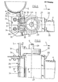
- FIGs 2, 3 and 4 show a first embodiment of the stabilization device (26) arranged according to the invention.
- the rear end of the arm (4) is provided with a casing (27) which is fixed to the arm tube (4) by means of the screws (28).
- This casing (27) is mounted on the chassis (5) of the machine so as to be able to pivot around the axis (6) which corresponds to the longitudinal axis of the drive shaft (29) of the drive housed in a manner known to those skilled in the art, in the arm (4), and which serve to rotate the disc (2) around its axis (8).
- the casing (27) is linked to the chassis (5) by means of two bearings (30) which are fixed to the chassis (5) by means of the screws (31).
- Each casing (27) has at the rear, taking into account the direction of advance (7) of the machine at work, a projection (32).
- This protuberance (32) extends between two deformable members (33, 331) which, in the example, each consist of a block of rubber or a similar material.
- These deformable members (33, 331) have a substantially rectangular section and are each held on the frame (5) by a support (34) in the form of an angle.
- the two supports (34) are arranged relative to each other so as to form substantially a lying U open towards the front. These two supports (34) are held in this relative position insofar as they are welded to two plates (35).
- This assembly of supports (34) - plates (35) is mounted on the chassis (5) using the bolts (36).
- the two deformable members (33, 331) are each bonded to its respective support (34).
- the set of deformable members (33, 331) - supports (34) - plates (35) forms a complete stabilization device (26).
- Figure 4 shows the operation of the device.
- the maximum upper position of the arm (4) has been shown. This happens when the free end of the arm (4) passes over a very large bump.
- the projection (32) of the casing (27) is shown in the maximum low position of the arm (4). This happens when the free end of the arm (4) passes through a very large hole or during transport, when the chassis (5) is far from the ground (19).
- Figure 5 shows a second embodiment of a stabilization device (261) arranged according to the invention.
- the arm (4) is provided with a casing (40) which comprises at the rear, taking into account the direction of advance (7) of the machine at work, two support legs (41).
- the casing (40) is fixed to the arm tube (4) by means of screws (28).
- the casing (40) is linked to the chassis (5) by means of two bearings (30) which allow rotation around the axis (6).
- the frame (5) is provided with a cleat (42) which extends between two plates (43) to which it is fixed by welding for example. These plates (43) are fixed to the chassis (5) by means of screws (36).
- a stopper (45) is fixed between the lower edges of the plates (43), while a stopper (46) is fixed between the upper edges of said plates (43).
- the stops (45 and 46) have the same function as the stops (38 and 39) of the example of FIGS. 2 to 4, that is to say limit the rotation of the arm (4) upwards or low. Blocking the rotation of the arm (4) upwards, respectively downward occurs when the lower support tab (41) of the housing (40) comes into contact with the stop (1 q ), respectively when the upper support tab (41) comes into contact with the stop (46).
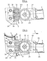
- Figure 6 shows a third embodiment of a stabilization device (262) arranged according to the invention.
- the arm (4) is provided with a casing (47) which has at its upper part, a projection (48).
- the casing (47) is fixed to the arm tube (4) by means of screws (28).
- the casing (47) is linked to the chassis (5) by means of two bearings (30) which are fixed to the chassis (5) by means of screws (31) and which allow the casing (47) to turn around the axis (6).
- the chassis (5) is also provided with a support flange (49) which is fixed there by welding for example.
- This support flange (49) has a hole (50) which is crossed by a threaded rod (51).
- a nut (52) On the end of the threaded rod (51) which passes through the support flange (49), is screwed a nut (52) which connects said threaded rod (51) to said support flange (49).
- the threaded rod (51) also passes through a hole (53) arranged in the projection (48) of the casing (47).
- a deformable member (54) which is composed of a plurality of spring washers threaded on the threaded rod (51).
- another nut (55) was screwed after having inserted a second deformable member (541) also composed of a plurality of spring washers.
- This second deformable member (541) extends between the projection (48) of the casing (47) and the nut (55).
- the position of the support element which maintains the deformable member (541), in this case the nut (55) and the threaded rod (51), is adjustable.
- this stabilization device Taking into account the construction of this stabilization device and thanks to the possible adjustment of the nut (55), it is possible to adjust the stiffness of the stabilization device. Indeed, by more or less screwing the nut (55), the deformable members (54, 541) are more or less prestressed. It is therefore possible, by this means, to adapt the stiffness of the stabilization device to the various conditions under which the mower is called to work.
- the limitation of the rotation of the arm (4) upwards or downwards is carried out by the deformable members (54, 541) themselves.
- the spring washers which make up the deformable members (54, 541) can only deform by a certain amount. When this value is reached, the deformable members become undeformable and block the rotation of the arm (4) around the axis (6).
- Figure 7 shows a fourth embodiment of a stabilization device (263) arranged according to the invention.
- the arm (4) is provided with a casing (56) which comprises at its rear part, taking into account the direction of advance (7) of the machine at work, a yoke (57).
- the casing (56) is fixed to the arm tube (4) by means of screws (28) not shown.
- the casing (56) is linked to the chassis (5) by means of two bearings (30) which have not been shown so as not to clutter the figure.
- the chassis (5) is also also provided with a yoke (58). Between the yokes (57 and 58) extends a stabilization device (263) which is fixed to it by means of pins (59, 60).
- This stabilization device (263) is a damping cylinder which comprises a rod (61) and a body (62).
- the body (62) consists of two parts, a primary part (63) and a secondary part (64).
- the primary part (63) has a hole (65) on which connects a hydraulic line which will bring the fluid from the towing vehicle for example to the device.
- the hole (65) communicates with a bore (66) produced in the primary part (63) along the longitudinal axis (67) of the device.
- This bore (66) defines the cylinder actuator of the device.
- In this bore (66) is introduced the end (68) of the rod (61).
- the seal between the bore (66) and the end (68) of the rod (61) is ensured by a seal (69).
- the rod (61) has a shoulder (70) which has a diameter larger than the diameter of the rest of the rod (61).
- This shoulder (70) extends inside a bore (71) produced in the secondary part (64) along the longitudinal axis (67) of the device.
- the free end of the rod (61) it extends outside the secondary part (64) through a bore (72) produced concentrically with the bore (71).
- the seal between the rod (61) and the bore (72) is produced using a seal (73).
- the bore (71) and the shoulder (70) define the shock cylinder and the shock piston.
- the secondary part (64) is screwed onto the primary part (63).
- the primary part (63) comprises a male thread (74) and the secondary part (64), a female thread (75).
- the seal between the two parts (63 and 64) is achieved by means of a seal (76).
- the shoulder (70) divides the damping cylinder (71) into two chambers, a primary chamber (77) and a secondary chamber (78).
- the outside diameter of the shoulder (70) is slightly smaller than the inside diameter of the damping cylinder (71). In this way, the fluid contained in the damping cylinder can be transferred from the primary chamber (77) into the secondary chamber (78) when the free end of the arm (4) rises, and vice versa from the secondary chamber (78) in the primary chamber (77) when the free end of the arm (4) descends.
- the end (68) of the rod (61) has a hole (79) whose axis coincides with the longitudinal axis (67). This hole (79) communicates with an orifice (80) drilled in the rod (61) perpendicular to the longitudinal axis (67) and opening into the damping cylinder (71).
- a sleeve (81) which has an axial orifice (82) passing right through it.
- This axial orifice (82) is blocked by a ball (83) held in place by a spring (84).
- the ball (83) is held in place by the spring (84) so that the fluid can pass from the cylinder to the damper but not from the damper to the cylinder.
- the damping cylinder (71) may be provided with a removable plug, not shown. It will be understood, when the damper is completely filled with fluid, that the fluid which arrives in the jack can no longer repel the ball (83).
- the shock absorber operates as follows. In work, that is to say when the arm (4) rests on the ground (19), the fluid contained in the jack can freely enter or leave the jack. Thus, when the free end of the arm (4) is lifted by a bump, the arm (4) rotates around the axis (6) anticlockwise, and the casing (56) pulls on the rod (61), forcing it to come out of the body (62). The fluid contained in the primary chamber (77) is then transferred to the secondary chamber (78) through the constriction formed between the damping cylinder (71) and the shoulder (70). Given the small dimension of this constriction, the transfer of the fluid is braked. This braking almost immediately stops the rise of the arm (4) as soon as the arm (4) reaches the top of the bump.
- the weight of the arm (4) rotates it around the axis (6) clockwise, and the housing (56) then pushes on the rod (61) forcing it to re-enter the body (62 ).
- the arm (4) thus returns to its position in contact with the ground (19).
- the work of the shock absorber is similar when the arm (4) passes over a hole. In this case, it is the descent of the arm (4) which is braked by the throttle braking the transfer of the fluid from the chamber (78) into the chamber (77).
- the stabilization device and in particular the point of the arm (4) which acts on the device during the pivoting of the arm (4) are located in the front vicinity (FIG. 6) or at the rear ( Figures 1, 2, 3, 4, 5 and 7) of the axis (6).
- the stabilization device arranged according to the invention is therefore relatively far from the area of the cutting heads (1), so that the risks of catching cut forage are relatively low, even non-existent.
- the stabilization devices (26, 261, 262, 263) described in the examples are relatively compact, which can also be an additional factor in reducing the risks of catching cut forage.
- the embodiments described are not limiting. It is thus for example possible to combine different solutions together. Indeed, by way of non-unique example, the stabilization device (26) of Figure 2 could for example be replaced by the stabilization device (262) of Figure 6 placed substantially vertically.
Landscapes
- Life Sciences & Earth Sciences (AREA)
- Environmental Sciences (AREA)
- Harvester Elements (AREA)
Abstract
Selon l'invention, le point du bras (4) qui agit sur le dispositif de stabilisation (26) pendant le pivotement du bras (4), est situé dans le voisinage de l'axe (6) de pivotement du bras (4), ou derrière cet axe (6). L'invention concerne également un vérin amortisseur utilisé comme dispositif de stabilisation (26), ainsi que le dispositif de stabilisation (26). La présente invention trouve son application dans le domaine du machinisme agricole.According to the invention, the point of the arm (4) which acts on the stabilization device (26) during the pivoting of the arm (4), is located in the vicinity of the axis (6) of pivoting of the arm (4) , or behind this axis (6). The invention also relates to a damping cylinder used as a stabilization device (26), as well as the stabilization device (26). The present invention finds its application in the field of agricultural machinery.
Description
La présente invention concerne une faucheuse munie d'au moins une tête de coupe s'étendant à l'extrémité libre d'un bras qui est monté à son autre extrémité sur le châssis de la machine de manière à pouvoir pivoter à l'encontre d'un dispositif de stabilisation autour d'un axe dirigé transversalement par rapport à la direction d'avancement de la machine pendant le travail.The present invention relates to a mower provided with at least one cutting head extending at the free end of an arm which is mounted at its other end on the chassis of the machine so as to be able to pivot against the 'A stabilization device around an axis directed transversely to the direction of advance of the machine during work.
On connaît une telle faucheuse dont le dispositif de stabilisation est constitué par un amortisseur télescopique. Le point d'ancrage de cet amortisseur télescopique sur le bras est sensiblement situé à mi-distance entre l'axe de rotation de la ou des têtes de coupe et l'axe dirigé transversalement par rapport à la direction d'avancement de la machine pendant le travail autour duquel peut pivoter le bras. A partir de ce point d'ancrage, l'amortisseur télescopique s'étend vers l'arrière et vers le haut.Such a mower is known, the stabilization device of which consists of a telescopic damper. The anchor point of this telescopic shock absorber on the arm is substantially located midway between the axis of rotation of the cutting head (s) and the axis directed transversely to the direction of advance of the machine during the work around which the arm can pivot. From this anchor point, the telescopic shock absorber extends backwards and upwards.
Cet agencement présente des inconvénients. En effet, compte tenu de la position de cet amortisseur télescopique, et notamment de son point d'ancrage sur le bras, il arrive en pratique assez fréquemment que du fourrage coupé par la ou les têtes de coupe reste accroché audit amortisseur télescopique. Ces accrochages de fourrage sont gênants car ils peuvent provoquer des bourrages.This arrangement has drawbacks. In fact, taking into account the position of this telescopic damper, and in particular its anchoring point on the arm, it happens quite frequently in practice that fodder cut by the cutting head or heads remains attached to said telescopic damper. These catchings of fodder are troublesome because they can cause jams.
Par ailleurs, lorsque la faucheuse est équipée d'un moyen de transport du fourrage coupé tel qu'un tambour muni de saillies et tournant autour d'un axe dirigé transversalement par rapport à la direction d'avancement de la machine pendant le travail, il peut être avantageux, pour augmenter l'efficacité du moyen de transport, de disposer également des saillies dans le plan vertical contenant un bras. Or avec l'agencement de l'amortisseur télescopique tel qu'il est réalisé sur la faucheuse connue, il est impossible d'agencer de telles saillies.Furthermore, when the mower is equipped with a means of transporting cut forage such as a drum provided with projections and rotating about an axis directed transversely to the direction of advance of the machine during work, it may be advantageous, to increase the efficiency of the means of transport, also to have projections in the vertical plane containing an arm. However, with the arrangement of the telescopic damper as it is produced on the known mower, it is impossible to arrange such projections.
La présente invention a pour but de remédier à ces inconvénients.The object of the present invention is to remedy these disadvantages.
Pour ce faire, la faucheuse selon l'invention est caractérisée par le fait que le point du bras qui agit sur le dispositif de stabilisation pendant le pivotement du bras, est situé dans le voisinage de l'axe de pivotement du bras ou derrière cet axe.To do this, the mower according to the invention is characterized in that the point of the arm which acts on the stabilization device during the pivoting of the arm, is located in the vicinity of the pivot axis of the arm or behind this axis .
Avec cette caractéristique, le dispositif de stabilisation et notamment le point du bras qui agit sur le dispositif de stabilisation pendant le pivotement du bras, sont relativement éloignés de la ou des têtes de coupe, de sorte que les risques d'accrochage de fourrage coupé sont nettement diminués, voire supprimés.With this characteristic, the stabilization device and in particular the point of the arm which acts on the stabilization device during the pivoting of the arm, are relatively distant from the cutting head or heads, so that the risks of catching cut forage are markedly reduced or even eliminated.
Ces risques d'accrochage sont notamment sensiblement supprimés lorsque le dispositif de stabilisation est situé en tout ou en partie derrière l'axe de pivotement du bras.These risks of snagging are notably substantially eliminated when the stabilization device is located in whole or in part behind the pivot axis of the arm.
Ces risques d'accrochage sont également diminués, voire supprimés lorsque l'encombrement du dispositif de stabilisation qui comporte d'une manière connue en soi au moins un organe déformable, est petit.These risks of catching are also reduced, or even eliminated when the size of the stabilization device which comprises in a manner known per se at least one deformable member, is small.
De ce fait, il suffit par exemple que seul le pivotement du bras vers le haut se fasse à l'encontre d'un dispositif de stabilisation. En effet, un rôle important du dispositif de stabilisation est de maintenir le mieux possible la position de la tête de coupe par rapport à la surface du sol pour obtenir une bonne qualité de coupe. Ceci veut dire qu'on empêche la tête de coupe de sautiller continuellement avec une amplitude plus ou moins grande, lorsqu'elle passe sur les nombreuses bosses que présente le terrain sur lequel opère la faucheuse. Cependant, lorsque la tête de coupe passe dans un trou, elle peut prendre d'elle-même, du fait de son poids, la position la plus proche de la surface du sol.Therefore, it suffices for example that only the pivoting of the arm upwards takes place against a stabilization device. In fact, an important role of the stabilization device is to maintain as best as possible the position of the cutting head relative to the surface of the ground in order to obtain good cutting quality. This means that the cutting head is prevented from continuously hopping with a greater or lesser amplitude when it passes over the numerous bumps in the terrain on which the mower operates. However, when the cutting head passes through a hole, it can take on its own, due to its weight, the position closest to the ground surface.
Néanmoins, pour éviter des contraintes trop importantes sur le bras au sortir d'un trou dans lequel était descendue la tête de coupe, il est avantageux de freiner également la descente de la tête de coupe, c'est-à-dire le pivotement du bras vers le bas.However, to avoid excessive stress on the arm at the end of a hole in which the cutting head had been lowered, it is advantageous to also slow down the lowering of the cutting head, that is to say the pivoting of the arms down.
A cet effet, dans une réalisation selon l'invention, le dispositif de stabilisation comporte deux organes déformables qui agissent entre le bras et le châssis de la machine. Avantageusement, il est possible que, soit le bras, soit le châssis de la machine comporte une excroissance qui s'étend entre les deux organes déformables. Ces organes déformables peuvent par ailleurs s'étendre entre deux éléments support solidaires soit du châssis de la machine, soit du bras.To this end, in an embodiment according to the invention, the stabilization device comprises two deformable members which act between the arm and the chassis of the machine. Advantageously, it is possible that either the arm or the chassis of the machine has a projection which extends between the two deformable members. These deformable members can also extend between two support elements integral either with the chassis of the machine or with the arm.
Avantageusement également l'un au moins des éléments support solidaires soit du châssis, soit du bras peut être réglable.Advantageously also at least one of the support elements integral either with the chassis or with the arm can be adjustable.
Ce réglage de l'un au moins desdits éléments support peut par exemple dans l'invention servir à précontraindre les organes déformables. Cette précontrainte des organes déformables permet par exemple d'adapter le dispositif de stabilisation aux différentes conditions dans lesquelles est amenée à travailler la faucheuse.This adjustment of at least one of said support elements can for example in the invention be used to prestress the deformable members. This prestressing of the deformable members makes it possible for example to adapt the stabilization device to the different conditions under which the mower is required to work.
Un tel élément support réglable peut dans l'invention être constitué par un boulon ou tout moyen similaire.Such an adjustable support element can in the invention consist of a bolt or any similar means.
Dans l'invention, les organes déformables peuvent être constitués par des blocs en caoutchouc ou en une matière similaire.In the invention, the deformable members can be constituted by blocks of rubber or a similar material.
Ils peuvent aussi être constitués par des ressorts, et avantageusement par un empilage de rondelles-ressort.They can also be constituted by springs, and advantageously by a stack of spring washers.
Suivant une autre caractéristique de l'invention, le dispositif de stabilisation est un amortisseur hydraulique. Avantageusement cet amortisseur hydraulique peut en plus être un vérin hydraulique.According to another characteristic of the invention, the stabilization device is a hydraulic shock absorber. Advantageously, this hydraulic damper can also be a hydraulic cylinder.
Il est ainsi possible en sus d'augmenter la garde au sol de la machine pendant le transport en faisant pivoter vers le haut les bras avec leur tête de coupe parallèlement à l'éloignement du châssis de la machine du sol. Il est à noter que dans la faucheuse de l'art antérieur, il existe des petits vérins pour faire pivoter les bras et leur tête de coupe vers le haut. Le vérin amortisseur de l'invention se distingue de cet art antérieur par le fait que le vérin et le dispositif de stabilisation sont réalisés en un seul sous-ensemble. Ceci permet de diminuer substantiellement l'encombrement. En sus, le prix de revient peut être abaissé.It is thus possible in addition to increasing the ground clearance of the machine during transport by rotating the arms upwards with their cutting head parallel to the distance of the chassis of the machine from the ground. It should be noted that in the prior art mower, there are small jacks for pivoting the arms and their cutting head upwards. The shock absorber of the invention differs from this art prior by the fact that the cylinder and the stabilization device are made in a single sub-assembly. This makes it possible to substantially reduce the size. In addition, the cost price can be lowered.
Suivant une réalisation de l'invention, le vérin amortisseur comporte deux mécanismes piston-cylindre. Ces deux mécanismes piston-cylindre peuvent communiquer entre eux au moyen d'une ouverture bouchée par un organe qui empêche la sortie du fluide du piston-cylindre amortisseur vers le piston-cylindre vérin. Cet agencement permet de faire aisément la purge du piston-cylindre amortisseur.According to one embodiment of the invention, the damping cylinder comprises two piston-cylinder mechanisms. These two piston-cylinder mechanisms can communicate with each other by means of an opening blocked by a member which prevents the exit of the fluid from the damping piston-cylinder towards the jack piston-cylinder. This arrangement makes it possible to easily purge the damping piston-cylinder.
Le vérin amortisseur de l'invention est relativement ccmpact et facilement réalisable lorsque les deux pistons forment une seule pièce, et que les cylindres sont réalisés dans deux parties différentes qui sont liées l'une à l'autre. Cette liaison est avantageusement réalisée par vissage.The damping cylinder of the invention is relatively ccmpact and easily achievable when the two pistons form a single piece, and the cylinders are produced in two different parts which are linked to each other. This connection is advantageously carried out by screwing.
Suivant une caractéristique supplémentaire de l'invention, le pivotement du bras vers le haut et/ou vers le bas est d'une manière connue en soi, limité par une butée.According to an additional characteristic of the invention, the pivoting of the arm upwards and / or downwards is in a manner known per se, limited by a stop.
Ces butées peuvent dans l'invention, être constituées par les organes déformables eux-mêmes.These stops can in the invention be constituted by the deformable members themselves.
Selon une autre réalisation, le bras ou le châssis de la machine peuvent comporter au moins un index qui collabore avec des butées solidaires du châssis de la machine, respectivement du bras. Avantageusement, ce ou ces index peuvent être constitués par l'excroissance du bras ou du châssis de la machine qui s'étend entre les deux organes déformables.According to another embodiment, the arm or the chassis of the machine can comprise at least one index which collaborates with stops integral with the chassis of the machine, respectively of the arm. Advantageously, this or these indexes can be formed by the projection of the arm or of the chassis of the machine which extends between the two deformable members.
Dans le cas du vérin amortisseur de l'invention, le pivotement du bras vers le haut et/ou vers le bas peut être limité par la course possible du piston amortisseur dans le cylindre amortisseur.In the case of the shock absorber cylinder of the invention, the pivoting of the arm upwards and / or downwards can be limited by the possible stroke of the shock absorber piston in the shock absorber cylinder.
L'invention concerne également un vérin amortisseur tel que décrit ci-dessus.The invention also relates to a damping cylinder as described above.
D'autres caractéristiques et avantages de l'invention apparaitront dans la description suivante de quelques exemples de réalisation non limitatifs, faite à l'aide du dessin annexé sur lequel :
- - La figure 1 représente une vue latérale partiellement en coupe d'une faucheuse selon l'invention,
- - La figure 2 représente une vue latérale partiellement en coupe d'un premier exemple de réalisation d'un dispositif de stabilisation agencé selon l'invention,
- - La figure 3 représente une demi-vue de dessus partiellement en coupe de l'exemple de réalisation de la figure 2,
- - La figure 4 représente une vue latérale partiellement en coupe de l'exemple de réalisation des figures 2 et 3, montrant le mode de fonctionnement du dispositif de stabilisation,
- - La figure 5 représente une vue latérale partiellement en coupe d'un deuxième exemple de réalisation d'un dispcsitif de stabilisation agencé selon l'invention,
- - La figure 6 représente une vue latérale partiellement en coupe d'un troisième exemple de réalisation d'un dispositif de stabilisation agencé selon l'invention,
- - La figure 7 représente une vue latérale partiellement en coupe d'un quatrième exemple de réalisation d'un dispositif de stabilisation agencé selon l'invention.
- FIG. 1 represents a side view partially in section of a mower according to the invention,
- FIG. 2 represents a side view partially in section of a first embodiment of a stabilization device arranged according to the invention,
- FIG. 3 represents a half-view from above partially in section of the embodiment of FIG. 2,
- FIG. 4 represents a partially sectioned side view of the embodiment of FIGS. 2 and 3, showing the operating mode of the stabilization device,
- FIG. 5 represents a side view partially in section of a second embodiment of a stabilization device arranged according to the invention,
- FIG. 6 represents a side view partially in section of a third embodiment of a stabilization device arranged according to the invention,
- - Figure 7 shows a side view partially in section of a fourth embodiment of a stabilization device arranged according to the invention.
La figure 1 montre une faucheuse munie de têtes de coupe (1). Ces têtes de coupe (1) se composent d'un disque rotatif (2) muni d'outils de coupe (3). Le disque (2) est fixé à l'extrémité libre d'un bras (4) de sorte que ladite extrémité du bras (4) se trouve sous le disque (2). Le bras (4) est lié au châssis (5) de la machine de manière à pouvoir pivoter autour de l'axe (6). Cet axe (6) est dirigé transversalement par rapport à la direction d'avancement de la machine pendant le travail définie par la flèche (7). La rotation du disque (2) autour de l'axe (8) est produite par des moyens d'entraînement qui sont à la portée de l'homme de l'art.Figure 1 shows a mower with cutting heads (1). These cutting heads (1) consist of a rotating disc (2) provided with cutting tools (3). The disc (2) is fixed to the free end of an arm (4) so that said end of the arm (4) is located under the disc (2). The arm (4) is linked to the chassis (5) of the machine so that it can pivot around the axis (6). This axis (6) is directed transversely to the direction of advance of the machine during work defined by the arrow (7). The rotation of the disc (2) about the axis (8) is produced by drive means which are within the reach of those skilled in the art.
Au-dessus des bras (4) s'étend un tambour de transport (9) du fourrage coupé par les têtes de coupe (1), dont l'axe de rotation (10) est dirigé transversalement à la direction (7). Le tambour de transport (9) est muni de saillies (11, 12). Ce tambour de transport (9) est entraîné en rotation autour de l'axe (10) dans le sens indiqué par la flèche (13) par des moyens d'entraînement qui sont à la portée de l'homme de l'art. Les saillies (11) s'étendent entre deux bras (4) voisins et leur longueur est telle que leur extrémité libre (14) s'étend, pendant la rotation du tambour (9), jusque dans l'espace situé entre les bras (4). Les saillies (12) quant à elles s'étendent dans les plans verticaux qui contiennent les bras (4), et leur longueur est telle que leur extrémité libre (15) ne touche pas la face supérieure (16) des bras (4) lorsque ceux-ci se trouvent dans leur position haute maximale.Above the arms (4) extends a drum of transport (9) of the cut cut by the cutting heads (1), whose axis of rotation (10) is directed transverse to the direction (7). The transport drum (9) is provided with projections (11, 12). This transport drum (9) is rotated about the axis (10) in the direction indicated by the arrow (13) by drive means which are within the reach of ordinary skill in the art. The projections (11) extend between two neighboring arms (4) and their length is such that their free end (14) extends, during the rotation of the drum (9), into the space between the arms ( 4). The projections (12) meanwhile extend in the vertical planes which contain the arms (4), and their length is such that their free end (15) does not touch the upper face (16) of the arms (4) when these are in their maximum high position.
Au-dessus du tambour de transport (9) est agencé un capot (17) qui forme avec le tambour de transport (9) un canal de transport (18).Above the transport drum (9) is arranged a cover (17) which forms with the transport drum (9) a transport channel (18).
A l'arrière, le châssis (5) de la machine s'appuie sur le sol (19) à l'aide de roues (20). Les roues (20) sont liées au châssis (5) par l'intermédiaire d'un balancier (21) qui est articulé à l'une de ses extrémités sur le moyeu (22) de la roue (20), et à son autre extrémité, sur un pivot (23) agencé à la partie inférieure du châssis (5). Entre la partie haute du châssis (5) et le balancier (21) est mcnté un vérin (24) qui permet d'éloigner le châssis (5) du sol (19) pour le transport.At the rear, the chassis (5) of the machine rests on the ground (19) using wheels (20). The wheels (20) are linked to the chassis (5) by means of a balance (21) which is articulated at one of its ends on the hub (22) of the wheel (20), and at its other end, on a pivot (23) arranged at the lower part of the chassis (5). Between the upper part of the chassis (5) and the balance (21) is mounted a jack (24) which allows the chassis (5) to be moved away from the ground (19) for transport.
A l'avant du châssis (5) et dans sa partie supérieure est amarré de manière connue de l'homme de l'art, un timon (25) qui sert à relier la machine à un véhicule tracteur non représenté. Les moyens d'entraînement des disques (2) et du tambour de transport (9) sont par exemple entraînés par un arbre de transmission non représenté qui transmet le mouvement depuis la prise de force du véhicule tracteur jusqu'auxdits moyens d'entraînement.At the front of the chassis (5) and in its upper part is moored in a manner known to those skilled in the art, a drawbar (25) which serves to connect the machine to a tractor vehicle not shown. The drive means of the discs (2) and the transport drum (9) are for example driven by a not shown transmission shaft which transmits the movement from the PTO of the towing vehicle to said drive means.
Près de l'extrémité du bras (4) où le bras (4) est articulé sur le châssis (5), est agencé un dispositif de stabilisation (26) qui sera décrit ci-après plus en détail.Near the end of the arm (4) where the arm (4) is articulated on the frame (5), is arranged a stabilization device (26) which will be described below in more detail.
Les figures 2, 3 et 4 montrent un premier exemple de réalisation du dispositif de stabilisation (26) agencé selon l'invention. L'extrémité arrière du bras (4) est munie d'un carter (27) qui est fixé sur le tube du bras (4) au moyen des vis (28). Ce carter (27) est monté sur le châssis (5) de la machine de manière à pouvoir pivoter autour de l'axe (6) qui correspond à l'axe longitudinal de l'arbre d'entraînement (29) des moyens d'entraînement logés d'une manière connue de l'homme de l'art, dans le bras (4), et qui servent à faire tourner le disque (2) autour de son axe (8). Pour ce faire, le carter (27) est lié au châssis (5) au moyen de deux paliers (30) qui sont fixés sur le châssis (5) au moyen des vis (31).Figures 2, 3 and 4 show a first embodiment of the stabilization device (26) arranged according to the invention. The rear end of the arm (4) is provided with a casing (27) which is fixed to the arm tube (4) by means of the screws (28). This casing (27) is mounted on the chassis (5) of the machine so as to be able to pivot around the axis (6) which corresponds to the longitudinal axis of the drive shaft (29) of the drive housed in a manner known to those skilled in the art, in the arm (4), and which serve to rotate the disc (2) around its axis (8). To do this, the casing (27) is linked to the chassis (5) by means of two bearings (30) which are fixed to the chassis (5) by means of the screws (31).
Chaque carter (27) comporte à l'arrière, compte tenu du sens d'avancement (7) de la machine au travail, une excroissance (32). Cette excroissance (32) s'étend entre deux organes déformables (33, 331) qui, dans l'exemple, sont chacun constitués par un bloc en caoutchouc ou en une matière similaire. Ces organes déformables (33, 331) ont une section sensiblement rectangulaire et sont chacun maintenus sur le châssis (5) par un support (34) en forme de cornière. Les deux supports (34) sont disposés l'un par rapport à l'autre de sorte à former sensiblement un U couché ouvert vers l'avant. Ces deux supports (34) sont maintenus dans cette position relative dans la mesure où ils sont soudés sur deux plaques (35). Cet ensemble supports (34) - plaques (35) est monté sur le châssis (5) à l'aide des boulons (36). Il est possible, dans le cadre de l'invention, que les deux organes déformables (33, 331) soient chacun collés sur son support (34) respectif. De cette sorte, l'ensemble organes déformables (33, 331) - supports (34) - plaques (35) forme un dispositif de stabilisation (26) complet.Each casing (27) has at the rear, taking into account the direction of advance (7) of the machine at work, a projection (32). This protuberance (32) extends between two deformable members (33, 331) which, in the example, each consist of a block of rubber or a similar material. These deformable members (33, 331) have a substantially rectangular section and are each held on the frame (5) by a support (34) in the form of an angle. The two supports (34) are arranged relative to each other so as to form substantially a lying U open towards the front. These two supports (34) are held in this relative position insofar as they are welded to two plates (35). This assembly of supports (34) - plates (35) is mounted on the chassis (5) using the bolts (36). It is possible, in the context of the invention, that the two deformable members (33, 331) are each bonded to its respective support (34). In this way, the set of deformable members (33, 331) - supports (34) - plates (35) forms a complete stabilization device (26).
Comme visible sur les figures 2 et 4, il existe un certain espace (37) entre les deux supports (34) dans lequel s'étend l'extrémité libre de l'excroissance (32) du carter (27). Les deux supports (34) constituent ainsi également des butées (38, 39) qui limitent la rotation de l'excroissance (32) donc du bras (4) autour de l'axe (6) vers le haut et vers le bas. Cette disposition permet ainsi d'une part d'éviter une interférence entre le bras (4) et le tambour de transport (9), et d'autre part de maintenir le bras (4) dans une certaine position par rapport au sol (19) lorsque le châssis (5) est en position haute de transport.As shown in Figures 2 and 4, there is a certain space (37) between the two supports (34) in which extends the free end of the projection (32) of the casing (27). The two supports (34) thus also constitute stops (38, 39) which limit the rotation of the projection (32) and therefore of the arm (4) around the axis (6) upwards and downwards. This arrangement thus makes it possible on the one hand to avoid interference between the arm (4) and the transport drum (9), and on the other hand to maintain the arm (4) in a certain position relative to the ground (19 ) when the chassis (5) is in the high transport position.
La figure 4 visualise le fonctionnement du dispositif. En traits pleins, on a représenté la position haute maximale du bras (4). Ceci arrive quand l'extrémité libre du bras (4) passe sur une très grande bosse. En traits mixtes, on a représenté l'excroissance (32) du carter (27) dans la position basse maximale du bras (4). Ceci arrive quand l'extrémité libre du bras (4) passe dans un très grand trou ou au transport, lorsque le châssis (5) est éloigné du sol (19).Figure 4 shows the operation of the device. In solid lines, the maximum upper position of the arm (4) has been shown. This happens when the free end of the arm (4) passes over a very large bump. In phantom, the projection (32) of the casing (27) is shown in the maximum low position of the arm (4). This happens when the free end of the arm (4) passes through a very large hole or during transport, when the chassis (5) is far from the ground (19).
Lorsque l'extrémité libre du bras (4) passe sur une bosse, le bras (4) tourne autour de l'axe (6). L'excroissance (32) du carter (27) qui tourne avec le bras (4), écrase alors l'organe déformable (33) inférieur. Cet écrasement de l'organe déformable (33) freine la rotation du bras (4). Ainsi, lorsque l'extrémité libre du bras (4) atteint le sommet de la bosse, la rotation s'arrête presque aussitôt, et l'organe déformable (33) force le bras (4) à revenir rapidement en contact avec la surface du sol (19), ce qui garantit une bonne qualité de coupe. Lorsque la dimension de la bosse est très importante, le bras (4) peut pivoter autour de l'axe (6) jusqu'à ce que l'excroissance (32) arrive en contact avec la butée (38). Le pivotement du bras (4) est alors bloqué. Ceci évite, comme dit plus haut, une interférence du bras (4) avec le tambour de transport (9).When the free end of the arm (4) passes over a bump, the arm (4) rotates around the axis (6). The protuberance (32) of the casing (27) which rotates with the arm (4), then crushes the lower deformable member (33). This crushing of the deformable member (33) brakes the rotation of the arm (4). Thus, when the free end of the arm (4) reaches the top of the hump, the rotation stops almost immediately, and the deformable member (33) forces the arm (4) to quickly come back into contact with the surface of the ground (19), which guarantees a good quality of cut. When the dimension of the bump is very large, the arm (4) can pivot around the axis (6) until the projection (32) comes into contact with the stop (38). The pivoting of the arm (4) is then blocked. This avoids, as said above, interference of the arm (4) with the transport drum (9).
Lorsque l'extrémité libre du bras (4) rencontre un trou, le poids du bras (4) fait descendre ladite extrémité libre dans le trou. Pour ne pas provoquer des contraintes trop importantes dans le bras (4) ou dans le disque (2) au sortir du trou lorsque celui-ci est relativement profond, la rotation du bras (4) vers le bas autour de l'axe (6) est freinée par l'organe déformable (331) supérieur qui est écrasé par l'excroissance (32). De cette sorte, l'extrémité libre du bras (4) peut passer au-dessus d'un trou sans que ladite extrémité n'ait eu le temps de descendre jusqu'au fond de celui-ci. La rotation du bras (4) vers le bas est limitée par la butée (39) pour les raisons dites plus haut.When the free end of the arm (4) meets a hole, the weight of the arm (4) lowers said free end into the hole. In order not to cause excessive stresses in the arm (4) or in the disc (2) at the end of the hole when the latter is relatively deep, the rotation of the arm (4) down around the axis (6 ) is braked by the upper deformable member (331) which is crushed by the projection (32). In this way, the free end of the arm (4) can pass over a hole without the said end having had time to descend to the bottom thereof. The rotation of the arm (4) downwards is limited by the stop (39) for the reasons stated above.
La figure 5 montre un deuxième exemple de réalisation d'un dispositif de stabilisation (261) agencé selon l'invention. Dans cet exemple, le bras (4) est muni d'un carter (40) qui comporte à l'arrière, compte tenu du sens d'avancement (7) de la machine au travail, deux pattes support (41). Tout comme dans l'exemple précédent, le carter (40) est fixé sur le tube du bras (4) au moyen de vis (28). De même, le carter (40) est lié au châssis (5) au moyen de deux paliers (30) qui autorisentsa rotation autour de l'axe (6).Figure 5 shows a second embodiment of a stabilization device (261) arranged according to the invention. In this example, the arm (4) is provided with a casing (40) which comprises at the rear, taking into account the direction of advance (7) of the machine at work, two support legs (41). As in the previous example, the casing (40) is fixed to the arm tube (4) by means of screws (28). Similarly, the casing (40) is linked to the chassis (5) by means of two bearings (30) which allow rotation around the axis (6).
Le châssis (5) est muni d'un taquet (42) qui s'étend entre deux plaques (43) auxquelles il est fixé par soudure par exemple. Ces plaques (43) sont fixées sur le châssis (5) au moyen de vis (36).The frame (5) is provided with a cleat (42) which extends between two plates (43) to which it is fixed by welding for example. These plates (43) are fixed to the chassis (5) by means of screws (36).
Entre le taquet (42) du châssis (5) et les pattes support (41) du carter (40) s'étendent deux organes déformables (44, 441) similaires aux organes déformables (33, 331) des figures 2 à 4.Between the cleat (42) of the chassis (5) and the support lugs (41) of the casing (40) extend two deformable members (44, 441) similar to the deformable members (33, 331) of FIGS. 2 to 4.
Entre les bords inférieurs des plaques (43) est fixée une butée (45), alors qu'entre les bords supérieurs desdites plaques (43) est fixée une butée (46). Les butées (45 et 46) ont la même fonction que les butées (38 et 39) de l'exemple des figures 2 à 4, c'est-à-dire limiter la rotation du bras (4) vers le haut ou vers le bas. Le blocage de la rotation du bras (4) vers le haut, respectivement vers le bas se réalise lorsque la patte support (41) inférieure du carter (40) arrive en contact avec la butée (1q), respectivement lorsque la patte support (41) supérieure arrive en contact avec la butée (46).A stopper (45) is fixed between the lower edges of the plates (43), while a stopper (46) is fixed between the upper edges of said plates (43). The stops (45 and 46) have the same function as the stops (38 and 39) of the example of FIGS. 2 to 4, that is to say limit the rotation of the arm (4) upwards or low. Blocking the rotation of the arm (4) upwards, respectively downward occurs when the lower support tab (41) of the housing (40) comes into contact with the stop (1 q ), respectively when the upper support tab (41) comes into contact with the stop (46).
La figure 6 montre un troisième exemple de réalisation d'un dispositif de stabilisation (262) agencé selon l'invention. Dans cet exemple, le bras (4) est muni d'un carter (47) qui comporte à sa partie supérieure, une excroissance (48).Figure 6 shows a third embodiment of a stabilization device (262) arranged according to the invention. In this example, the arm (4) is provided with a casing (47) which has at its upper part, a projection (48).
Tout comme dans les exemples précédents, le carter (47) est fixé sur le tube du bras (4) au moyen de vis (28). De même, le carter (47) est lié au châssis (5) au moyen de deux paliers (30) qui sont fixés sur le châssis (5) à l'aide de vis (31) et qui permettent au carter (47) de tourner autour de l'axe (6).As in the previous examples, the casing (47) is fixed to the arm tube (4) by means of screws (28). Likewise, the casing (47) is linked to the chassis (5) by means of two bearings (30) which are fixed to the chassis (5) by means of screws (31) and which allow the casing (47) to turn around the axis (6).
Le châssis (5) est par ailleurs muni d'une bride support (49) qui y est fixée par soudure par exemple. Cette bride support (49) possède un trou (50) qui est traversé par une tige filetée (51). Sur l'extrémité de la tige filetée (51) qui traverse la bride support (49), est vissé un écrou (52) qui lie ladite tige filetée (51) à ladite bride support (49).The chassis (5) is also provided with a support flange (49) which is fixed there by welding for example. This support flange (49) has a hole (50) which is crossed by a threaded rod (51). On the end of the threaded rod (51) which passes through the support flange (49), is screwed a nut (52) which connects said threaded rod (51) to said support flange (49).
La tige filetée (51) traverse par ailleurs un trou (53) aménagé dans l'excroissance (48) du carter (47).The threaded rod (51) also passes through a hole (53) arranged in the projection (48) of the casing (47).
Entre la bride support (49) et l'excroissance (48) s'étend un organe déformable (54) qui est composé par une pluralité de rondelles-ressort enfilées sur la tige filetée (51). Sur l'autre extrémité de la tige filetée (51), on a vissé un autre écrou (55) après avoir enfilé un deuxième organe déformable (541) également composé d'une pluralité de rondelles-ressort. Ce deuxième organe déformable (541) s'étend entre l'excroissance (48) du carter (47) et l'écrou (55).Between the support flange (49) and the projection (48) extends a deformable member (54) which is composed of a plurality of spring washers threaded on the threaded rod (51). On the other end of the threaded rod (51), another nut (55) was screwed after having inserted a second deformable member (541) also composed of a plurality of spring washers. This second deformable member (541) extends between the projection (48) of the casing (47) and the nut (55).
On notera que dans cet exemple, la position de l'élément support qui maintient l'organe déformable (541), en l'occurrence l'écrou (55) et la tige filetée (51), est réglable.It will be noted that in this example, the position of the support element which maintains the deformable member (541), in this case the nut (55) and the threaded rod (51), is adjustable.
Compte tenu de la ccnstruction de ce dispositif de stabilisation et grâce au réglage possible de l'écrou (55), il est possible de régler la raideur du dispositif de stabilisation. En effet, en vissant plus ou moins l'écrou (55), on précontraint plus ou moins les organes déformables (54, 541). Il est donc possible, grâce à ce moyen, d'adapter la raideur du dispositif de stabilisation aux conditions diverses dans lesquelles est appelée à travailler la faucheuse.Taking into account the construction of this stabilization device and thanks to the possible adjustment of the nut (55), it is possible to adjust the stiffness of the stabilization device. Indeed, by more or less screwing the nut (55), the deformable members (54, 541) are more or less prestressed. It is therefore possible, by this means, to adapt the stiffness of the stabilization device to the various conditions under which the mower is called to work.
On notera aussi que dans cet exemple, la limitation de la rotation du bras (4) vers le haut ou vers le bas est réalisée par les organes déformables (54, 541) eux-mêmes. En effet, les rondelles-ressort qui composent les organes déformables (54, 541) ne peuvent se déformer que d'une certaine valeur. Lorsque cette valeur est atteinte, les organes déformables deviennent indéformables et bloquent la rotation du bras (4) autour de l'axe (6).It will also be noted that in this example, the limitation of the rotation of the arm (4) upwards or downwards is carried out by the deformable members (54, 541) themselves. In fact, the spring washers which make up the deformable members (54, 541) can only deform by a certain amount. When this value is reached, the deformable members become undeformable and block the rotation of the arm (4) around the axis (6).
La figure 7 montre un quatrième exemple de réalisation d'un dispositif de stabilisation (263) agencé selon l'invention. Dans cet exemple, le bras (4) est muni d'un carter (56) qui comporte à sa partie arrière, compte tenu du sens d'avancement (7) de la machine au travail, une chape (57).Figure 7 shows a fourth embodiment of a stabilization device (263) arranged according to the invention. In this example, the arm (4) is provided with a casing (56) which comprises at its rear part, taking into account the direction of advance (7) of the machine at work, a yoke (57).
Tout comme dans les exemples précédents, le carter (56) est fixé sur le tube du bras (4) au moyen de vis (28) non représentées. De même, le carter (56) est lié au châssis (5) au moyen de deux paliers (30) qui n'ont pas été représentés pour ne pas encombrer la figure.As in the previous examples, the casing (56) is fixed to the arm tube (4) by means of screws (28) not shown. Likewise, the casing (56) is linked to the chassis (5) by means of two bearings (30) which have not been shown so as not to clutter the figure.
Le châssis (5) est par ailleurs également muni d'une chape (58). Entre les chapes (57 et 58) s'étend un dispositif de stabilisation (263) qui y est fixé au moyen d'axes (59, 60). Ce dispositif de stabilisation (263) est un vérin amortisseur qui comporte une tige (61) et un corps (62). Le corps (62) se compose de deux parties, une partie primaire (63) et une partie secondaire (64). La partie primaire (63) comporte un trou (65) sur lequel on branche une conduite hydraulique qui amènera le fluide depuis le véhicule tracteur par exemple jusqu'au dispositif. Le trou (65) communique avec un alésage (66) réalisé dans la partie primaire (63) suivant l'axe longitudinal (67) du dispositif. Cet alésage (66) définit le cylindre vérin du dispositif. Dans cet alésage (66) est introduite l'extrémité (68) de la tige (61). L'étanchéité entre l'alésage (66) et l'extrémité (68) de la tige (61) est assurée par un joint (69). Cette extrémité (68) de la tige (61) définit le piston vérin.The chassis (5) is also also provided with a yoke (58). Between the yokes (57 and 58) extends a stabilization device (263) which is fixed to it by means of pins (59, 60). This stabilization device (263) is a damping cylinder which comprises a rod (61) and a body (62). The body (62) consists of two parts, a primary part (63) and a secondary part (64). The primary part (63) has a hole (65) on which connects a hydraulic line which will bring the fluid from the towing vehicle for example to the device. The hole (65) communicates with a bore (66) produced in the primary part (63) along the longitudinal axis (67) of the device. This bore (66) defines the cylinder actuator of the device. In this bore (66) is introduced the end (68) of the rod (61). The seal between the bore (66) and the end (68) of the rod (61) is ensured by a seal (69). This end (68) of the rod (61) defines the cylinder piston.
Au dehors de la partie primaire (63), la tige (61) comporte un épaulement (70) qui a un diamètre plus grand que le diamètre du reste de la tige (61). Cet épaulement (70) s'étend à l'intérieur d'un alésage (71) réalisé dans la partie secondaire (64) suivant l'axe longitudinal (67) du dispositif. L'extrémité libre de la tige (61) quant à elle, s'étend au-dehors de la partie secondaire (64) à travers un alésage (72) réalisé concentriquement à l'alésage (71). L'étanchéité entre la tige (61) et l'alésage (72) est réalisée à l'aide d'un joint (73). L'alésage (71) et l'épaulement (70) définissent le cylindre amortisseur et le piston amortisseur.Outside the primary part (63), the rod (61) has a shoulder (70) which has a diameter larger than the diameter of the rest of the rod (61). This shoulder (70) extends inside a bore (71) produced in the secondary part (64) along the longitudinal axis (67) of the device. As for the free end of the rod (61), it extends outside the secondary part (64) through a bore (72) produced concentrically with the bore (71). The seal between the rod (61) and the bore (72) is produced using a seal (73). The bore (71) and the shoulder (70) define the shock cylinder and the shock piston.
La partie secondaire (64) est vissée sur la partie primaire (63). A cet effet, la partie primaire (63) comporte un filetage mâle (74) et la partie secondaire (64), un filetage femelle (75). L'étanchéité entre les deux parties (63 et 64) est réalisée au moyen d'un joint (76).The secondary part (64) is screwed onto the primary part (63). For this purpose, the primary part (63) comprises a male thread (74) and the secondary part (64), a female thread (75). The seal between the two parts (63 and 64) is achieved by means of a seal (76).
L'épaulement (70) divise le cylindre amortisseur (71) en deux chambres, une chambre primaire (77) et une chambre secondaire (78). Le diamètre extérieur de l'épaulement (70) est légèrement plus petit que le diamètre intérieur du cylindre amortisseur (71). De cette sorte, le fluide contenu dans le cylindre amortisseur peut être transvasé de la chambre primaire (77) dans la chambre secondaire (78) lorsque l'extrémité libre du bras (4) monte, et réciproquement de la chambre secondaire (78) dans la chambre primaire (77) lorsque l'extrémité libre du bras (4) descend.The shoulder (70) divides the damping cylinder (71) into two chambers, a primary chamber (77) and a secondary chamber (78). The outside diameter of the shoulder (70) is slightly smaller than the inside diameter of the damping cylinder (71). In this way, the fluid contained in the damping cylinder can be transferred from the primary chamber (77) into the secondary chamber (78) when the free end of the arm (4) rises, and vice versa from the secondary chamber (78) in the primary chamber (77) when the free end of the arm (4) descends.
L'extrémité (68) de la tige (61) comporte un trou (79) dont l'axe est confondu avec l'axe longitudinal (67). Ce trou (79) communique avec un orifice (80) percé dans la tige (61) perpendiculairement à l'axe longitudinal (67) et débouchant dans le cylindre amortisseur (71). Dans le trou (79) est vissé un manchon (81) qui comporte un orifice axial (82) le traversant de part en part. Cet orifice axial (82) est bouché par une bille (83) maintenue en place par un ressort (84). La bille (83) est maintenue en place par le ressort (84) de telle sorte que le fluide puisse passer du vérin vers l'amortisseur mais non de l'amortisseur vers le vérin. Ceci permet de remplir l'amortisseur de fluide et de le purger à l'aide de la conduite hydraulique branchée sur le trou (65). Pour faciliter cette purge, le cylindre amortisseur (71) pourra être doté d'un bouchon amovible non représenté. On comprendra, lorsque l'amortisseur est complètement rempli de fluide, que le fluide qui arrive dans le vérin ne peut plus repousser la bille (83).The end (68) of the rod (61) has a hole (79) whose axis coincides with the longitudinal axis (67). This hole (79) communicates with an orifice (80) drilled in the rod (61) perpendicular to the longitudinal axis (67) and opening into the damping cylinder (71). In the hole (79) is screwed a sleeve (81) which has an axial orifice (82) passing right through it. This axial orifice (82) is blocked by a ball (83) held in place by a spring (84). The ball (83) is held in place by the spring (84) so that the fluid can pass from the cylinder to the damper but not from the damper to the cylinder. This allows the shock absorber to be filled with fluid and vented using the hydraulic line connected to the hole (65). To facilitate this purging, the damping cylinder (71) may be provided with a removable plug, not shown. It will be understood, when the damper is completely filled with fluid, that the fluid which arrives in the jack can no longer repel the ball (83).
Le vérin amortisseur fonctionne de la manière suivante. En travail, c'est-à-dire lorsque le bras (4) repose sur le sol (19), le fluide contenu dans le vérin peut librement entrer ou sortir du vérin. Ainsi, quand l'extrémité libre du bras (4) est soulevée par une bosse, le bras (4) tourne autour de l'axe (6) dans le sens contraire des aiguilles d'une montre, et le carter (56) tire sur la tige (61), obligeant celle-ci à sortir du corps (62). Le fluide contenu dans la chambre primaire (77) est alors transvasé dans la chambre secondaire (78) à travers l'étranglement formé entre le cylindre amortisseur (71) et l'épaulement (70). Compte tenu de la petite dimension de cet étranglement, le transvasement du fluide est freiné. Ce freinage stoppe presque aussitôt la montée du bras (4) dès que le bras (4) atteint le sommet de la bosse. Lorsque la bosse est passée, le poids du bras (4) fait tourner celui-ci autour de l'axe (6) dans le sens des aiguilles d'une montre, et le carter (56) pousse alors sur la tige (61) obligeant celle-ci à rentrer à nouveau dans le corps (62). Le bras (4) retourne ainsi dans sa position en contact avec le sol (19).The shock absorber operates as follows. In work, that is to say when the arm (4) rests on the ground (19), the fluid contained in the jack can freely enter or leave the jack. Thus, when the free end of the arm (4) is lifted by a bump, the arm (4) rotates around the axis (6) anticlockwise, and the casing (56) pulls on the rod (61), forcing it to come out of the body (62). The fluid contained in the primary chamber (77) is then transferred to the secondary chamber (78) through the constriction formed between the damping cylinder (71) and the shoulder (70). Given the small dimension of this constriction, the transfer of the fluid is braked. This braking almost immediately stops the rise of the arm (4) as soon as the arm (4) reaches the top of the bump. When the bump has passed, the weight of the arm (4) rotates it around the axis (6) clockwise, and the housing (56) then pushes on the rod (61) forcing it to re-enter the body (62 ). The arm (4) thus returns to its position in contact with the ground (19).
On comprendra que le travail de l'amortisseur est similaire lorsque le bras (4) passe sur un trou. Dans ce cas, c'est la descente du bras (4) qui est freinée par l'étranglement freinant le transvasement du fluide de la chambre (78) dans la chambre (77).It will be understood that the work of the shock absorber is similar when the arm (4) passes over a hole. In this case, it is the descent of the arm (4) which is braked by the throttle braking the transfer of the fluid from the chamber (78) into the chamber (77).
On notera que la rotation du bras (4) autour de l'axe (6) dans un sens ou dans l'autre, c'est-à-dire la montée ou la descente de l'extrémité libre du bras (4), est limitée par les faces (85 et 86) de la chambre primaire (77), respectivement de la chambre secondaire (78), sur lesquelles vient buter l'épaulement (70) pendant la sortie, respectivement pendant la rentrée de la tige (61).It will be noted that the rotation of the arm (4) around the axis (6) in one direction or the other, that is to say the raising or lowering of the free end of the arm (4), is limited by the faces (85 and 86) of the primary chamber (77), respectively of the secondary chamber (78), on which abuts the shoulder (70) during the exit, respectively during the retraction of the rod (61 ).
Lorsque en bout de terrain ou pour le transport le bras (4) doit être relevé pour être dégagé du sol (19), on injecte du fluide dans le cylindre vérin (66) par la conduite hydraulique branchée sur le trou (65). Cette injection de fluide repousse l'extrémité (68) de la tige (61), laquelle tige (61) sort du corps (62) et fait tourner le bras (4) autour de l'axe (6) dans le sens contraire des aiguilles d'une montre, provoquant ainsi la montée de l'extrémité libre du bras (4). On notera que pendant le relevage du bras (4), le fluide contenu dans la chambre primaire (77) de l'amortisseur, est transvasé dans la chambre secondaire (78). On notera également que la montée du bras (4) par le vérin est aussi limitée par la face (85).When at the end of the ground or for transport the arm (4) must be raised to be released from the ground (19), fluid is injected into the jack cylinder (66) by the hydraulic line connected to the hole (65). This injection of fluid pushes the end (68) of the rod (61), which rod (61) leaves the body (62) and rotates the arm (4) around the axis (6) in the opposite direction of the clockwise, causing the free end of the arm (4) to rise. It will be noted that during the raising of the arm (4), the fluid contained in the primary chamber (77) of the shock absorber is transferred to the secondary chamber (78). It will also be noted that the rise of the arm (4) by the jack is also limited by the face (85).
Lorsque le bras (4) doit être descendu en position de travail où il se trouve en contact avec le sol (19), il suffira de relâcher la pression du fluide dans le cylindre vérin. Le poids du bras (4) refoule alors le fluide hors du vérin et le bras (4) peut descendre.When the arm (4) must be lowered into the working position where it is in contact with the ground (19), it will suffice to release the pressure of the fluid in the cylinder cylinder. The weight of the arm (4) then pushes the fluid out of the cylinder and the arm (4) can descend.
Dans l'ensemble des exemples qui viennent d'être décrits, on voit donc que selon l'invention, le dispositif de stabilisation et notamment le point du bras (4) qui agit sur le dispositif pendant le pivotement du bras (4), sont situés dans le voisinage avant (figure 6) ou à l'arrière (figures 1, 2, 3, 4, 5 et 7) de l'axe (6). Le dispositif de stabilisation agencé selon l'invention, est donc relativement loin de la zone des têtes de coupe (1), de sorte que les risques d'accrochage de fourrage coupé sont relativement faibles, voire inexistants.In the set of examples which have just been described, it can therefore be seen that according to the invention, the stabilization device and in particular the point of the arm (4) which acts on the device during the pivoting of the arm (4), are located in the front vicinity (FIG. 6) or at the rear (Figures 1, 2, 3, 4, 5 and 7) of the axis (6). The stabilization device arranged according to the invention is therefore relatively far from the area of the cutting heads (1), so that the risks of catching cut forage are relatively low, even non-existent.
On remarquera également que les dispositifs de stabilisation (26, 261, 262, 263) décrits dans les exemples, sont relativement compacts, ce qui peut aussi être un facteur complémentaire de diminution des risques d'accrochage de fourrage coupé.It will also be noted that the stabilization devices (26, 261, 262, 263) described in the examples are relatively compact, which can also be an additional factor in reducing the risks of catching cut forage.
Comme dit plus haut, les exemples de réalisation décrits ne sont pas limitatifs. Il est ainsi par exemple possible de combiner différentes solutions entre elles. En effet, à titre d'exemple non unique, le dispositif de stabilisation (26) de la figure 2 pourrait par exemple être remplacé par le dispositif de stabilisation (262) de la figure 6 placé sensiblement verticalement.As said above, the embodiments described are not limiting. It is thus for example possible to combine different solutions together. Indeed, by way of non-unique example, the stabilization device (26) of Figure 2 could for example be replaced by the stabilization device (262) of Figure 6 placed substantially vertically.
On remarquera enfin que diverses modifications ou améliorations des exemples décrits sont possibles sans qu'on sortira pour autant du cadre de la présente invention.Finally, it will be noted that various modifications or improvements to the examples described are possible without departing from the scope of the present invention.
Claims (27)
Applications Claiming Priority (2)
| Application Number | Priority Date | Filing Date | Title |
|---|---|---|---|
| FR8415943A FR2571586B1 (en) | 1984-10-16 | 1984-10-16 | MOWER, SHOCK ABSORBER AND SHOCK ABSORBER DEVICE EQUIPPED WITH THIS MOWER |
| FR8415943 | 1984-10-16 |
Publications (2)
| Publication Number | Publication Date |
|---|---|
| EP0179008A1 true EP0179008A1 (en) | 1986-04-23 |
| EP0179008B1 EP0179008B1 (en) | 1989-05-03 |
Family
ID=9308756
Family Applications (1)
| Application Number | Title | Priority Date | Filing Date |
|---|---|---|---|
| EP85440060A Expired EP0179008B1 (en) | 1984-10-16 | 1985-10-15 | Jacking and damping cylinder and mower provided with such a jacking and damping cylinder |
Country Status (5)
| Country | Link |
|---|---|
| US (1) | US4669256A (en) |
| EP (1) | EP0179008B1 (en) |
| DE (1) | DE3569866D1 (en) |
| DK (1) | DK471985A (en) |
| FR (1) | FR2571586B1 (en) |
Families Citing this family (24)
| Publication number | Priority date | Publication date | Assignee | Title |
|---|---|---|---|---|
| FR2696898B1 (en) * | 1992-10-16 | 1994-12-09 | Kuhn Sa | Mower with improved drive of the processing rollers. |
| FR2724689B1 (en) * | 1994-09-16 | 1997-01-24 | Kuhn Sa | LOCKING MECHANISM FOR MAINLY EQUIPPING AN AGRICULTURAL MACHINE |
| FR2736505B1 (en) * | 1995-07-13 | 1997-09-26 | Kuhn Sa | MOWER WITH AN IMPROVED RAKING DEVICE |
| FR2743978B1 (en) * | 1996-01-31 | 1998-04-17 | Kuhn Sa | MOWER WITH IMPROVED REMOVAL MEMBER |
| US6003291A (en) * | 1996-04-09 | 1999-12-21 | Kuhn, S.A. | Agriculture machine |
| FR2751166B1 (en) * | 1996-07-22 | 1998-09-18 | Kuhn Sa | AGRICULTURAL PLANT HARVESTING MACHINE WITH TWO PACKAGING UNITS |
| FR2759533B1 (en) * | 1997-02-14 | 1999-04-23 | Kuhn Sa | MOWER CONTAINING A DEVICE PREVENTING THE TRANSMISSION OF ALL OR PART OF VIBRATIONS BETWEEN THE CUTTING MECHANISM AND THE CARRIER STRUCTURE |
| FR2759531B1 (en) * | 1997-02-14 | 1999-04-23 | Kuhn Sa | AGRICULTURAL CUTTING MACHINE COMPRISING AN IMPROVED SUSPENSION DEVICE OF THE CUTTING MECHANISM |
| FR2784003B1 (en) | 1998-10-02 | 2000-12-29 | Kuhn Sa | AGRICULTURAL MACHINE COMPRISING A PIVOTABLE HANDLE AND TRANSMISSION COMPONENTS INCLUDING A UNIVERSAL JOINT COUPLING |
| FR2786977B1 (en) | 1998-12-14 | 2001-02-16 | Kuhn Sa | MOWER COMPRISING A CENTRALIZED DEVICE FOR ADJUSTING THE LIGHTNING FORCE EXERCISED ON THE HARVESTING MECHANISM |
| FR2774853B1 (en) | 1999-02-15 | 2001-02-16 | Kuhn Sa | CUTTING MEMBER FOR A CUTTING MACHINE, PARTICULARLY A MOWER |
| FR2791224B1 (en) | 1999-03-24 | 2001-05-25 | Kuhn Sa | CUTTING DEVICE OF A CUTTING MACHINE, FOR EXAMPLE MOWER COMPRISING A DEVICE FOR DRIVING THE CUT PRODUCT |
| FR2792164B1 (en) | 1999-04-16 | 2001-05-25 | Kuhn Sa | DEVICE FOR TREATING CUT FORAGE AND MOWER USING SUCH A TREATMENT DEVICE |
| FR2792161B1 (en) | 1999-04-16 | 2001-05-25 | Kuhn Sa | CUTTING MACHINE COMPRISING A CUTTING DEVICE LINKED TO A CHASSIS BY MEANS OF AN IMPROVED CONNECTING DEVICE |
| FR2793379B1 (en) | 1999-05-11 | 2001-07-06 | Kuhn Sa | ADAPTER FOR A TRACTOR HITCH BAR |
| FR2794206B1 (en) | 1999-05-26 | 2001-07-06 | Kuhn Sa | PROCESS FOR ASSEMBLY / DISMANTLING AND AUTOMATICALLY ADJUSTING THE TENSION OF AN ENDLESS TRANSMISSION - AGRICULTURAL MACHINE USING SUCH A PROCESS |
| US7975460B1 (en) * | 2010-02-03 | 2011-07-12 | Cnh America Llc | Stabilization system for a crop harvesting header |
| US8051633B2 (en) * | 2010-03-29 | 2011-11-08 | Cnh America Llc | Cutterbar adjustment support for a crop harvesting header |
| US7930871B1 (en) | 2010-03-29 | 2011-04-26 | Cnh America Llc | Cutterbar support for a crop harvesting header |
| US20140026528A1 (en) * | 2012-07-26 | 2014-01-30 | Bruno Thiboutot | Resilient mounting joint for a sickle bar |
| US8601779B1 (en) * | 2012-09-04 | 2013-12-10 | Cnh America Llc | System for cutterbar support having torsion device with elastic material and load limiting apparatus |
| US9415651B2 (en) * | 2014-05-20 | 2016-08-16 | Macdon Industries Ltd. | Rear suspension for swather tractor |
| US11375658B2 (en) * | 2019-12-23 | 2022-07-05 | Cnh Industrial America Llc | System and method for leveling a cutter bar of a harvester |
| US11234368B2 (en) * | 2019-12-23 | 2022-02-01 | Cnh Industrial America Llc | Cutter bar assembly for a harvester |
Citations (10)
| Publication number | Priority date | Publication date | Assignee | Title |
|---|---|---|---|---|
| GB132310A (en) * | 1919-07-23 | 1900-01-01 | ||
| FR825496A (en) * | 1937-08-11 | 1938-03-03 | Shock absorbers for the suspension of all vehicles | |
| CH344913A (en) * | 1956-09-07 | 1960-02-29 | Buehrer Fritz | Motor vehicle with split front axle designed as a swing and steering axle |
| FR1218742A (en) * | 1959-03-02 | 1960-05-12 | Kuhn Freres & Cie | Improvements made to the transmission and the lifting device of a mower bar |
| DE1582478A1 (en) * | 1967-07-25 | 1970-07-30 | Fortschritt Veb K | Hydraulic lifting device with relief spring, especially for cutting units on combine harvesters |
| DE1630016A1 (en) * | 1967-04-19 | 1971-04-15 | Waldemar Heinemann Bau U Trans | Spring suspension for vehicles, especially for single-axle trailers |
| US3869861A (en) * | 1973-10-15 | 1975-03-11 | Hesston Corp | Combination hydraulic cylinder and accumulator |
| US3959957A (en) * | 1975-01-24 | 1976-06-01 | Sperry Rand Corporation | Crop harvesting machine header suspension system |
| FR2504069A1 (en) * | 1981-04-15 | 1982-10-22 | Bonin Lucien | Suspension for trailer vehicle - comprises arm pivoting about rod carrying tabs which are sandwiched between resilient blocks |
| DE3322480A1 (en) * | 1982-09-22 | 1984-03-22 | Bucher-Guyer AG Maschinenfabrik, 8166 Niederweningen, Zürich | Load-compensating device on a mobile working machine |
Family Cites Families (7)
| Publication number | Priority date | Publication date | Assignee | Title |
|---|---|---|---|---|
| US2734326A (en) * | 1956-02-14 | gebhart | ||
| FR2374838A2 (en) * | 1976-12-27 | 1978-07-21 | Thomas Ste Nle Ets | MOWER-RAKER |
| GB1583982A (en) * | 1977-04-05 | 1981-02-04 | Sperry Ltd | Improvements in or relating to harvesting machines |
| US4174602A (en) * | 1978-03-31 | 1979-11-20 | Sperry Rand Corporation | Header suspension and stabilization means |
| US4206583A (en) * | 1978-09-01 | 1980-06-10 | International Harvester Company | Cutterbar floatation system |
| FR2434554B1 (en) * | 1978-09-04 | 1985-10-11 | Agrimech Eng | CROP CUTTING DEVICE |
| FR2452237A1 (en) * | 1979-03-27 | 1980-10-24 | Hesston Corp | MECHANICAL MOBILE RAKER |
-
1984
- 1984-10-16 FR FR8415943A patent/FR2571586B1/en not_active Expired - Fee Related
-
1985
- 1985-10-15 DE DE8585440060T patent/DE3569866D1/en not_active Expired
- 1985-10-15 EP EP85440060A patent/EP0179008B1/en not_active Expired
- 1985-10-15 DK DK471985A patent/DK471985A/en not_active Application Discontinuation
- 1985-10-16 US US06/788,117 patent/US4669256A/en not_active Expired - Fee Related
Patent Citations (10)
| Publication number | Priority date | Publication date | Assignee | Title |
|---|---|---|---|---|
| GB132310A (en) * | 1919-07-23 | 1900-01-01 | ||
| FR825496A (en) * | 1937-08-11 | 1938-03-03 | Shock absorbers for the suspension of all vehicles | |
| CH344913A (en) * | 1956-09-07 | 1960-02-29 | Buehrer Fritz | Motor vehicle with split front axle designed as a swing and steering axle |
| FR1218742A (en) * | 1959-03-02 | 1960-05-12 | Kuhn Freres & Cie | Improvements made to the transmission and the lifting device of a mower bar |
| DE1630016A1 (en) * | 1967-04-19 | 1971-04-15 | Waldemar Heinemann Bau U Trans | Spring suspension for vehicles, especially for single-axle trailers |
| DE1582478A1 (en) * | 1967-07-25 | 1970-07-30 | Fortschritt Veb K | Hydraulic lifting device with relief spring, especially for cutting units on combine harvesters |
| US3869861A (en) * | 1973-10-15 | 1975-03-11 | Hesston Corp | Combination hydraulic cylinder and accumulator |
| US3959957A (en) * | 1975-01-24 | 1976-06-01 | Sperry Rand Corporation | Crop harvesting machine header suspension system |
| FR2504069A1 (en) * | 1981-04-15 | 1982-10-22 | Bonin Lucien | Suspension for trailer vehicle - comprises arm pivoting about rod carrying tabs which are sandwiched between resilient blocks |
| DE3322480A1 (en) * | 1982-09-22 | 1984-03-22 | Bucher-Guyer AG Maschinenfabrik, 8166 Niederweningen, Zürich | Load-compensating device on a mobile working machine |
Also Published As
| Publication number | Publication date |
|---|---|
| EP0179008B1 (en) | 1989-05-03 |
| DK471985A (en) | 1986-04-17 |
| DE3569866D1 (en) | 1989-06-08 |
| DK471985D0 (en) | 1985-10-15 |
| US4669256A (en) | 1987-06-02 |
| FR2571586A1 (en) | 1986-04-18 |
| FR2571586B1 (en) | 1994-12-09 |
Similar Documents
| Publication | Publication Date | Title |
|---|---|---|
| EP0179008A1 (en) | Jacking and damping cylinder and mower provided with such a jacking and damping cylinder | |
| CA2225557C (en) | Automatic adjustment of the lightening of the unit of work of a machine: process, device and machine | |
| EP0429381B1 (en) | Farm machine having a deformable suspension mechanism | |
| EP0382666A1 (en) | Mower with release safety device | |
| EP0356358A1 (en) | Mower with an improved frame | |
| EP1060650B1 (en) | Mowing machine | |
| EP0337909A1 (en) | Mower with direct drive | |
| EP0451074B1 (en) | Mower with improved frame | |
| FR2485322A1 (en) | LIFT AND LOWERING DEVICE FOR TOOL, INSTRUMENT OR AGRICULTURAL MACHINE | |
| CA3077400A1 (en) | Stabilisation system for a wheeled vehicle equipped with a load-carrying arm, and wheeled vehicle equipped with a load-carrying arm, including this stabilisation system | |
| EP0880879B1 (en) | Agricultural machine manoeuvering device | |
| EP1815730A1 (en) | Seeder comprising a series of arms, sowing disc and follower holders, supported under the frame by means of elastic articulations | |
| FR3052329A1 (en) | AGRICULTURAL MACHINE WITH IMPROVED FILLING MECHANISM | |
| EP3254550B1 (en) | Cutting machine having an improved articulation mechanism | |
| FR2658979A1 (en) | Drawing (tracing) device for an agricultural machine | |
| FR2681563A1 (en) | Stabiliser device for an agricultural vehicle | |
| EP0053570B1 (en) | Frontal rotary wind rower | |
| FR2574389A1 (en) | Safety device for handling vehicles with front loader | |
| EP4183242B1 (en) | Mowing machine with at least one grouping device with an improved drive | |
| FR2851123A1 (en) | Towed agricultural implement such as spreader has compensator for weight of active part of implement with respect to three point linkage | |
| FR2630289A1 (en) | Mowing unit whose cutting tools are connected to their cutting member by a linkage device using a spindle and leaf spring, and mowing machine using such a mowing unit | |
| FR2883698A1 (en) | Tool e.g. auger, coupling device for e.g. quad bike, has rod positioning plate relative to arms for placing plate relative to arms along pivoting course of arms, or for pivoting plate relative to arms for translating plate along course | |
| EP4256917A1 (en) | Agricultural machine with a safety system | |
| FR2718326A1 (en) | Cutter bar obstacle clearance mechanism | |
| FR2729816A1 (en) | Towing device for agricultural tractor |
Legal Events
| Date | Code | Title | Description |
|---|---|---|---|
| PUAI | Public reference made under article 153(3) epc to a published international application that has entered the european phase |
Free format text: ORIGINAL CODE: 0009012 |
|
| AK | Designated contracting states |
Kind code of ref document: A1 Designated state(s): DE GB IT NL |
|
| 17P | Request for examination filed |
Effective date: 19860922 |
|
| 17Q | First examination report despatched |
Effective date: 19871030 |
|
| GRAA | (expected) grant |
Free format text: ORIGINAL CODE: 0009210 |
|
| AK | Designated contracting states |
Kind code of ref document: B1 Designated state(s): DE GB IT NL |
|
| REF | Corresponds to: |
Ref document number: 3569866 Country of ref document: DE Date of ref document: 19890608 |
|
| ITF | It: translation for a ep patent filed | ||
| GBT | Gb: translation of ep patent filed (gb section 77(6)(a)/1977) | ||
| PLBE | No opposition filed within time limit |
Free format text: ORIGINAL CODE: 0009261 |
|
| STAA | Information on the status of an ep patent application or granted ep patent |
Free format text: STATUS: NO OPPOSITION FILED WITHIN TIME LIMIT |
|
| 26N | No opposition filed | ||
| ITTA | It: last paid annual fee | ||
| PGFP | Annual fee paid to national office [announced via postgrant information from national office to epo] |
Ref country code: NL Payment date: 19941031 Year of fee payment: 10 |
|
| PGFP | Annual fee paid to national office [announced via postgrant information from national office to epo] |
Ref country code: DE Payment date: 19941110 Year of fee payment: 10 |
|
| PG25 | Lapsed in a contracting state [announced via postgrant information from national office to epo] |
Ref country code: NL Effective date: 19960501 |
|
| PG25 | Lapsed in a contracting state [announced via postgrant information from national office to epo] |
Ref country code: DE Effective date: 19960702 |
|
| NLV4 | Nl: lapsed or anulled due to non-payment of the annual fee |
Effective date: 19960501 |
|
| PGFP | Annual fee paid to national office [announced via postgrant information from national office to epo] |
Ref country code: GB Payment date: 19970925 Year of fee payment: 13 |
|
| PG25 | Lapsed in a contracting state [announced via postgrant information from national office to epo] |
Ref country code: GB Free format text: LAPSE BECAUSE OF NON-PAYMENT OF DUE FEES Effective date: 19981015 |
|
| GBPC | Gb: european patent ceased through non-payment of renewal fee |
Effective date: 19981015 |